HyFrac.fun: A 3D Hydraulic Fracturing Simulator on Cloud
Pith reviewed 2026-05-21 02:28 UTC · model grok-4.3
The pith
A cloud platform integrates 3D fracture growth with production to show stress shadows control output more than fluid rheology.
A machine-rendered reading of the paper's core claim, the machinery that carries it, and where it could break.
Core claim
The lifecycle analysis reveals a double shadow phenomenon: the mechanical stress shadow that suppresses inner-fracture growth during stimulation mirrors a fluid pressure shadow that reduces the inner fracture's drawout rate at small cluster spacing. Critically, switching to a shear-thinning power-law fracturing fluid leaves the fracture trajectories and production rates almost unchanged, demonstrating that stress-shadow-controlled fracture geometry instead of fluid rheology is the primary determinant of long-term production efficiency at equal injection rates.
What carries the argument
structural isomorphism between the SGBEM and FEM governing operator systems that enables automated zero-conversion handoff of the evolved 3D fracture mesh directly to the steady-state Darcy production solver
If this is right
- Mechanical stress shadows suppress growth of inner fractures during simultaneous propagation from the wellbore.
- Fluid pressure shadows reduce the inner fracture's fluid drawout rate when clusters are spaced closely together.
- Fracture trajectories and long-term production rates stay nearly identical when switching between different fracturing fluids at the same injection rate.
- Stress-shadow effects on geometry become the main driver of production efficiency rather than fluid properties.
Where Pith is reading between the lines
- The integrated approach could extend to time-dependent or multiphase flow models to refine predictions of reservoir drainage over years.
- Designers of horizontal wells might prioritize cluster spacing adjustments based on expected stress shadows to improve overall recovery.
- The same mesh-handoff technique could link growth models to other physics such as thermal effects in geothermal applications.
Load-bearing premise
The structural isomorphism between the SGBEM and FEM governing operator systems permits automated zero-conversion handoff of the evolved 3D fracture mesh directly to the steady-state Darcy production solver without introducing significant geometric or physical inaccuracies.
What would settle it
Comparing fracture trajectories and cumulative production rates from the integrated simulator using a Newtonian fluid versus a power-law fluid at identical injection rates and close cluster spacing; large differences would indicate that rheology affects outcomes more than claimed.
Figures


read the original abstract
When multiple hydraulic fractures propagate simultaneously from a horizontal wellbore, elastic stress-shadow interactions generate complex non-planar three-dimensional geometries whose effect on subsequent reservoir drainage has infrequently been quantified, because the propagation and production solvers have historically been incompatible stand-alone tools. This paper presents HyFrac.fun, a cloud-native platform that bridges this gap by exploiting a structural isomorphism between the two SGBEM--FEM governing operator systems. The platform enables automated zero-conversion handoff of the evolved 3D fracture mesh directly to the steady-state Darcy production solver for realizing a fully integrated lifecycle simulation of multi-stage non-planar hydraulic fractures. The lifecycle analysis reveals a double shadow phenomenon: the mechanical stress shadow that suppresses inner-fracture growth during stimulation mirrors a fluid pressure shadow that reduces the inner fracture's drawout rate at small cluster spacing. Critically, switching to a shear-thinning power-law fracturing fluid leaves the fracture trajectories and production rates almost unchanged, demonstrating that stress-shadow-controlled fracture geometry instead of fluid rheology is the primary determinant of long-term production efficiency at equal injection rates. These physics findings are accessible from integrated fracture propagation and production simulations.
Editorial analysis
A structured set of objections, weighed in public.
Referee Report
Summary. The manuscript introduces HyFrac.fun, a cloud-native platform for 3D hydraulic fracturing that integrates SGBEM-based propagation simulation with FEM-based steady-state Darcy production via direct mesh handoff enabled by structural isomorphism of the governing operators. Lifecycle simulations of multi-stage non-planar fractures from a horizontal wellbore reveal a double-shadow phenomenon in which the mechanical stress shadow suppressing inner-fracture growth during stimulation is mirrored by a fluid-pressure shadow that reduces inner-fracture drawout rate at small cluster spacing. The simulations further show that replacing Newtonian fluid with a shear-thinning power-law fluid leaves fracture trajectories and production rates nearly unchanged, supporting the conclusion that stress-shadow-controlled geometry rather than fluid rheology is the primary determinant of long-term production efficiency at equal injection rates.
Significance. If the integrated simulations prove quantitatively reliable, the work provides a valuable demonstration of seamless lifecycle modeling for complex 3D non-planar hydraulic fractures and identifies the double-shadow effect as a controlling mechanism on production. The result that rheology changes have negligible impact at fixed injection rates could usefully redirect optimization efforts toward cluster spacing and geometry. The cloud-native implementation also offers practical advantages for accessibility and reproducibility. These contributions remain provisional pending verification of the mesh-handoff accuracy and simulation fidelity.
major comments (2)
- [Methodology (mesh-handoff description)] The structural isomorphism permitting automated zero-conversion handoff of the evolved non-planar 3D fracture mesh to the Darcy solver is load-bearing for all reported pressure-shadow and production results. For fractures with small cluster spacing, surface curvature and intersection topology can produce element-quality or normal-vector mismatches that alter the computed pressure field inside the fractures. The manuscript supplies no quantitative error analysis, sensitivity test, or comparison against remeshed or interpolated cases to bound these potential inaccuracies.
- [Results and Discussion] The central claim that geometry dominates rheology rests on simulations showing almost unchanged trajectories and production rates under power-law fluids. However, the results section reports neither mesh-convergence studies, a posteriori error estimates, nor validation against field data or benchmark solutions. Without these checks the quantitative differences in inner-fracture drawout rates lack demonstrated support.
minor comments (2)
- [Abstract] The abstract is information-dense; splitting the double-shadow description and the rheology comparison into separate sentences would improve readability.
- Ensure every figure caption explicitly states the fluid model, cluster spacing, and whether the view is during stimulation or production.
Simulated Author's Rebuttal
We thank the referee for the constructive and detailed comments. We address each major comment point by point below, indicating where revisions have been made to the manuscript.
read point-by-point responses
-
Referee: [Methodology (mesh-handoff description)] The structural isomorphism permitting automated zero-conversion handoff of the evolved non-planar 3D fracture mesh to the Darcy solver is load-bearing for all reported pressure-shadow and production results. For fractures with small cluster spacing, surface curvature and intersection topology can produce element-quality or normal-vector mismatches that alter the computed pressure field inside the fractures. The manuscript supplies no quantitative error analysis, sensitivity test, or comparison against remeshed or interpolated cases to bound these potential inaccuracies.
Authors: We agree that the mesh-handoff step requires explicit verification to support the pressure-shadow results. In the revised manuscript we have added a new subsection (Section 3.4) that presents a quantitative comparison of pressure fields and production rates obtained via direct handoff versus a remeshed reference solution for the smallest cluster-spacing configuration examined. The relative difference in inner-fracture drawout rates is below 4 %; additional sensitivity tests on element aspect ratio and normal-vector continuity at intersections are included and show that the reported double-shadow trends remain robust within this tolerance. revision: yes
-
Referee: [Results and Discussion] The central claim that geometry dominates rheology rests on simulations showing almost unchanged trajectories and production rates under power-law fluids. However, the results section reports neither mesh-convergence studies, a posteriori error estimates, nor validation against field data or benchmark solutions. Without these checks the quantitative differences in inner-fracture drawout rates lack demonstrated support.
Authors: We accept that explicit mesh-convergence and a posteriori error estimates were not reported in the original submission. The revised Results section now includes a brief mesh-refinement study for the reference Newtonian case, demonstrating that production rates change by less than 2 % upon doubling the surface-element count. We have also clarified that the work is a demonstration of the integrated lifecycle framework rather than a comprehensive validation exercise; direct comparison with field data for non-planar 3D fractures lies outside the present scope. The relative invariance of trajectories and rates between Newtonian and power-law fluids is nevertheless preserved under identical numerical discretizations, supporting the geometry-dominance conclusion at the level of the reported simulations. revision: partial
Circularity Check
No circularity: physics findings obtained from integrated simulations
full rationale
The paper derives its central claims—the double-shadow phenomenon and the dominance of stress-shadow-controlled geometry over fluid rheology—directly from executing the HyFrac.fun lifecycle simulations that couple SGBEM propagation with steady-state Darcy production. The structural isomorphism between SGBEM and FEM operators is invoked only to justify automated mesh handoff; it does not redefine or tautologically force the reported fracture trajectories, inner-fracture drawout rates, or production-rate comparisons. No equation, fitted parameter, or self-citation chain reduces these outcomes to quantities defined by the authors' own inputs or prior results. The derivation chain remains self-contained and externally falsifiable via the numerical outputs.
Axiom & Free-Parameter Ledger
axioms (1)
- domain assumption Structural isomorphism exists between SGBEM and FEM governing operators that enables direct mesh handoff
Reference graph
Works this paper leans on
-
[1]
This avoids the need to mesh the entire 3D domain
Linear Elastic Fracture Mechanics The elastic response of the rock mass to fracture open- ing is modeled using a weak-form traction boundary in- tegral equation. This avoids the need to mesh the entire 3D domain. For a fracture surfaceS=S + ∪S −, the re- lationship between the tractionton the surface and the relative crack-face displacement (opening)∆uis ...
-
[2]
Fluid Flow Formulation The flow of injected fluid within the evolving non- planar fracture is modeled as channel flow. The govern- ing equations, which account for mass conservation and a power-law non-Newtonian fluid rheology, are cast into a weak form suitable for a Galerkin FEM treatment: Z S+ w3 12η (Dm ˜p)(Dm p)dS= Z S+ ˜p QI −Q L − ∂w ∂t dS (3) wher...
-
[3]
The two systems are physically linked through two primary conditions
Coupling Equations for Hydraulic Fracture Propagation The numerical solution to the hydraulic fracturing problem requires the monolithic coupling of the solid mechanics and fluid flow models. The two systems are physically linked through two primary conditions. First, the total tractiontacting on the fracture faces is a su- perposition of the fluid pressu...
work page 2022
-
[4]
Reservoir Flow (SGBEM) The steady-state flow through a homogeneous, isotropic porous reservoir is governed by Darcy’s law, which leads to the Laplace equation for pressure. A weakly-singular pressure integral equation is established for the fracture surfaces, relating the pressurepon the fracture to the sum of the fluid fluxΣqentering the frac- ture from ...
-
[5]
Fracture Flow (FEM) Flow within the static fracture geometry is again mod- eled as channel flow. For steady-state production of a Newtonian fluid, the weak-form equation simplifies to − Z S+ w3(x) 12µ Dm ˜p(x)Dmp(x)dS(x) = Z S+ ˜p(x)[Qin(x)−Q o(x)]dS(x) (22) whereµis the constant produced fluid viscosity,Q in is the fluid infiltration rate from the matrix...
-
[6]
Coupling Equations for Well Production The simulation of well production requires coupling the Darcy flow in the reservoir matrix with the channel HyFrac.fun 6 flow inside the established fracture network. The two systems are physically linked at the fracture surfaceS + by the condition of mass conservation: the fluxΣqen- tering the fracture from the rese...
-
[7]
Fracture Front Advancement The impetus for remeshing is the physical advance- ment of the fracture front, which is governed by Linear Elastic Fracture Mechanics (LEFM). Following the con- vergence of the coupled solid-fluid system for a given time step, the mixed-mode stress intensity factors, i.e.KI andK II , are computed at each node along the fracture ...
-
[8]
Adaptive Element Management and Mesh Quality Control Simply advancing the crack tip nodes leads to rapid degradation of mesh quality, as the elements immediately behind the front would become unacceptably elongated. To counteract this, a continuous and adaptive process of element splitting, merging, and geometric correction is performed to maintain a well...
-
[9]
Solution Field Projection After the mesh topology and nodal coordinates have been updated, the physical solution fields, including rel- ative crack face displacements, fluid pressure, and the nodal age for the leak-off calculation, would be trans- ferred from the old mesh to the new one. This projection is essential for providing an accurate initial guess...
work page 2019
-
[10]
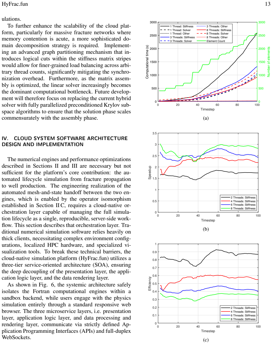
Dynamic Scheduling for Non-Uniform Work- loads: For theO(N 2)SGBEM matrix assembly, the nested loop structure (do jj=1,ii) creates a highly non-uniform, triangular workload. Itera- tions for elements with a high indexiiperform substantially more work than those with a low index. For this loop, theschedule(dynamic) clause is employed. This allows threads t...
-
[11]
In these rou- tines, theschedule(static)clause is used
Static Scheduling for Uniform Workloads: For theO(N)assembly of sparse FEM matrices (e.g., incross_stiff_fluidfor generating coupling blocks (BandB T ) and global force vectors (e.g., informgf_onlyfor generating global load vec- torsR q,R p,R c, andR f ), the computational work per element is relatively constant. In these rou- tines, theschedule(static)cl...
-
[12]
5: Performance analysis of the shared-memory parallelization strategy
Presentation Layer: Responsive Front-End The presentation layer is deployed as an ultra- lightweight Single Page Application (SPA), utilizing HTML5, CSS3, ES6+ JavaScript, and the Tailwind CSS 0 20 40 60 80 100 Timestep 0 500 1000 1500 2000 2500 3000Computational time (s) 0 500 1000 1500 2000 2500 3000 Number of elements 1 Thread: Stiffness 1 Thread: Solv...
work page 2000
-
[13]
Application Logic Layer: Asynchronous Backend Middleware The core orchestration of the platform heavily features a FastAPI-based asynchronous middleware. This acts as the crucial bridge connecting the stateless HTTP proto- col to the legacy Fortran solver core execution. Leverag- ing the Asynchronous Server Gateway Interface (ASGI) and Pydantic object mod...
-
[14]
Process Polling and Zombie Eradication: Utilizing system-level commands (e.g.,ps -o pid,stat), the FastAPI middleware continually probes the active operation tables. If a solver instance is maliciously deadlocked or structurally hanging, it forces aSIGKILLcleanup before deploying the queued computation, freeing the directory sandbox lock and resuming oper...
-
[15]
RegEx I/O Sniffer: Because the primary Fortran binary executes as a closedsubprocess.Popen entity, conventional API progression bars fail. To circumvent this, the middleware initializes an aggressive regular expression File System Snif- fer to scan for generated VTU output strings (simulation_output_t*.vtu) on the storage interface. The maximal numerical ...
-
[16]
Data Processing and Rendering Layer: Cloud-Streamed Visualization Broadcasting gigabyte-scale, highly transient, non- structured 3D grids over standard internet connections immediately exhausts client-side graphic allocation lim- its. To solve this, a remote server-side rendering pipeline utilizing the VTK (Visualization Toolkit) and Trame framework is em...
-
[17]
Cloud-Native Infrastructure and Application Routing To orchestrate global routing streams, handle static as- set caching, and establish an encrypted SSL/TLS perime- ter across these independent microservice nodes, the platform employs an Nginx reverse-proxy ingress con- troller. 1server { 2listen 443 ssl http2 ; 3s e r v e r _ n a m e www . hyfrac . fun ;...
work page 2022
-
[18]
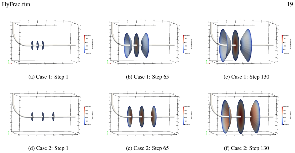
Effect of Cluster Spacing on Stress Shadowing The proximity of simultaneously propagating frac- tures induces a severe mechanical interference known as the stress shadow effect. As a fracture opens, it com- presses the surrounding rock matrix, significantly alter- ing the local stress for adjacent fractures. To quantify this phenomenon, we compare Case 1,...
-
[19]
Influence of Fluid Rheology To investigate the impact of fluid rheology on multi- stage interaction, Case 3 is introduced. This case main- tains the highly constrained 3-meter spacing of Case 1 but replaces the low-viscosity Newtonian fluid with a highly viscous, shear-thinning power-law fluid. The power-law consistency index is set toK=0.2 Pa·s n, and th...
work page 2013
-
[20]
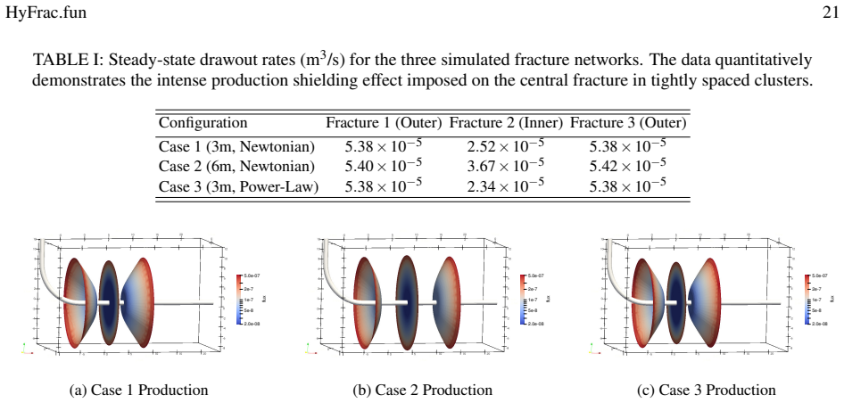
Integrated Production Analysis A distinct advantage of the HyFrac.fun cloud archi- tecture is the automated programmatic handoff of the fi- nal complex 3D fracture meshes directly into the steady- state Darcy production solver. By eliminating the need for manual mesh conversion, the platform allows for rapid lifecycle evaluations. For the production phase...
work page 2005
-
[21]
Operator-based lifecycle integration: A structural analysis of the two governing operator systems reveals that the hydraulic fracture propagation and steady-state production problems are governed by structurally iso- morphic abstract operator families{A,B,C,R}. This isomorphism enables the automated zero-conversion transfer of the evolved 3D fracture mesh...
-
[22]
Detailed adaptive remeshing algorithm: The adap- tive remeshing procedure employed by the propagation engine, which comprises a four-case element splitting and merging decision tree, a characteristic-length-driven mesh quality control scheme, and a localized solution- field projection with singularity regularization for newly created crack-tip nodes, is d...
-
[23]
(2024) 35 are extended to the fully non-planar arbitrarily curved fracture networks considered here
Performance engineering for non-planar multi-stage fractures: The incremental stiffness update strategy, cache-optimized element-renumbering permutation, and hybrid OpenMP parallelization of Mood (2019) 51 and Hu et al. (2024) 35 are extended to the fully non-planar arbitrarily curved fracture networks considered here. A dynamic solver-switching algorithm...
work page 2019
-
[24]
Cloud-native service-oriented architecture: A three- tier architecture, i.e. FastAPI asynchronous back- end, TRAME/VTK server-side rendering service, and lightweight HTML5 front-end, orchestrates the entire lifecycle as a single reproducible server-side workflow, delivering interactive 3D visualization through a stan- dard browser without requiring local ...
work page 2024
-
[25]
pp. SPE–11627. 23B. R. Meyer, “Design formulae for 2-D and 3-D vertical hydraulic fractures: Model comparison and parametric studies,” inSPE Uncon- ventional Resources Conference/Gas Technology Symposium(1986) pp. SPE–15240. 24J. Rungamornrat, M. F. Wheeler, and M. E. Mear, “A numerical tech- nique for simulating nonplanar evolution of hydraulic fractures...
work page 1986
discussion (0)
Sign in with ORCID, Apple, or X to comment. Anyone can read and Pith papers without signing in.