REVIEW 2 major objections 5 minor 49 references
Control of Ferrimagnetic Compensation and Perpendicular Anisotropy in Tb$_x$Co$_{(100-x)}$ with H$^{+}$ ion implantation
T0 review · 2 major / 5 minor · reviewed 2026-08-11 · deepseek-v4-flash
Pith's one-line read Hydrogen implantation into TbCo films shifts the compensation composition and the anisotropy transition by about 6 at.% toward higher Tb content, a change attributed to a reduced Tb sublattice moment.
desk verdict Solid quantitative magneto-ionic study; compensation shift is robust, but the stated 6 at.% anisotropy-transition shift rests on a literature baseline and should be marked approximate. read the letter →
The pith
A machine-rendered reading of the paper's core claim, the machinery that carries it, and where it could break.
The reading
Extended reading notes
Core claim
We find large changes in two important properties: the compensation composition and the Co-rich in-plane to out-of-plane magnetic anisotropy transition composition, both of which move by 6 at.% towards higher Tb concentrations after hydrogen implantation. The paper attributes the compensation shift to a significant reduction of the moment on the Tb sublattice.
Load-bearing premise
The as-deposited value of the in-plane to out-of-plane transition composition xT is assumed to be approximately 10 at.% based on literature (Refs [37,38]) rather than measured in this sample series. The claimed 5-6 at.% shift of xT depends on that baseline; if the true as-deposited xT for these films differs, the quantitative shift changes.
Signed reviews
Editorial analysis
A structured set of objections, weighed in public.
Referee Report
Summary. This manuscript reports a quantitative study of hydrogen ion implantation in amorphous Tb_xCo_(100-x) thin films across x = 10-39 at.%, using two doses (1e17 and 2e17 H+/cm2). The authors combine RBS, NRA, ERDA, XRR, GIXRD, MOKE, and SQUID magnetometry to measure hydrogen retention, film expansion, magnetic anisotropy, hysteresis polarity, coercivity, and saturation magnetization. They find that after implantation the room-temperature compensation composition xc shifts from about 20.5 at.% to roughly 26 at.% Tb, and that Co-rich films with x = 11 and 13 at.% lose perpendicular anisotropy and become in-plane, which they interpret as a shift of the in-plane/out-of-plane transition composition xT from a literature-derived value of about 10 at.% to a higher value. The saturation magnetization data are fitted with a constant-moment model and an environment-dependent moment model; from these fits the authors infer a 23-26% reduction in the Tb sublattice moment and discuss this in terms of an increased sperimagnetic cone angle. The paper concludes that hydrogen loading effectively shifts both xc and xT toward higher Tb concentrations, with no additional shift on doubling the dose.
Significance. If the central measurements hold, this is a useful and well-quantified magneto-ionic study. Its main strengths are the use of ion implantation to control hydrogen loading with precisely measured retained concentrations, the direct determination of xc from coercivity divergence and hysteresis polarity inversion, and the systematic variation of both composition and dose. These features give the compensation-composition shift a much firmer experimental basis than is common in electrochemical studies, where multiple ionic species can move simultaneously. The proposed Tb-moment reduction and the connection to sperimagnetism are physically reasonable but are model-inferred rather than directly measured, and the xT part of the central claim depends on an unmeasured as-deposited baseline. The paper is of clear interest to the rare-earth transition-metal and magneto-ionics communities, and could become acceptable after the baseline and uncertainty issues are addressed.
major comments (2)
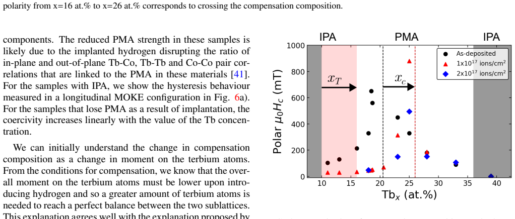
- [Section IV, Fig. 5] The claimed shift of xT by approximately 6 at.% is not directly established. The as-deposited value xT ≈ 10 at.% is taken from Refs. [37,38], and no as-deposited sample with x < 10 at.% is measured in this work; indeed, the authors state that all as-deposited samples, including x = 10 at.%, display square PMA loops, which suggests that the true xT of this sputtered series may lie below 10 at.%. After implantation, x = 11 and 13 at.% are in-plane while x = 16 and 18 at.% are only described as 'tilted', so the post-implantation boundary is not a sharply measured value either. The paper should either measure as-deposited films below 10 at.% or rephrase the claim to state that the upper boundary of the IPA region moves from some value at or below 10 at.% to a value between about 13 and 16 at.%, and the abstract should be modified accordingly.
- [Section IV, Eqs. (2)-(4), Fig. 7] The attribution of the compensation shift to a 23-26% reduction in m_Tb(x=0) is a model inference from the same Ms(x) data rather than an independent determination, and no uncertainties are reported for the fitted parameters. The model fixes m_Co(x=0) = 1.71 μB and the atomic volumes of Ref. [42], treats m_Tb(x=0) and the environment parameter j as free, and then the same data are used both to locate xc and to constrain the Tb moment. The manuscript should provide confidence intervals or a sensitivity analysis showing how the inferred 23-26% reduction changes with the assumed Co moment, atomic volumes, and j value, and should ideally support the Tb-moment reduction with an element-specific technique such as XMCD. As written, the mechanistic conclusion is plausible but is not on the same evidential footing as the measured xc shift.
minor comments (5)
- [Section III, Eq. (1)] Equation (1) appears dimensionally inconsistent as printed: ρCo and ρTb are described as mass densities, but they are multiplied by an areal/atomic density ρ_at, which does not yield g/cm3 unless the formula is intended to use atomic masses. Please check the definitions and units.
- [Section IV, Fig. 5] Because x = 10 at.% as-deposited already shows square PMA loops, the statement that xT is ≈10 at.% in the as-deposited state should be reconciled with this observation, otherwise the baseline for the xT shift is internally ambiguous.
- [Section IV, Fig. 7] The Ms(x) data in Fig. 7 are shown without error bars; adding point-by-point uncertainties would strengthen the comparison between the two models and the dose-dependent fits.
- [Section V] The concluding sentence contains a duplicated phrase: 'the magnetic properties of magnetic properties of amorphous TbxCo(100−x) alloys' should be corrected.
- [Throughout] There are several typographical errors, including 'implantated' in Section IV, 'imlantation' in the Fig. 2 caption, and 'and and' in Section III; these should be corrected in a final proofreading pass.
Circularity Check
No significant circularity: the compensation and anisotropy shifts are directly measured or compared to external literature baselines, and the Tb-moment reduction is presented as an explicitly model-dependent interpretation rather than as an independent prediction.
full rationale
The paper's central results—the shift of the compensation composition xc and the shift of the in-plane/out-of-plane transition xT—are obtained from MOKE hysteresis loops, coercivity divergence, loop polarity reversal, and in-plane/out-of-plane loop shapes, not from the model fits. The xc shift is a direct measurement: the as-deposited xc is identified from a diverging coercivity and polarity change, and the implanted xc is identified in the same way. The xT shift is the difference between the observed post-implantation in-plane behavior at x=11 and 13 at.% and an as-deposited baseline of ≈10 at.% taken from external literature [37,38]; this is a robustness limitation, not circularity, because the baseline is not derived from the same fitted data and the paper does not claim to predict the baseline from its own model. The Tb-moment reduction is obtained by fitting the composition-dependent Ms(x) curves to the environmental model of Suzuki et al., and the paper explicitly acknowledges that this is an interpretation: 'It is however challenging to distinguish a reduction in the measured magnetization due to an increased cone angle from a reduction in the Tb-Co exchange interaction,' and it calls for XMCD and neutron-diffraction experiments. Although Eq. (2) plus the observed xc shift algebraically implies a reduced Tb moment under the fixed-Co-moment assumption, the paper does not present the fitted mTb reduction as an independent verification of the measured xc shift; it presents it as a plausible mechanism with stated assumptions. The only self-citation (Ref. [26], which includes one author of this work) is used to argue that thickness variations above 20 nm are unlikely to alter magnetic properties; that claim is peripheral and not load-bearing for the main results. No uniqueness theorem, ansatz, or fitted quantity is disguised as a prediction. The paper is therefore not circular; the noted xT baseline dependence is an empirical-support concern rather than a circular-reasoning concern.
Assumptions & free parameters
free parameters (4)
- m_Tb(x=0), as-deposited =
not stated in text
- m_Tb(x=0), 1e17 dose =
23% reduction relative to as-deposited
- m_Tb(x=0), 2e17 dose =
26% reduction relative to as-deposited
- j (minimum Co neighbour count) in environment model =
not reported
assumptions (5)
- domain assumption Co atomic moment at x=0 is 1.71 uB and remains unchanged upon hydrogen loading.
- domain assumption As-deposited xT is approximately 10 at.% from literature.
- domain assumption Atomic volumes vCo and vTb from Ref [42] are constant after implantation.
- domain assumption Kerr signal at 670 nm is predominantly sensitive to the Co sublattice.
- domain assumption Both implanted hydrogen doses produce saturated hydrogen concentration.
Cite this review
Pith. "Pith review of Control of Ferrimagnetic Compensation and Perpendicular Anisotropy in Tb$_x$Co$_{(100-x)}$ with H$^{+}$ ion implantation." pith.science (2026). https://pith.science/paper/A3GSGWGU
@misc{pith2026241210132,
  author       = {Pith},
  title        = {Pith review of: Control of Ferrimagnetic Compensation and Perpendicular Anisotropy in Tb$_x$Co$_(100-x)$ with H$^+$ ion implantation},
  year         = {2026},
  howpublished = {\url{https://pith.science/paper/A3GSGWGU}},
  note         = {Machine review of arXiv:2412.10132}
}
abstract
The tuning of magnetic properties through electrochemical loading of hydrogen has recently attracted significant interest as a way to manipulate magnetic devices with electric fields. In this paper we investigate quantitatively the magneto-ionic effect of hydrogen uptake on the magnetic properties of rare-earth transition metal alloy Tb$_x$Co$_{(100-x)}$ in the composition range of $x=10-39$ at.\% using ion implantation. Using this technique we are able to link changes in magnetic behaviour to exact concentrations of hydrogen, isolated from the movement of any other ions that would be a factor in electrochemical studies. The composition of the alloy has been varied alongside the hydrogen dose to characterize the effect of progressive hydrogen loading on the full range of $x$ displaying out-of-plane magnetic anisotropy. We find large changes in two important properties: the compensation composition and the Co-rich in-plane to out-of-plane magnetic anisotropy transition composition, both of which move by 6 at.\% towards higher Tb concentrations after hydrogen implantation. This shift in composition does not increase with a larger dose. From the changes in magnetization we attribute the change in compensation composition to a significant reduction of the moment on the Tb sublattice.
Figures


Figures from the paper (5 more)



Reference graph
Works this paper leans on
-
[42]
D. H. Suzuki, M. Valvidares, P. Gargiani, M. Huang, A. E. Kos- sak, and G. S. Beach, Physical Review B 107, 134430 (2023)
work page 2023
-
[1]
S. Manipatruni, D. E. Nikonov, C.-C. Lin, T. A. Gosavi, H. Liu, B. Prasad, Y .-L. Huang, E. Bonturim, R. Ramesh, and I. A. Young, Nature 565, 35 (2019)
work page 2019
-
[2]
A. Jaiswal, S. Roy, G. Srinivasan, and K. Roy, IEEE Transac- tions on Electron Devices 64, 1818 (2017)
work page 2017
-
[3]
C. Ederer and N. A. Spaldin, Physical Review B—Condensed Matter and Materials Physics 71, 060401 (2005)
work page 2005
-
[4]
J. Heron, D. Schlom, and R. Ramesh, Applied Physics Reviews 1 (2014), https://doi.org/10.1063/1.4870957
-
[5]
K. J. Franke, B. Van de Wiele, Y . Shirahata, S. J. H ¨am¨al¨ainen, T. Taniyama, and S. van Dijken, Physical Review X 5, 011010 (2015)
work page 2015
-
[6]
R. G. Hunt, K. J. Franke, P. M. Shepley, and T. A. Moore, Physical Review B 107, 014409 (2023)
work page 2023
-
[7]
I. Camara, J.-Y . Duquesne, A. Lema ˆıtre, C. Gourdon, and L. Thevenard, Physical Review Applied 11, 014045 (2019)
work page 2019
Show all 49 references
-
[8]
Shuai, M
J. Shuai, M. Ali, L. Lopez-Diaz, J. E. Cunningham, and T. A. Moore, Applied Physics Letters 120 (2022), https://doi.org/10.1063/5.0097172
2022 doi
-
[9]
H. Ohno, a. D. Chiba, a. F. Matsukura, T. Omiya, E. Abe, T. Di- etl, Y . Ohno, and K. Ohtani, Nature 408, 944 (2000)
2000
-
[10]
Navarro-Senent, J
C. Navarro-Senent, J. Fornell, E. Isarain-Chavez, A. Quintana, E. Menendez, M. Foerster, L. Aballe, E. Weschke, J. Nogues, E. Pellicer, et al., ACS applied materials & interfaces10, 44897 (2018)
2018
-
[11]
Bhatnagar-Sch ¨offmann, A
T. Bhatnagar-Sch ¨offmann, A. Kov `acs, R. Pachat, D. Ourdani, A. Lamperti, M.-A. Syskaki, T. da Cˆamara Santa Clara Gomes, Y . Roussign´e, S. Ono, J. Langer, et al., Applied Physics Letters 122 (2023), https://doi.org/10.1063/5.0132870
2023 doi
-
[12]
B. X. Tran, J.-H. Ha, W.-C. Choi, S. Yoon, T.-H. Kim, and J.-I. Hong, Applied Physics Letters 124 (2024), https://doi.org/10.1063/5.0176620
2024 doi
-
[13]
Herrera Diez, Y
L. Herrera Diez, Y . Liu, D. A. Gilbert, M. Belmeguenai, J. V o- gel, S. Pizzini, E. Martinez, A. Lamperti, J. Mohammedi, A. Laborieux, et al. , Physical Review Applied 12, 034005 (2019)
2019
-
[14]
M. U. Hasan, A. E. Kossak, and G. S. Beach, Nature Commu- nications 14, 8510 (2023)
2023
-
[15]
de Rojas, A
J. de Rojas, A. Quintana, G. Rius, C. Stefani, N. Domingo, J. L. Costa-Kr¨amer, E. Men´endez, and J. Sort, Applied Physics Let- ters 120 (2022), https://doi.org/10.1063/5.0079762
2022 doi
-
[16]
de Rojas, A
J. de Rojas, A. Quintana, A. Lopeand ´ıa, J. Salguero, B. Mu˜niz, F. Ibrahim, M. Chshiev, A. Nicolenco, M. O. Liedke, M. But- terling, et al., Nature communications 11, 5871 (2020)
2020
-
[17]
Ameziane, R
M. Ameziane, R. Mansell, V . Havu, P. Rinke, and S. van Di- jken, Advanced Functional Materials 32, 2113118 (2022)
2022
-
[18]
Pravarthana, B
D. Pravarthana, B. Wang, Z. Mustafa, S. Agarwal, K. Pei, H. Yang, and R.-W. Li, Physical Review Applied 12, 054065 (2019)
2019
-
[19]
Zhang, Z.-D
J.-C. Zhang, Z.-D. Liu, C.-H. Zeng, J.-W. Luo, Y .-D. Deng, X.- Y . Cui, and Y .-N. Chen, Rare Metals41, 3946 (2022)
2022
-
[20]
Takemura, T
R. Takemura, T. Kawahara, K. Miura, H. Yamamoto, J. Hayakawa, N. Matsuzaki, K. Ono, M. Yamanouchi, K. Ito, H. Takahashi, et al. , IEEE Journal of Solid-State Circuits 45, 869 (2010)
2010
-
[21]
Huang, M
M. Huang, M. U. Hasan, K. Klyukin, D. Zhang, D. Lyu, P. Gar- giani, M. Valvidares, S. She ffels, A. Churikova, F. B ¨uttner, et al., Nature Nanotechnology 16, 981 (2021)
2021
-
[22]
A. J. Tan, M. Huang, C. O. Avci, F. B ¨uttner, M. Mann, W. Hu, C. Mazzoli, S. Wilkins, H. L. Tuller, and G. S. Beach, Nature Materials 18, 35 (2019). 9
2019
-
[23]
A. E. Kossak, M. Huang, P. Reddy, D. Wolf, and G. S. Beach, Science Advances 9, eadd0548 (2023)
2023
- [24]
-
[25]
She ffels, P
S. She ffels, P. P. Balakrishnan, M. Huang, S. Muramoto, J. Borchers, J. Dura, A. Grutter, and G. Beach, Applied Physics Letters 122 (2023), https://doi.org/10.1063/5.0128835
2023 doi
-
[26]
Ciuciulkaite, K
A. Ciuciulkaite, K. Mishra, M. V . Moro, I.-A. Chioar, R. M. Rowan-Robinson, S. Parchenko, A. Kleibert, B. Lindgren, G. Andersson, C. S. Davies, et al., Physical Review Materials 4, 104418 (2020)
2020
-
[27]
Bj ¨orck and G
M. Bj ¨orck and G. Andersson, Journal of Applied Crystallogra- phy 40, 1174 (2007)
2007
-
[28]
Mayer, in AIP conference proceedings, V ol
M. Mayer, in AIP conference proceedings, V ol. 475 (American Institute of Physics, 1999) pp. 541–544
1999
-
[29]
Str ¨om and D
P. Str ¨om and D. Primetzhofer, Journal of instrumentation 17, P04011 (2022)
2022
-
[30]
J. F. Ziegler, M. D. Ziegler, and J. P. Biersack, Nuclear In- struments and Methods in Physics Research Section B: Beam Interactions with Materials and Atoms 268, 1818 (2010)
2010
-
[31]
Krupinski, J
M. Krupinski, J. Hintermayr, P. Sobieszczyk, and M. Albrecht, Physical Review Materials 5, 024405 (2021)
2021
-
[32]
Bylin, P
J. Bylin, P. Malinovskis, A. Devishvili, R. H. Scheicher, and G. K. P´alsson, Physical Review B 106, 104110 (2022)
2022
-
[33]
J. M. Swenson and S. A. Norris, Journal of Physics: Condensed Matter 30, 304003 (2018)
2018
-
[34]
Komander, M
K. Komander, M. V . Moro, S. A. Droulias, J. M ¨uggenburg, G. K. P´alsson, T. Nyberg, D. Primetzhofer, and M. Wol ff, Nu- clear Instruments and Methods in Physics Research Section B: Beam Interactions with Materials and Atoms 455, 57 (2019)
2019
-
[35]
Pitthan, P
E. Pitthan, P. Petersson, T. T. Tran, D. Moldarev, R. Kaur, J. Shams-Latifi, P. Str¨om, M. Hans, M. Rubel, and D. Primet- zhofer, Nuclear Materials and Energy 34, 101375 (2023)
2023
-
[36]
Khorsand, M
A. Khorsand, M. Savoini, A. Kirilyuk, A. Kimel, A. Tsukamoto, A. Itoh, and T. Rasing, Physical review letters 110, 107205 (2013)
2013
-
[37]
Odagiri, H
M. Odagiri, H. Imaeda, A. Yagmur, Y . Kurokawa, S. Sumi, H. Awano, and K. Tanabe, Applied Physics Letters124 (2024), https://doi.org/10.1063/5.0196720
2024 doi
-
[38]
Th ´orarinsd´ottir, B
K. Th ´orarinsd´ottir, B. Thorbjarnard ´ottir, U. Arnalds, and F. Magnus, Journal of Physics: Condensed Matter 35, 205802 (2023)
2023
-
[39]
Yagmur, S
A. Yagmur, S. Sumi, H. Awano, and K. Tanabe, Physical Re- view B 103, 214408 (2021)
2021
-
[40]
Alebrand, M
S. Alebrand, M. Gottwald, M. Hehn, D. Steil, M. Cinchetti, D. Lacour, E. E. Fullerton, M. Aeschlimann, and S. Mangin, Applied Physics Letters 101 (2012), https://doi.org/10.1063/1.4759109
2012 doi
-
[41]
Harris, K
V . Harris, K. Aylesworth, B. Das, W. Elam, and N. Koon, Phys- ical review letters 69, 1939 (1992)
1992
-
[43]
Jaccarino and L
V . Jaccarino and L. Walker, Physical Review Letters 15, 258 (1965)
1965
-
[44]
J. J. Rhyne, in Alloys and Intermetallics , Handbook on the Physics and Chemistry of Rare Earths, V ol. 2 (Elsevier, 1979) pp. 259–294
1979
-
[45]
Uchiyama, Materials chemistry and physics 42, 38 (1995)
S. Uchiyama, Materials chemistry and physics 42, 38 (1995)
1995
-
[46]
Vas’ kovskiy, O
V . Vas’ kovskiy, O. Adanakova, K. Balymov, N. Kulesh, A. Svalov, and E. Stepanova, Physics of the Solid State 57, 1142 (2015)
2015
-
[47]
Makarochkin, E
I. Makarochkin, E. Kudyukov, E. Stepanova, G. Kurlyand- skaya, V . Vas’ Kovskiy, and A. Svalov, inAIP Conference Pro- ceedings, V ol. 2313 (AIP Publishing, 2020)
2020
-
[48]
Givord, A
D. Givord, A. Li ´enard, J. Rebouillat, and J. Schweizer, Physica B+ C 130, 351 (1985)
1985
-
[49]
J. M. D. Coey, J. Chappert, J. Rebouillat, and T. Wang, Physical Review Letters 36, 1061 (1976)
1976
Reviewed August 11, 2026 · model on record in the stance chip above.
Discussion (0). Continue with ORCID to comment.