REVIEW 2 major objections 4 minor 45 references
The aerodynamic performance of a transonic airfoil with spanwise forcing
T0 review · 2 major / 4 minor · reviewed 2026-08-08 · deepseek-v4-flash
Pith's one-line read Spanwise wall waves push a transonic airfoil's shock downstream and raise efficiency by up to 11%.
desk verdict Solid DNS parametric study of spanwise travelling waves on a transonic airfoil, but the headline practical gains rest on a low-Reynolds, tripped condition that the authors themselves flag; deserves peer review with pushback on framing. read the letter →
The pith
A machine-rendered reading of the paper's core claim, the machinery that carries it, and where it could break.
The reading
What carries the argument
The central object is the streamwise-travelling wave of spanwise wall velocity, $W_w(x,t)=A\sin(\kappa_x x-\omega t)$, applied to a portion of the suction side of the V2C transonic airfoil. The mechanism that carries the argument is a two-time-scale interaction: the wall waves rapidly suppress near-wall turbulence and skin friction, and the resulting loss of near-wall momentum slowly allows the shock to move downstream, changing the global pressure field. A modified Ducros sensor, $\Theta$, locates the shock, and the shock position $x_s$ and intensity $I$ track the control effect.
What would settle it
Run the same V2C airfoil at the same Mach number and control parameters but with $Re_\infty=10^6$ or higher (or in a cryogenic wind tunnel with natural transition), and inspect whether the suction-side shock still moves downstream and the separation bubble still lengthens in proportion to friction reduction. If the shock position and the bubble length do not respond to StTW at flight Reynolds numbers, the central mechanism is a low-Reynolds artifact rather than a general compressible-flow effect.
Extended reading notes
Core claim
The central claim is that spanwise forcing via streamwise-travelling waves acts on the shock wave itself: with properly chosen wavelength, frequency, amplitude, and actuation extent, the shock on the suction side is delayed toward the trailing edge, the supersonic low-pressure region widens, and the airfoil's aerodynamic efficiency rises. The paper shows that the initial, fast effect of the control is a local reduction of skin friction; on a slower time scale of about eight convective units, the reduced friction perturbs the shock/boundary-layer equilibrium, displacing the shock downstream. The displaced shock is stronger, the boundary layer undergoes a stronger adverse pressure gradient and separates, and the length of the resulting recirculation bubble correlates with the amount of friction reduction. Changes in friction and pressure drag are comparable in magnitude, which is why total drag changes little while lift changes a lot.
Load-bearing premise
The results rest on a Reynolds number of 300,000 with forced transition, which is far below flight conditions; the paper itself states that at least $Re_\infty=10^6$ is needed to put the observations on firmer physical ground, so if the shock-delaying effect does not persist at flight Reynolds numbers, the practical claim loses its footing.
Editorial extensions
If this is right
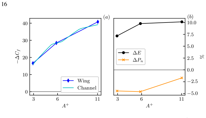
- StTW reduce skin friction except when the control parameters sit in the channel-flow drag-increasing region, and the parametric trends match incompressible channel flow at $Re_\tau=200$.
- Because the delayed shock is stronger, pressure drag increases by roughly the same amount that friction drag decreases, so total drag changes by about 1% while lift changes substantially.
- Re-trimming the airfoil to recover the original lift turns the lift gain into an efficiency gain of up to 11% and, extrapolated to a full aircraft, a net power saving near 12%.
- An actuator for the travelling waves needs an efficiency of only about 0.045 to produce a net power gain at the aircraft level.
- The length of the separated region under the shock grows with friction reduction, and a sufficiently large bubble can generate a secondary, weaker shock.
Reading between the lines
- If the shock-delaying mechanism is generic, then any drag-reducing surface treatment, including passive riblets, may alter shock position and pressure drag on transonic wings, not just friction.
- The two-time-scale behavior suggests a control strategy: local skin-friction sensors could act as early indicators of the slower shock relocation, and actuation could be modulated during unsteady or buffet conditions to manage the ~8-convective-unit lag.
- The paper's aircraft-level estimate assumes the control effect is independent of spanwise station and Reynolds number; a three-dimensional wing simulation or wind-tunnel test would show whether the shock-delay mechanism survives finite-wing corrections and would refine the 12% figure.
Editorial analysis
A structured set of objections, weighed in public.
Referee Report
Summary. The manuscript presents direct numerical simulations of a transonic supercritical V2C airfoil at M∞=0.7 and Re∞=3e5, with spanwise-traveling-wave (StTW) forcing applied to part of the suction side. Twenty-nine DNS cases explore the control-parameter space (amplitude, wavenumber, frequency, and start/end of actuation). The central finding is that StTW that reduce local skin friction also, for favorable parameter combinations, move the suction-side shock downstream, increase lift and aerodynamic efficiency, while the total drag changes only slightly; a separation bubble appears whose length correlates with the friction-reduction level. The paper also reports a transient analysis linking the immediate friction reduction to the slower shock displacement, compares local friction-reduction trends with incompressible channel data, and uses a RANS-based polar to estimate net power savings at aircraft level, concluding with a potential 12% net saving.
Significance. The paper's core DNS result is significant and appears numerically well supported. The validation against Quadrio et al. (2022), the spanwise-domain check, the quantified statistical errors, and the systematic 29-case parameter study are strengths. The claim that StTW can modify pressure drag through shock manipulation rather than acting on skin friction alone is an important conceptual advance, and the parameter-space similarity with channel flow, together with the transient mechanism, gives the work broader value. The main significance is limited by the single low-Reynolds-number condition and by the reliance on unvalidated extrapolations for the aircraft-level savings; nevertheless, if appropriately qualified, the DNS results provide a useful and publishable contribution.
major comments (2)
- [Section 5 and Section 4.1] The entire study is conducted at a single Reynolds number, Re∞=3e5, with forced tripping, and the central shock-displacement mechanism is tied to boundary-layer thickening and separation. Section 5 explicitly acknowledges that a flight Reynolds number of at least 1e6 is required to give the observations firmer physical ground, and Section 4.1 states that the flow reversal is likely connected with the limited Reynolds number. Because the abstract and Section 5 present the efficiency gain as the headline result, the authors should either provide a higher-Reynolds-number data point (DNS or a carefully justified RANS/DNS comparison) or explicitly and consistently reframe the shock-delay/efficiency claim as a low-Reynolds demonstration whose flight relevance is not yet established. The current text wavers between a strong claim ('enhancing aerodynamic efficiency') and a caveat that appears only in the final discussion.
- [Section 3.3, Eq. (3.5) and assumptions (i)-(v)] The net power saving and the aircraft-level 12% estimate depend on a RANS polar obtained with SU2 that is not validated against the present DNS or any experimental data, and on five explicit assumptions including spanwise uniformity, no Reynolds/Mach dependence, non-lift-induced drag equal to one-third of total drag, and actuated area equal to one-quarter of the wing surface. These choices are not sensitivity-tested. The quantitative statements about a 12% net gain and the required actuator efficiency of 0.045 therefore go beyond what the DNS directly support. Please either validate the RANS polar against the DNS incidences already available (REF/RREF and C10/R10) and provide a sensitivity study for assumptions (i)-(v), or clearly label the aircraft extrapolation as a rough illustrative estimate.
minor comments (4)
- [Section 3.3] The text states 'We find a minimum value of ΔPn for the case C27, corresponding to A+ = 6', but the table lists the A+≈6 case as C26 and no case C27 exists; this appears to be a typo.
- [Section 4.1] The sentence 'The compressible boundary layer thicknesses δ*, θ and shape factor H are are shown' contains a duplicated 'are'.
- [Section 4.1] There are several misspellings that should be corrected: 'dowstream' for 'downstream', 'minumum' for 'minimum', and 'law-ot-the-wall' for 'law-of-the-wall'.
- [Section 3.2] The claim of 'remarkable agreement' with the incompressible channel data in Figure 8 should be tempered by the fact that the quantitative value of ΔCf depends on the arbitrary choice of the extraction location x/c=0.4, as documented in Appendix A.
Circularity Check
No significant circularity: the central shock-displacement and efficiency claims are new DNS outputs, not reductions of fitted inputs or self-citation chains.
full rationale
The paper's central claims — that spanwise traveling-wave forcing shifts the suction-side shock downstream, increases lift and aerodynamic efficiency, and produces a separation bubble whose length correlates with friction reduction — are direct outputs of 29 DNS simulations. These results are not fitted to, nor derived from, the incompressible channel-flow database of Gatti & Quadrio (2016); that database is used only to define parameter-space paths (L1, L2, L3) and for a qualitative comparison of local friction trends, with the paper explicitly warning that a quantitative comparison is impossible owing to curvature, pressure gradients, and spatial transients. The baseline solver and setup are validated against Quadrio et al. (2022), but this is an independent reproduction of the reference case, not an input that forces the new conclusions. The net-power and aircraft-extrapolation estimates use a separate RANS polar computed with SU2 and clearly stated assumptions about lift sharing, spanwise uniformity, and actuator efficiency; no equation in the paper reduces to its own inputs. The acknowledged low-Reynolds-number limitation is an external-validity concern, explicitly disclosed in Section 5, not a circularity. No self-definition, fitted-input-renamed-as-prediction, or load-bearing self-citation chain can be exhibited from the text.
Assumptions & free parameters
free parameters (3)
- Friction evaluation location x/c=0.4 =
0.4
- Tripping force intensity =
100 U_inf^2/c
- Exponential smoothing length scale =
0.05 chord
assumptions (5)
- standard math The compressible Navier-Stokes equations with ideal gas, Fourier's law and Newtonian stress are the correct governing equations
- domain assumption The computational grid (4096x512x256, Delta x+ < 10, Delta y+ < 0.5, Delta z+ < 5) provides a fully resolved DNS
- domain assumption Forced transition via a Gaussian volume force at 0.1c yields a representative turbulent boundary layer
- ad hoc to paper The uncontrolled wing polar needed for the net power balance can be obtained from RANS (SU2) rather than DNS
- ad hoc to paper Aircraft-level extrapolation assumptions (i)-(v): spanwise uniformity, no Re/M dependence, non-lift-induced drag equals one-third of total, control does not change polar slopes, actuated area is one-fourth of wing surface
Cite this review
Pith. "Pith review of The aerodynamic performance of a transonic airfoil with spanwise forcing." pith.science (2026). https://pith.science/paper/NEXD4IUJ
@misc{pith2026250204516,
  author       = {Pith},
  title        = {Pith review of: The aerodynamic performance of a transonic airfoil with spanwise forcing},
  year         = {2026},
  howpublished = {\url{https://pith.science/paper/NEXD4IUJ}},
  note         = {Machine review of arXiv:2502.04516}
}
read the original abstract
Spanwise wall forcing in the form of streamwise-travelling waves is applied to the suction side of a transonic airfoil with a shock wave to reduce aerodynamic drag. The study, conducted using direct numerical simulations, extends earlier findings by Quadrio et al. (J. Fluid Mech. vol. 942, 2022, R2) and confirms that the wall manipulation shifts the shock wave on the suction side towards the trailing edge of the profile, thereby enhancing its aerodynamic efficiency. A parametric study over the parameters of wall forcing is carried out for the Mach number set at 0.7 and the Reynolds number at 300,000. Similarities and differences with the incompressible plane case are discussed; for the first time, we describe how the interaction between the shock wave and the boundary layer is influenced by flow control via spanwise forcing. With suitable combinations of control parameters, the shock is delayed, and results in a separated region whose length correlates well with friction reduction. The analysis of the transient process following the sudden application of control is used to link flow separation with the intensification of the shock wave.
Figures


Figures from the paper (17 more)




Reference graph
Works this paper leans on
-
[1]
, " * write output.state after.block = add.period write newline
ENTRY address author booktitle chapter edition editor howpublished institution journal key month note number organization pages publisher school series title type volume year eprint label extra.label sort.label short.list INTEGERS output.state before.all mid.sentence after.sentence after.block FUNCTION init.state.consts #0 'before.all := #1 'mid.sentence ...
-
[2]
write newline
" write newline "" before.all 'output.state := FUNCTION n.dashify 't := "" t empty not t #1 #1 substring "-" = t #1 #2 substring "--" = not "--" * t #2 global.max substring 't := t #1 #1 substring "-" = "-" * t #2 global.max substring 't := while if t #1 #1 substring * t #2 global.max substring 't := if while FUNCTION word.in bbl.in capitalize " " * FUNCT...
-
[3]
Abbas, A. , de Vicente , J. & Valero, E. 2013 Aerodynamic technologies to improve aircraft performance . Aerosp. Sc & Tech. 28 (1), 100--132
work page 2013
-
[4]
Auteri, F. , Baron, A. , Belan, M. , Campanardi, G. & Quadrio, M. 2010 Experimental assessment of drag reduction by traveling waves in a turbulent pipe flow . Phys. Fluids 22 (11), 115103/14
work page 2010
-
[5]
Banchetti, J. , Luchini, P. & Quadrio, M. 2020 Turbulent drag reduction over curved walls . J. Fluid Mech. 896 , 1--23
work page 2020
-
[6]
Bird, J. , Santer, M. & Morrison, J.F. 2018 Experimental Control of Turbulent Boundary Layers with In-plane Travelling Waves . Flow Turbul. Combust. 100 (4), 1015--1035
work page 2018
-
[7]
D \'e lery, J. & Marvin, J. G. 1986 Shock-Wave Boundary Layer Interactions\/ . AGARDograph \/ 280. AGARD
work page 1986
-
[8]
Doerffer, P. , Flaszynski, P. , Dussauge, J.-P. , Babinsky, H. , Grothe, P. , Petersen, A. & Billard, F. , ed. 2021 Transition Location Effect on Shock Wave Boundary Layer Interaction : Experimental and Numerical Findings from the TFAST Project \/ , Notes on Numerical Fluid Mechanics and Multidisciplinary Design , vol. 144 . Cham: Springer International P...
work page 2021
Show all 45 references
-
[9]
, Ferrand, V
Ducros, F. , Ferrand, V. , Nicoud, F. , Weber, C. , Darracq, D. , Gacherieu, C. & Poinsot, T. 1999 Large- Eddy Simulation of the Shock / Turbulence Interaction . J. Comp. Phys. 152 (2), 517--549
1999
-
[10]
, Zheltovodov, A
Fang, J. , Zheltovodov, A. , Yao, Y. , Moulinec, C. & Emerson, D. 2020 On the turbulence amplification in shock-wave/turbulent boundary layer interaction . J. Fluid Mech. 897 , A32
2020
-
[11]
, Hasegawa, Y
Frohnapfel, B. , Hasegawa, Y. & Quadrio, M. 2012 Money versus time: Evaluation of flow control in terms of energy consumption and convenience . J. Fluid Mech. 700 , 406--418
2012
-
[12]
, Santer, M
Fumarola, I. , Santer, M. & Morrison, J. 2024 Simultaneous Measurements of Surface Spanwise Waves and Velocity in a Turbulent Boundary Layer . Flow Turb. Comb. 113 (1), 139--158
2024
-
[13]
& Quadrio, M
Gallorini, E. & Quadrio, M. 2024 Spatial discretization effects in spanwise forcing for turbulent drag reduction . J. Fluid Mech. 982 , A11
2024
-
[14]
, Zanolini, M
Gattere, F. , Zanolini, M. , Gatti, D. , Bernardini, M. & Quadrio, M. 2024 Turbulent drag reduction with streamwise-travelling waves in the compressible regime . J. Fluid Mech. 987 , A30
2024
-
[15]
, G \"u ttler, A
Gatti, D. , G \"u ttler, A. , Frohnapfel, B. & Tropea, C. 2015 Experimental assessment of spanwise-oscillating dielectric electroactive surfaces for turbulent drag reduction in an air channel flow . Exp. Fluids 56 (5), 1--15
2015
-
[16]
& Quadrio, M
Gatti, D. & Quadrio, M. 2016 Reynolds-number dependence of turbulent skin-friction drag reduction induced by spanwise forcing . J. Fluid Mech. 802 , 553--58
2016
-
[17]
, Zhang, K
Graver, B. , Zhang, K. & Rutherford, D. 2019 CO2 emissions from commercial aviation, 2018 . Tech. Rep.\/ . International Council on Clean Transportion
2019
-
[18]
, Schmidt, W
Jameson, A. , Schmidt, W. & Turkel, E. 1981 Numerical solution of the Euler equations by finite volume methods using Runge Kutta time stepping schemes. In 14th Fluid and Plasma Dynamics Conference \/ . Palo Alto,CA,U.S.A.: American Institute of Aeronautics and Astronautics
1981
-
[19]
, Mangiavacchi, N
Jung, W.J. , Mangiavacchi, N. & Akhavan, R. 1992 Suppression of turbulence in wall-bounded flows by high-frequency spanwise oscillations . Phys. Fluids A 4 (8) , 1605--1607
1992
-
[20]
, Hasegawa, Y
Kasagi, N. , Hasegawa, Y. & Fukagata, K. 2009 Towards cost-effective control of wall turbulence for skin-friction drag reduction. In Advances in Turbulence XII \/ (ed. B. Eckhardt ) , , vol. 132 , pp. 189--200 . Springer
2009
-
[21]
, Hartog, F.H
Knoop, M.W. , Hartog, F.H. , Schrijer, F.F.J. , van Campenhout , O.W.G. , van Nesselrooij , M. & van Oudheusden , B.W. 2024 Experimental assessment of square-wave spatial spanwise forcing of a turbulent boundary layer . Exp Fluids 65 (5), 65
2024
-
[22]
, Klausmeyer, S.M
Laflin, K.R. , Klausmeyer, S.M. , Zickuhr, T. , Vassberg, J.C. , Wahls, R.A. , Morrison, J.H. , Brodersen, O.P. , Rakowitz, M.E. , Tinoco, E.N. & Godard, J.-L. 2005 Data Summary from Second AIAA Computational Fluid Dynamics Drag Prediction Workshop . J. Aircraft 42 (5), 1165--1178
2005
-
[23]
, Osher, S
Liu, X.D. , Osher, S. & Chan, T. 1994 Weighted Essentially Non-Oscillatory Schemes . J. Comp. Phys. 115
1994
-
[24]
, Chandran, D
Marusic, I. , Chandran, D. , Rouhi, A. , Fu, M.K. , Wine, D. , Holloway, B. , Chung, D. & Smits, A.J. 2021 An energy-efficient pathway to turbulent drag reduction . Nat. Commun. 12 (1), 5805
2021
-
[25]
, Tognaccini, R
Mele, B. , Tognaccini, R. & Catalano, P. 2016 Performance assessment of a transonic wing-body configuration with riblets installed . J. Aircr. 53 (1), 129--140
2016
-
[26]
, Bernardini, M
Memmolo, A. , Bernardini, M. & Pirozzoli, S. 2018 Scrutiny of buffet mechanisms in transonic flow . Int. J. Numer. Meth. Fluids 28 (5), 1031--1046
2018
-
[27]
2011 Numerical Methods for High-Speed Flows
Pirozzoli, S. 2011 Numerical Methods for High-Speed Flows . Annu. Rev. Fluid Mech. 43 (1), 163--194
2011
-
[28]
, Bernardini, M
Pirozzoli, S. , Bernardini, M. & Grasso, F. 2010 Direct numerical simulation of transonic shock/boundary layer interaction under conditions of incipient separation . J. Fluid Mech. 657 , 361--393
2010
-
[29]
& Ruchala, P
Placek, R. & Ruchala, P. 2018 The flow separation development analysis in subsonic and transonic flow regime of the laminar airfoil . Transp. Res. Proc. 29 , 323--329
2018
-
[30]
, Chiarini, A
Quadrio, M. , Chiarini, A. , Banchetti, J. , Gatti, D. , Memmolo, A. & Pirozzoli, S. 2022 Drag reduction on a transonic airfoil . J. Fluid. Mech. 942 , R2, 1--10
2022
-
[31]
& Ricco, P
Quadrio, M. & Ricco, P. 2004 Critical assessment of turbulent drag reduction through spanwise wall oscillation . J. Fluid Mech. 521 , 251--271
2004
-
[32]
& Ricco, P
Quadrio, M. & Ricco, P. 2011 The laminar generalized Stokes layer and turbulent drag reduction . J. Fluid Mech. 667 , 135--157
2011
-
[33]
, Ricco, P
Quadrio, M. , Ricco, P. & Viotti, C. 2009 Streamwise-traveling waves of spanwise wall velocity for turbulent drag reduction . J. Fluid Mech. 627 , 161--178
2009
-
[34]
& Luchini, P
Russo, S. & Luchini, P. 2017 A fast algorithm for the estimation of statistical error in DNS (or experimental) time averages . J. Comput. Phys. 347 , 328--340
2017
-
[35]
& \"O rl \"u , R
Schlatter, P. & \"O rl \"u , R. 2012 Turbulent boundary layers at moderate Reynolds numbers: Inflow length and tripping effects . J. Fluid Mech. 710 , 5--34
2012
-
[36]
2012 Temporal and spatial transients in turbulent boundary layer flow over an oscillating wall
Skote, M. 2012 Temporal and spatial transients in turbulent boundary layer flow over an oscillating wall . Int. J. Heat Fluid Flow 38 , 1--12
2012
-
[37]
Smits, A. J. & Dussauge, J.P. 2006 Turbulent Shear Layers in Supersonic Flow \/ . Springer
2006
-
[38]
& Allmaras, S
Spalart, P. & Allmaras, S. 1992 A one-equation turbulence model for aerodynamic flows. In 30th Aerospace Sciences Meeting and Exhibit \/ . American Institute of Aeronautics and Astronautics
1992
-
[39]
, Asproulias, I
Szubert, D. , Asproulias, I. , Grossi, F. , Duvigneau, R. , Hoarau, Y. & Braza, M. 2016 Numerical study of the turbulent transonic interaction and transition location effect involving optimisation around a supercritical aerofoil . Eur. J. Mech. B / Fluids 55 , 380--393
2016
-
[40]
& Larsson, J
Trettel, A. & Larsson, J. 2016 Mean velocity scaling for compressible wall turbulence with heat transfer . Physics of Fluids 28 (2), 026102
2016
-
[41]
1995 Convergence to Steady State Solutions of the Euler Equations on Unstructured Grids with Limiters
Venkatakrishnan, V. 1995 Convergence to Steady State Solutions of the Euler Equations on Unstructured Grids with Limiters . J. Comp. Phys. 118 (1), 120--130
1995
-
[42]
, Ricco, P
Xu, D. , Ricco, P. & Duan, L. 2023 Decomposition of the skin-friction coefficient of compressible boundary layers . Phys. Fluids 35 (3), 035107
2023
-
[43]
& Hussain, F
Yao, J. & Hussain, F. 2019 Supersonic turbulent boundary layer drag control using spanwise wall oscillation . J . Fluid Mech. 880 , 388--429
2019
-
[44]
& Skote, M
Yudhistira, I. & Skote, M. 2011 Direct numerical simulation of a turbulent boundary layer over an oscillating wall . J. Turbulence 12 (9), 1--17
2011
-
[45]
, De Tullio, N
Zauner, M. , De Tullio, N. & Sandham, N. D. 2019 Direct Numerical Simulations of Transonic Flow Around an Airfoil at Moderate Reynolds Numbers . AIAA J. 57 (2), 597--607
2019
Reviewed August 8, 2026 · model on record in the stance chip above.
Discussion (0). Continue with ORCID to comment.