REVIEW 2 major objections 5 minor 15 references
Repurposing acquisition devices into trigger-based timing synchronization of breakdown events during MITICA high voltage holding experiments
T0 review · 2 major / 5 minor · reviewed 2026-07-10 · grok-4.5
Pith's one-line read Repurposed RedPitaya boards can reconstruct breakdown timing to 8 ns by recording trigger bit-fields and back-projecting static fiber and logic delays.
desk verdict Solid engineering methods paper: asynchronous THub timing from commodity RedPitayas works and delivers usable BD lags; residual physics interpretation is incomplete but does not sink the method. read the letter →
The pith
A machine-rendered reading of the paper's core claim, the machinery that carries it, and where it could break.
The reading
What carries the argument
The Timing Hub (THub): a RedPitaya whose ADC bus is rerouted to sample six LVDS trigger inputs as a bit-field transient; rising-edge sample counts yield raw arrival times that are corrected by the back-projection of Eq. (1) using once-measured fiber and logic offsets.
What would settle it
Repeat the round-trip and external-trigger delay measurements of Fig. 8 at several points during a long campaign; any drift larger than a few samples would leave residual offsets that destroy the reported 600 ns and 1.3 µs correlations.
Extended reading notes
Core claim
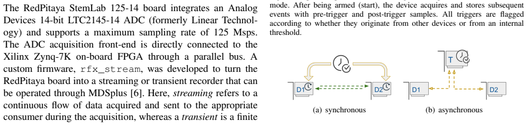
An asynchronous architecture that records the logical envelope of all trigger lines on a single RedPitaya and then subtracts the calibrated static delays of fiber and internal logic reconstructs true relative event times across a sparse, tree-connected set of electrically isolated digitizers to the 8 ns resolution of the 125 Msps clock, without requiring a distributed phase-locked time base.
Load-bearing premise
The total delay of every optical fiber and every device's internal trigger logic stays fixed for the whole multi-month campaign and can therefore be captured by a single static calibration.
Editorial extensions
If this is right
- Any plant that already has optical trigger fibers can add relative timing at 8 ns resolution by inserting a few THubs and performing a one-time delay calibration.
- Observed inter-probe lags become a diagnostic for discriminating in-vessel versus out-of-vessel breakdowns once the core-snubber contribution is fully modeled.
- Tree topologies of THubs can be reconfigured after the shot; the reconstruction algorithm simply accumulates the parent-to-child delay path.
- The same firmware pattern works for any transient recorder that can emit a trigger-out and sample multiple digital lines at its native rate.
Reading between the lines
- The 1.3 µs GP00-to-Rogowski lag, if confirmed as core-snubber delay, supplies an independent estimate of the effective permeability of the FINEMET cores under real BD currents.
- Because absolute time is supplied only by NTP on the root hub, the method can be upgraded to GPS or White-Rabbit absolute stamps without changing the relative-delay layer.
- The unsupervised CAE-plus-GMM classifier used to reject false triggers is itself a reusable pre-filter for any sparse, high-rate BD archive.
Signed reviews
Editorial analysis
A structured set of objections, weighed in public.
Referee Report
Summary. The manuscript presents an asynchronous relative-timing architecture for synchronizing sparse, electrically insulated digitizers during MITICA high-voltage holding tests. RedPitaya boards are repurposed as Timing Hubs (THubs) that both multiplex optical triggers and record the multi-channel trigger bit-field as a 125 Msps transient. Offline back-projection of measured static delays (fiber TOF, electro-optic conversion, device logic Δ_tr/Δ_th, and THub processing t_p) via Eqs. (1)–(3) reconstructs event times across a tree of hubs and probes. The method is applied to three 2024–2025 campaigns; after unsupervised CAE+GMM cleaning of false triggers, cross-correlation of Class-A waveforms yields reproducible inter-probe lags (~600 ns HVD–TL1, few-ns GP00 internal, ~1.3 µs GP00–Rogowski). Absolute time is anchored by NTP on the root hub.
Significance. If the static-delay reconstruction holds, the work supplies a practical, low-cost alternative to PTP/White-Rabbit for transient localization in harsh HV environments where commercial synchronized digitizers are unavailable or electrically unsuitable. The approach re-uses an existing optical trigger fabric, is self-calibratable in principle, and is demonstrated on a full-scale ITER-relevant facility. Explicit strengths include the open delay equations, the multi-THub tree correction, the documented firmware features required for the method, and the honest discussion of residual physics discrepancies. These make the paper useful both for the fusion-diagnostics community and for other sparse, high-isolation acquisition networks.
major comments (2)
- [Sec. II-D, Eq. (1)–(3)] Sec. II-D and Eq. (1): The reconstruction t_true,i = t_s,i - (t_dl,i + t_p) is load-bearing and rests on the claim that every component of t_dl,i (fiber TOF, electro-optic stages, FPGA logic, and especially the threshold term Δ_th of Eq. (3)) remains constant to a few samples over the multi-month campaign. The paper reports a single manual calibration (450 ns / 140 ns fibers, Δ_tr = 100 ns, t_p = 80 ns) and never re-measures or bounds drift. A short stability check (repeat round-trip measurements at campaign start/mid/end, or a bound on temperature/voltage dependence of Δ_th) is needed to underwrite the 8 ns claim; without it the offline back-projection remains an unquantified engineering risk.
- [Sec. III-B, Figs. 12–14] Sec. III-B / Fig. 12–14: After filtering, only 156 Class-A pulses remain, ME10 data are excluded, and the GP00–Rogowski lag (~1.3 µs) substantially exceeds pure TL propagation (~270 ns). The core-snubber hypothesis is plausible but untested against a circuit model or additional probes. The central claim that the architecture enables BD localization therefore rests on a small, partially incomplete dataset whose largest lag is still under investigation. Either enlarge the validated set or qualify the localization claim more carefully (e.g., “inter-probe lag measurement” rather than full localization).
minor comments (5)
- [Sec. II-B, Fig. 4] Fig. 4 caption and surrounding text: the rerouting of the ADC bus to LVDS/TMDS33 ports is clear in principle, but a one-line statement of the resulting bit-to-port mapping (or a small table) would help readers reproduce the firmware change.
- [Sec. II-D, Eq. (3)] Eq. (3): Δ_d = 85 ns is stated for the RedPitaya; indicate whether this value was measured on the same boards used in the campaign or taken from a generic characterization.
- [Sec. III-A] Sec. III-A: the CAE loss weights (α=5, β=5, W=64) and the choice of four GMM classes are free hyper-parameters. A brief sensitivity note (or a statement that the Class-A selection is robust under modest changes) would strengthen confidence that the delay histograms are not classification artifacts.
- [Front matter / Refs.] Typographical: “Ghirardelli” vs “Ghiraldelli” in the author list/affiliations; “FINEMET TF-1Hmaterial” missing space; arXiv date and IEEE submission year (2026) should be consistent with journal style once accepted.
- [Sec. III, Fig. 9] Fig. 9 and the false-trigger discussion: a short quantitative statement of the fraction of events removed by the classifier would help the reader judge residual contamination risk in the 156-pulse set.
Circularity Check
No circularity: independent static delay calibrations feed a linear back-projection whose outputs are measured inter-probe lags, not forced predictions.
full rationale
The paper's core reconstruction (Eqs. 1-3) subtracts measured fiber TOF, electro-optic, and logic latencies (450 ns / 140 ns round-trips, Δtr = 100 ns, tp = 80 ns, Δd = 85 ns) obtained by separate external-trigger or round-trip tests (Sec. II-D, Fig. 8) from the THub bit-field timestamps; those constants are never fitted to the Class-A BD waveforms whose relative lags (600 ns HVD-TL1, ~1.3 µs GP00-Rogowski) are later reported. The multi-THub tree correction is a pure rigid shift by the same measured parent-child delays. The 1-D Inception autoencoder and GMM clustering (Sec. III-A) serve only as an offline data-cleaning filter whose hyperparameters do not enter the timing equations. Self-citations ([6], [10], [12], [13]) supply supporting firmware or prior diagnostic experience but are not invoked as uniqueness theorems or load-bearing premises that close the derivation. The residual physics discrepancy with pure TL propagation is openly left for future modeling; nothing reduces by construction to its own inputs.
Assumptions & free parameters
free parameters (6)
- fiber delay THub1–THub2 =
450 ns
- fiber delay THub2–devices =
140 ns
- Δtr (external-trigger device delay) =
100 ns
- tp (THub internal processing delay) =
80 ns
- Δd (RedPitaya threshold activation time) =
85 ns
- CAE loss weights α, β and window W =
α=5, β=5, W=64
assumptions (4)
- domain assumption Clock drift among independent RedPitaya oscillators is negligible over a single ~100 µs transient window.
- domain assumption All trigger-propagation delays (fiber TOF, electro-optic conversion, FPGA logic, threshold decision) are constant over the multi-month campaign and fully captured by the static calibration measurements of Fig. 8.
- ad hoc to paper A THub never re-propagates a trigger out the same port that received it, and the parent-port bit is excluded from the recorded bit-field.
- domain assumption The 1D Inception-style autoencoder + GMM pipeline correctly isolates true Class-A breakdown waveforms from false electrostatic-discharge triggers.
invented entities (1)
-
THub (Timing Hub)
independent evidence
Cite this review
Pith. "Pith review of Repurposing acquisition devices into trigger-based timing synchronization of breakdown events during MITICA high voltage holding experiments." pith.science (2026). https://pith.science/paper/T725OBS3
@misc{pith2026260708501,
  author       = {Pith},
  title        = {Pith review of: Repurposing acquisition devices into trigger-based timing synchronization of breakdown events during MITICA high voltage holding experiments},
  year         = {2026},
  howpublished = {\url{https://pith.science/paper/T725OBS3}},
  note         = {Machine review of arXiv:2607.08501}
}
read the original abstract
A critical requirement for MITICA -- a full-scale prototype of the heating Neutral Beam Injectors hosted at the Consorzio RFX Neutral Beam Test Facility for the ITER experiment -- is the capability to withstand a continuous voltage of 1MV across the vacuum gaps insulating the beam source from the grounded vessel. To validate such feature, a dedicated voltage-holding test campaign was conducted throughout 2024 and 2025 using a full-scale mock-up of the beam source. The tests also involved an accurate characterization of the associated breakdown events: vacuum dielectric failures which result in rapid potential drops and generate strong current discharges. This contribution will present a relative time reconstruction architecture based on cost-effective, embedded RedPitaya (Zynq-7000 FPGA) devices repurposed as timing hubs. These nodes function as configurable trigger multiplexers while simultaneously recording trigger signals as transients to facilitate the offline reconstruction of event sequences. The method allows self-calibration through measuring the static intrinsic delays of the optical fibers and internal logics, generating delay offsets to synchronize acquired waveforms across a sparse, connected-graph topology of both acquisition devices and hubs themselves.
Figures


Figures from the paper (10 more)


Reference graph
Works this paper leans on
-
[1]
The prima test facility: Spider and mitica test-beds for iter neutral beam injectors,
V . Toigo, R. Piovanet al., “The prima test facility: Spider and mitica test-beds for iter neutral beam injectors,”New Journal of Physics, vol. 19, no. 8, p. 085004, aug 2017. [Online]. Available: https://doi.org/10.1088/1367-2630/aa78e8
-
[2]
Design of electrodes for high voltage tests in mitica,
D. Aprile, G. Bertonet al., “Design of electrodes for high voltage tests in mitica,” in2023 30th International Symposium on Discharges and Electrical Insulation in Vacuum (ISDEIV), 2023, pp. 521–523
work page 2023
-
[3]
L. Zanotto, M. Boldrinet al., “A strategy to identify breakdown location in mitica test facility: results of high voltage test campaign,”Fusion Engineering and Design, vol. 187, p. 113381, 2023. [Online]. Available: https://www.sciencedirect.com/science/article/pii/S0920379622003714
work page 2023
-
[4]
Electrical diagnostics for high voltage tests in mitica,
T. Patton, D. Aprileet al., “Electrical diagnostics for high voltage tests in mitica,”Fusion Engineering and Design, vol. 192, p. 113602, 2023. [Online]. Available: https://www.sciencedirect.com/science/article/pii/ S0920379623001862
work page 2023
-
[5]
Modelling activity in support of mitica high voltage system protections,
M. Dan, M. Boldrinet al., “Modelling activity in support of mitica high voltage system protections,”Fusion Engineering and Design, vol. 190, p. 113517, 2023. [Online]. Available: https: //www.sciencedirect.com/science/article/pii/S0920379623001011
work page 2023
-
[6]
A zynq-based flexible adc architecture combining real-time data streaming and transient recording,
A. R. Garola, G. Manduchiet al., “A zynq-based flexible adc architecture combining real-time data streaming and transient recording,”IEEE Transactions on Nuclear Science, vol. 68, pp. 245–249, 2018. [Online]. Available: https://api.semanticscholar.org/CorpusID:119222356
work page 2018
-
[7]
IEEE Instrument and Measurement Society, “Ieee standard for a pre- cision clock synchronization protocol for networked measurement and control systems,” 2008
work page 2008
-
[8]
White rabbit - sensor/actuator protocol for the cern lhc particle accelerator,
P. Loschmidt, G. Gadereret al., “White rabbit - sensor/actuator protocol for the cern lhc particle accelerator,” 11 2009, pp. 781 – 786
work page 2009
Show all 15 references
-
[9]
Red pitaya stemlab development board,
Red Pitaya, “Red pitaya stemlab development board,” https://redpitaya. com/, 2026
2026
-
[10]
A mixed approach for clock synchro- nization in distributed data acquisition systems,
G. Manduchi, A. Rigoniet al., “A mixed approach for clock synchro- nization in distributed data acquisition systems,”Sensors, vol. 24, no. 18, p. 6155, 2024
2024
-
[11]
Going deeper with convolutions,
C. Szegedy, W. Liuet al., “Going deeper with convolutions,” in2015 IEEE Conference on Computer Vision and Pattern Recognition (CVPR), 2015, pp. 1–9
2015
-
[12]
Diagnostic data integration using deep neural networks for real-time plasma analysis,
A. R. Garola, R. Cavazzanaet al., “Diagnostic data integration using deep neural networks for real-time plasma analysis,”IEEE Transactions on Nuclear Science, vol. 68, no. 8, pp. 2165–2172, 2021
2021
-
[13]
Data reconstruction using varia- tional autoencoders and error analysis compared to b-spline interpola- tion,
L. Orlandi, A. Rigoni Garolaet al., “Data reconstruction using varia- tional autoencoders and error analysis compared to b-spline interpola- tion,”Plasma Physics and Controlled Fusion, vol. 68, no. 2, p. 025028, 2026
2026
-
[14]
Umap: Uniform manifold approximation and projection,
L. McInnes, J. Healyet al., “Umap: Uniform manifold approximation and projection,”Journal of Open Source Software, vol. 3, no. 29, p. 861, 2018. [Online]. Available: https://doi.org/10.21105/joss.00861
2018 doi
-
[15]
FINEMET® Nanocrystalline Cores: Common Mode Choke Cores,
Proterial, Ltd. (Formerly Hitachi Metals, Ltd.), “FINEMET® Nanocrystalline Cores: Common Mode Choke Cores,” Proterial America, Ltd., Tech. Rep., 2026, official technical data and B- H curve specifications for FINEMET cores. [Online]. Available: https://www.proterial.com/e/prod...
2026
Reviewed July 10, 2026 · model on record in the stance chip above.
Discussion (0). Continue with ORCID to comment.