REVIEW 4 major objections 5 minor 113 references
Multi-scale modeling of high strain rate deformation and spall fracture in poly-crystalline metals
T0 review · 4 major / 5 minor · reviewed 2026-08-12 · deepseek-v4-flash
Pith's one-line read A multiscale pipeline that averages atomistic grain-boundary properties predicts the spall strength of polycrystalline aluminum within 2–6 percent across three flyer-plate impact velocities.
desk verdict A competent, already peer-reviewed multiscale spall thesis; the polycrystal AVGFE claim is un-auditable until the averaging rule is actually defined. read the letter →
The pith
A machine-rendered reading of the paper's core claim, the machinery that carries it, and where it could break.
The reading
What carries the argument
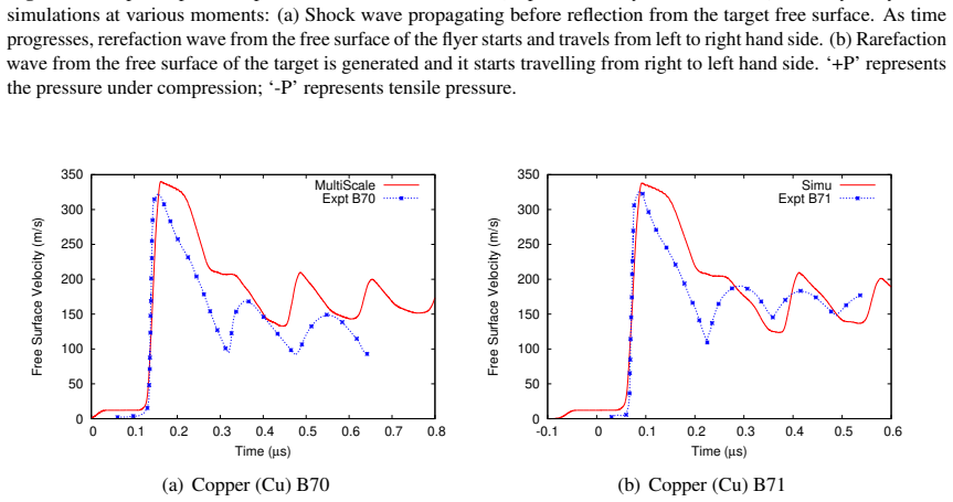
The load-bearing object is the Average Void Growth in a Fluid Element (AVGFE) model, an averaging rule that condenses the void-growth behavior of 23 distinct bicrystal grain boundaries into a single NAG fracture parameter set for a hydrodynamic cell. Around it sits the three-stage machinery the thesis uses: MD triaxial-expansion runs at strain rate $5\times10^9$ s$^{-1}$ that track void volume fraction against tensile pressure; a particle-swarm optimizer that fits the five NAG material parameters; and a 1D Lagrangian hydrodynamic code with Steinberg-Guinan strength and NAG damage that outputs free-surface velocity. AVGFE's job is to decide how the individual boundary responses combine, which is the step that the thesis argues makes the difference between single-crystal and polycrystal predictions.
What would settle it
Run full polycrystalline MD simulations of a representative volume with a known grain size distribution and compare the void-volume-fraction-versus-pressure curve at strain rate $5\times10^9$ s$^{-1}$ with the AVGFE-blended NAG prediction; if the curves differ by more than the claimed tolerance, the averaging rule fails. Directly, perform flyer-plate experiments on aluminum samples with strongly different grain size distributions at the same three velocities and check whether a single blended parameter set can fit all of them within 6%.
Extended reading notes
Core claim
The central claim, stated on the paper's own terms, is that a multiscale chain of methods can carry grain-boundary-specific atomistic information into macroscopic hydrodynamics and accurately predict spall. The chain has three links: MD simulations of triaxial expansion of 11 symmetric tilt and 12 symmetric twist aluminum bicrystals provide void-volume-fraction versus pressure data; a particle-swarm optimizer fits the five NAG coefficients for each boundary; and the new Average Void Growth in a Fluid Element rule maps the 23 parameter sets into the single fluid element of a 1D Lagrangian hydrodynamics code with a Steinberg-Guinan strength model and NAG fracture. The validation is flyer-plate impact on aluminum at 518, 1588, and 2275 m/s: the simulated temporal free-surface velocity curves match the measured profiles, with spall strength deviations bounded by 2.15%, 2.9%, and 6.0%. A second claim of the thesis is that for aluminum bicrystals the peak tensile stress is not the same as the spall strength read from the free-surface velocity profile, and that phase transitions near grain boundaries lower spall strength at high particle velocity while grain-boundary plasticity delays spallation.
Load-bearing premise
The load-bearing premise is that the AVGFE averaging rule can represent a polycrystalline hydrodynamic cell by a single blended NAG parameter set from 23 symmetric bicrystals, with no explicit treatment of grain size distribution, triple junctions, or texture.
Editorial extensions
If this is right
- If the central claim is correct, spall strength and thickness for a polycrystalline aluminum plate can be computed from bicrystal MD data rather than from a new flyer-plate experiment, for impact velocities inside the validated range.
- The NAG parameter sets for the 23 bicrystals become reusable material data: the same fits can be fed into hydrodynamic simulations with different flyer thicknesses or target geometries.
- The thesis's demonstration that peak tensile stress overestimates spall strength in Al bicrystals implies that published MD spall studies reporting only peak stress should be treated as upper bounds.
- The shock-Hugoniot results for Cu, Al, and Ni, mostly under 6% deviation from experiments, support the use of the same EAM potentials for high-pressure, high-strain-rate atomistic studies.
Reading between the lines
- Beyond the paper, the AVGFE rule suggests a testable route to microstructure-aware continuum damage: instead of one blended parameter set per cell, a cell could carry a distribution of NAG sets representing different boundary populations, and the prediction could be compared with the single-set result on the same three experiments.
- Whether 23 symmetric bicrystals are sufficient for a general polycrystal is an inference the paper does not prove; a natural check is to build bicrystals with random misorientation distributions or explicit triple junctions and see whether AVGFE predictions shift by more than the claimed 2–6%.
- The transferability of NAG coefficients fitted at constant triaxial strain rate to the one-dimensional-strain shock state is the step most in need of independent testing, for example by feeding the same parameters into 2D or 3D hydrodynamic simulations and comparing spall morphology.
Editorial analysis
A structured set of objections, weighed in public.
Referee Report
Summary. This manuscript (a Ph.D. thesis posted on arXiv) presents a multiscale pipeline that combines molecular dynamics, particle swarm optimization, and one-dimensional hydrodynamics with a nucleation-and-growth (NAG) void model. Chapter 3 validates EAM potentials for Cu, Al, and Ni by comparing MD shock Hugoniots with first-principles data and experiments. Chapter 4 fits NAG parameters from MD triaxial expansion and uses them in hydrodynamic simulations to obtain single-crystal spall strengths. Chapter 5 reports MD flyer-impact simulations across ten Al symmetric tilt and twist bicrystals. Chapter 6 extends the multiscale approach to polycrystalline Al by fitting NAG parameters for 23 bicrystals and introducing the AVGFE averaging scheme, claiming spall-strength deviations of 2.15%, 2.9%, and 6.0% against three flyer-plate experiments and spall-thickness deviations of 2.4–4.0%.
Significance. If the central polycrystal claim holds, the paper would be valuable: it offers a concrete route from atomistic, grain-boundary-specific information to macroscopic spall prediction without fitting directly to the experimental spall strengths. The single-crystal Hugoniot comparisons in Chapter 3 are systematic, the PSO code is validated on standard test functions, and the bicrystal grain-boundary energies reproduce literature values. The single-crystal multiscale simulations also improve on earlier published results for Cu, Nb, and Mo. However, the polycrystal result is not currently assessable because the AVGFE rule, which is the only new element connecting 23 bicrystal parameter sets to one hydrodynamic cell, is never defined. The reported 2–6% agreement therefore cannot yet be distinguished from a posteriori fitting.
major comments (4)
- [§6.2/§6.3, Tables 6.2–6.4] The AVGFE model, which is the load-bearing element of the polycrystal claim, is never defined. The text states that "An Average Void Growth in a Fluid Element (AVGFE) model is proposed" but gives no formula, weighting scheme, algorithm, or pseudo-code; Table 6.4 compares AVGFE with AMEAN without defining either method. Since the central 2–6% spall-strength agreement is produced by this averaging step, the reader cannot rule out that the averaging was chosen after seeing the experimental FSV curves. Please provide the explicit AVGFE rule, its derivation or physical motivation, and a demonstration that its parameters (or weights) are not adjusted to force agreement with the three experiments.
- [§6.1/§6.3, Table 6.1] The manuscript asserts that 11 STGB and 12 STwGB bicrystals represent the experimental polycrystalline Al, but it gives no justification for this sampling with respect to grain-size distribution, triple junctions, texture, or the relative area/volume of different GB types. Because the AVGFE result depends on which bicrystals are included and how they are combined, the reported accuracy is not a robust prediction unless the sensitivity of the final FSV and spall strength to the GB ensemble is demonstrated. A leave-one-out or re-sampling test over the 23 bicrystals would be appropriate.
- [§4.3.3 and §6.3.3, Eq. (4.1b)] The single-crystal Al multiscale simulations in Chapter 4 show a spurious FSV oscillation period, and the authors state that the period deviation "needs further investigation"; large spall-thickness deviations of 22–24% are reported for Cu and Mo. The polycrystal chapter then reports spall-thickness deviations of only 2.4–4.0% using the same hydrodynamic equations and NAG model. Since AVGFE only modifies the five NAG coefficients and cannot change the elastic-wave transit time that controls Tf in Eq. (4.1b), the mechanism by which averaging restores correct FSV timing needs explanation; otherwise the improved thickness numbers may be an artifact of the unstated averaging or of a different fracture-location criterion.
- [§4.2.1 and §2.3.3] The NAG parameters are fitted to MD triaxial deformation at a constant strain rate of 5×10^9 s^-1 and then applied to 1D shock hydrodynamic simulations in which the loading is uniaxial and the strain-rate history varies in space and time. The manuscript does not state whether the NAG parameters depend on strain rate or why isotropic-expansion constitutive data transfer to the uniaxial-strain spall plane. Please report the strain-rate history near the spall plane in the HD simulations and show that it overlaps the MD fitting regime, or justify the transfer explicitly through the pressure-threshold structure of the NAG equations.
minor comments (5)
- [§3.3.1, Table 3.1] The text says errors are "mostly <6%", but the MD value for Al C is 5777 m/s against an experimental value of 5426 m/s, which is a relative error of about 6.5%; please reconcile or restate the claim as applying to the other parameters.
- [§4.3.2 and elsewhere] There are numerous typos, including "molydbenum", "Surace", "coalascence", and "themodynamic"; a careful proofread is needed.
- [§5 and §6] The notation for grain-boundary types is inconsistent (STGB/STwGB in Chapter 5 but ASTGB/ASTwGB in the abbreviations list); please unify the terminology.
- [Table 6.1] Reporting the number of atoms for each bicrystal simulation would improve reproducibility and allow readers to verify finite-size convergence.
- [§2.3.3, Eq. (2.17)] The symbol Vsim is used in the NAG nucleation equation as if it were known to the hydrodynamic code, but Vsim is defined later as the MD simulation volume; please define the corresponding quantity in the hydrodynamic cell and use distinct notation.
Circularity Check
No demonstrated circularity: NAG parameters are fitted to MD void-growth data, not to the experimental spall strengths, but the central AVGFE averaging rule is never defined, leaving the polycrystal validation unauditable.
full rationale
The multiscale chain is not shown to be circular by the paper's own equations. NAG parameters are obtained by PSO fitting to MD triaxial-expansion void-volume/pressure data (Ch. 4, Sec. 4.2.2 and Ch. 6, Sec. 6.3.2), not to the experimental free-surface velocity or spall-strength values. The hydrodynamic simulations then use those NAG parameters in a separate 1D-HD code (Ch. 2, Sec. 2.3) and compare FSV profiles with external experiments (Kanel, Asay, Anton et al.). That is a genuine MD-to-continuum transfer with independent experimental validation, so the main 'prediction' does not reduce by construction to its fitting inputs. The single-crystal results show 8–15% deviations, which further indicates the comparison is not trivially forced. The principal concern is the AVGFE averaging step: it is named in the abstract and Ch. 6 ('An Average Void Growth in a Fluid Element (AVGFE) model is proposed'), and Tables/Figures compare AVGFE with AMEAN (Table 6.4, Fig. 6.8), but no formula, weighting, or algorithm is given in the visible text. Because AVGFE is the load-bearing bridge from 23 bicrystal NAG fits to the polycrystal hydrodynamic cell, the absence of its definition is an omitted-proof/auditability gap: if the averaging weights had been chosen using the three experimental FSV curves, the reported 2.15%, 2.9%, and 6.0% agreement would be partly circular. However, the text contains no quote or equation showing such fitting, so I do not classify it as demonstrated circularity. The self-adaptation of chapters from the author's published works (e.g., Ref. [30], [98]) is normal and not load-bearing in the sense of importing an external uniqueness theorem; the cited works contain the same proposed method rather than an independent justification of it. Overall, the central claim has independent content, but the undefined AVGFE rule prevents full verification that the polycrystal validation is non-circular.
Assumptions & free parameters
free parameters (4)
- NAG coefficients (N0_dot, P1, Pn0, Pg0, eta) per crystal =
Table 4.1 for single crystals; Table 6.2 for 23 bicrystals
- Shock Hugoniot coefficients C and S for Cu, Al, Ni =
Table 3.1; e.g., Ni S = 1.21
- Strain-rate law coefficients a,b and P0,P1,tau0,epsilon0 =
a=0.335, b=0.133; P0=2.76 GPa, P1=5.326 GPa, tau0=1.272e-8 s, epsilon0=2.64
- AVGFE averaging weights or rule =
Not specified in visible text
assumptions (6)
- domain assumption EAM potentials transferable to high pressure and high strain rate
- domain assumption NAG/DFRACT model is an adequate macroscopic void-nucleation-growth description
- domain assumption MD triaxial expansion at constant strain rate 5e9 s^-1 captures local tensile loading relevant to plate-impact spall
- ad hoc to paper AVGFE averaging over GB types reproduces polycrystal behavior
- domain assumption Steinberg-Guinan and polynomial EOS coefficients from literature valid for aluminum
- standard math Rankine-Hugoniot and conservation equations
invented entities (1)
-
AVGFE (Average Void Growth in a Fluid Element) averaging scheme
Cite this review
Pith. "Pith review of Multi-scale modeling of high strain rate deformation and spall fracture in poly-crystalline metals." pith.science (2026). https://pith.science/paper/V6HL7CQF
@misc{pith2026260810734,
  author       = {Pith},
  title        = {Pith review of: Multi-scale modeling of high strain rate deformation and spall fracture in poly-crystalline metals},
  year         = {2026},
  howpublished = {\url{https://pith.science/paper/V6HL7CQF}},
  note         = {Machine review of arXiv:2608.10734}
}
abstract
This thesis utilizes a multiscale method by connecting molecular dynamics (MD) based information to hydrodynamic macroscopic calculations for investigating the shock response and spallation of metals. First, shock propagation in Cu, Al, and Ni single crystals is simulated up to $100$ GPa at strain rates $>10^6$ s$^{-1}$. Shock-Hugoniot ($U_s$-$U_p$) relations agree strongly with experiments (error $<6\%$); the Foiles EAM potential shows the least deviation for Ni. Second, a multiscale framework linking MD atomic void kinetics to hydrodynamic macro-calculations is established. Using particle swarm optimization (PSO), Nucleation and Growth (NAG) parameters are extracted for Cu, Nb, Mo, and Al, yielding free surface velocity (FSV) profiles matching experiments within $8\%$ for Al. Third, deformation across ten Al tilt (STGB) and twist (STwGB) bicrystals at rates of $10^{10}$-$10^{11}$ s$^{-1}$ proves that threshold spallation depends on boundary misorientation. Phase transitions near GBs lower spall strength at high $U_p$, whereas GB plasticity prolongs pull-back and delays spallation (e.g., $14.2^\circ$ STwGB). FSV methods are found to underestimate true peak tensile strength. Fourth, the framework is extended to polycrystals via 11 STGB and 12 STwGB configurations. Voids consistently nucleate at weakened GBs. Unique NAG parameters are fitted using PSO for all 23 bicrystals. An Average Void Growth in a Fluid Element (AVGFE) model is introduced to map these distinct boundary properties into 1D hydrodynamic codes. The combined model is validated against empirical Al flyer impacts at $518$, $1588$, and $2275$ m/s. The simulated temporal FSV curves mirror experiments, with spall strength deviations tightly bounded within $2.15\%$, $2.9\%$, and $6.0\%$, respectively, and spall thickness deviations within $2.4$-$4.0\%$.
Figures


Figures from the paper (34 more)




Reference graph
Works this paper leans on
-
[1]
Graham, Solids Under High-Pressure Shock Compression, Springer, 1993
R. Graham, Solids Under High-Pressure Shock Compression, Springer, 1993. ← page 1
1993
-
[2]
M. A. Meyers, Dynamic Behavior of Materials, John Wiley & Sons, Inc., New York, 1994. ←pages 1, 2, 3, 19, 23, 24, 28, 29, 30, 45, 53, 54, and 73
1994
-
[3]
Johnson, W
G. Johnson, W. Cook, Fracture characteristics of three metals subjected to various strains, strain rates, temperatures and pressures, Eng. Fract. Mech. 21 (1985) 31–48.←pages 1, 30, and 41
1985
-
[4]
V . E. Fortov, V . V . Kostin, S. Eliezer, Spallation of metals under laser irradiation, Journal of Applied Physics 70 (1991) 4524. doi:10.1063/1.349087. ← pages 1, 2, 41, 52, and 53
-
[5]
Moshe, S
E. Moshe, S. Eliezer, E. Dekel, A. Ludmirsky, Z. Henis, M. Werdiger, I. B. Goldberg, An increase of the spall strength in aluminum, copper, and metglas at strain rates larger than 107 s−1, Jnl. of Applied Physics 83 (1998) 4004.←pages 1, 2, 41, 52, and 53
1998
-
[6]
Moshe, S
E. Moshe, S. Eliezer, Z. Henis, M. Werdiger, E. Dekel, Y . Horovitz, S. Maman, I. B. Goldberg, D. Eliezer, Experimental measurements of the strength of metals approaching the theoretical limit predicted by the equation of state, Applied Physics Letters 76 (2000) 1555–1557.←pages 1, 2, 41, 52, and 53
2000
-
[7]
G. I. Kanel, S. V . Razorenov, K. Baumung, J. Singer, Dynamic yield and tensile strength of aluminum single crystals at temperatures up to the melting point, Jnl. of App. Phy. 90 (2001) 136–143. doi:doi.org/10.1063/1.1374478. ← pages 1, 30, 35, 36, 38, 39, 41, 52, and 53
-
[8]
Seaman, D
L. Seaman, D. R. Curran, D. A. Shockey, Computational models for ductile and brittle fracture, Jnl. Appl. Phys. 47 (1976) 4814.←pages 1, 30, and 41
1976
Show all 113 references
-
[9]
D. R. Curran, L. Seaman, D. A. Shockey, Dynamic failure of solids, Phys. Rep. 147 (5-6) (1987) 253–388.←pages 1, 13, 30, 33, and 41
1987
-
[10]
J. N. Johnson, G. Gray, N. Bourne, Effect of pulse duration and strain rate on incipient spall fracture in copper, Jnl. Appl. Phys. 86 (1999) 4892–4901.←pages 1, 30, and 41
1999
-
[11]
V . R. Ikkurthi, S. Chaturvedi, Use of different damage models for simulating impact-driven spallation in metal plates, Int. J. Impact Engg. 30 (2004) 275–301. ← pages 1, 2, 30, 33, and 41
2004
-
[12]
I. R. Vatne, A. Stukowski, C. Thaulow, E. Østby, J. Marian, Three-dimensional crack initiation mechanisms in BCC-Fe under loading modes I, II and III, Materials Science and Engineering: A 560 (2013) 306–314. doi:10.1016/j.msea.2012.09.071. ← pages 1 and 41
2013 doi
-
[13]
Madhavan, V
S. Madhavan, V . Mehra, S. Pahari, S. Ghosh, C. D. Sijoy, S. Chaturvedi, Buckling and longitudinal cracks in electromagnetically accelerated hollow cylinders, International Journal of Fracture 193 (2015) 1–16.doi:10.1007/s10704-015-0010-9.←pages 1 and 41
2015 doi
-
[14]
T. H. Antoun, L. Seaman, D. R. Curran, Dynamic failure of materials: V olume 2-compilation BIBLIOGRAPHY 77 of russian spall data, Tech. Rep. DSWA-TR-96-77-V2, URL active as on 30th Mar 2023 (1998). URL https://apps.dtic.mil/sti/pdfs/ADA362759.pdf← pages 1, 30, 35, 36, 37, 38, ...
1998
-
[15]
H. E. Lorenzana, J. F. Belak, K. S. Bradley, Shocked materials at the intersection of experiment and simulation, Scientific Modelling and Simulations. 15 (2008) 159–186. doi:10.1007/s10820-008-9107-z.←page 1
2008 doi
-
[16]
J. R. Asay, L. M. Barker, Interferometric mmeasurement of shock-induced particle velocity and spatial variations of particle velocity, Journal of Applied Physics 45 (1974) 2540–2546. ←pages 1 and 35
1974
-
[17]
D. D. Bloomquist, S. A. Sheffield, Optically recording interferometer for velocity mea- surements with subnanosecond resolution, Journal of Applied Physics 54 (1983) 1717. doi:10.1063/1.332222.←pages 1 and 35
1983 doi
-
[18]
R. E. Duff, F. S. Minshall, Investigation of a Shock-Induced Transition in Bismuth, Physical Review 108 (5) (1957) 1207–1212.←page 1
1957
-
[19]
S. G. Srinivasan, M. I. Baskes, G. J. Wagner, Spallation of single crystal nickel by void nucleation at shock induced grain junctions, Journal of Materials Science 41 (2006) 7838– 7842.←pages 1 and 41
2006
-
[20]
S. G. Srinivasan, M. I. Baskes, G. J. Wagner, Atomistic simulations of shock induced microstructural evolution and spallation in single crystal nickel, Journal of Applied Physics 101 (2007) 043504.doi:10.1063/1.2423084.←pages 1, 3, 4, 41, 42, 52, and 53
2007 doi
-
[21]
Rawat, M
S. Rawat, M. Warrier, S. Chaturvedi, V . Chavan, Effect of material damage on the spallation threshold of single crystal copper: a molecular dynamics study, Modelling and Simulation in Material Science and Engineering 20 (2012) 015012.←pages 1, 21, 22, 41, and 60
2012
-
[22]
D. D. Jiang, J. L. Shao, B. Wu, P. Wang, A. M. He, Sudden change of spall strength induced by shock defects based on atomistic simulation of single crystal aluminum, Scripta Materialia 210 (2022) 114474. doi:https://doi.org/10.1016/j.scriptamat.2021. 114474.←pages 1, 4, 41, 51, and 54
2022 doi
-
[23]
S. J. Fensin, S. M. Valone, E. K. Cerreta, G. T. Gray, Influence of grain boundary properties on spall strength: Grain boundary energy and excess volume, Journal of Applied Physics 112 (2012) 083529.←pages 1, 4, 41, and 51
2012
-
[24]
Y . Zhu, J. Hu, S. Huang, J. Wang, G. Luo, Q. Shen, Molecular dynamics simulation on spal- lation of [111] Cu/Ni nano-multilayers: V oids evolution under different shock pulse duration, Computational Materials Science 202 (2022) 110923. doi:10.1016/j.commatsci.2021. 110923.←pa...
2022 doi
-
[25]
M. L. Wilkins, Computer Simulation of Dynamic Phenomena, Springer, 1999. ← pages 2, 12, 13, 19, and 30
1999
-
[26]
W. J. Murphy, A. Higginbotham, G. K. et al., The strength of single crystal copper under uniaxial shock compression at 100 GPa, Journal of Physics: Condensed Matter 22 (6) (2010) 065404.doi:10.1088/0953-8984/22/6/065404.←page 2
2010 doi
-
[27]
Rawat, V
S. Rawat, V . R. Ikkurthi, M. Warrier, S. Chaturvedi, Multiscale simulations of damage of perfect crystal Cu at high strain rates, PRAMANA Journal of Physics 83 (2) (2014) 265–272. ←pages 2, 3, 7, 33, 61, 68, and 73
2014
-
[28]
← pages 2, 3, 5, 7, 30, 35, 37, BIBLIOGRAPHY 78 38, 39, 40, 61, 68, and 73
V .R.Ikkurthi, H.Hemani, R.Sugandhi, S.Rawat, P.Pahari, M.Warrier, S.Chaturvedia, Multi- scale computational approach for modelling spallation at high strain rates in single-crystal materials, Procedia Engineering 173 (2017) 1177–1184. ← pages 2, 3, 5, 7, 30, 35, 37, BIBLIOGRA...
2017
-
[29]
Madhavan, V
S. Madhavan, V . R. Ikkuthi, P. V . Laxminarayana, M. Warrier, Multiscale modelling to estimate spall parameters in metallic single crystals, in: Proc. ICONS2018, International Conference on Structural Integrity, IITM, Chennai, India, 2018. doi:https://doi.org/ 10.48550/arXiv....
-
[31]
Madhavan, V
S. Madhavan, V . Mishra, P. V . L. Narayana, M. Warrier, Dynamic Response of Single Crystal Al, Cu & Ni Upon Impact : MD and Ab-Initio Calculations, Journal of Dynamic Behavior of Materials 9(1) (2023) 24–35. doi:10.1007/s40870-022-00356-5 . ← pages 2, 5, 19, 22, 23, 24, 25, 2...
2023 doi
-
[32]
B. L. Holian, Modeling shock-wave deformation via molecular dynamics, Physical Review A 37 (7) (1988) 2562–2568.doi:10.1103/PhysRevA.37.2562.←pages 3 and 20
1988 doi
-
[33]
E. M. Bringa, J. U. Cazamias, P. Erhart, et. al, Atomistic shock Hugoniot simulation of single-crystal copper, Journal of Applied Physics 97 (7) (2004) 3793–3799. doi:10.1063/ 1.1789266.←pages 3 and 20
2004
-
[34]
H. N. Jarmakani, E. M. Bringa, P. Erhart, B. A. Remington, Y . M. Wang, N. Q. V o, M. A. Meyers, Molecular dynamics simulations of shock compression of nickel: From monocrys- tals to nanocrystals, Acta Materialia 56 (2008) 5584–5604. ← pages 3, 20, 27, 28, 29, and 73
2008
-
[35]
L. Hai, H. Jie, Z. Zhi-xuan, M. Zhao-xia, Atomistic simulations of elastic-plastic deformation in nickel single crystal under shock loading, Procedia Engineering 204 (2017) 397–404. ←pages 3, 20, 27, 28, 29, and 73
2017
-
[36]
J. Choi, S. Yoo, S. Song, J. S. Park, K. Kang, Molecular dynamics study of Hugoniot relation in shocked nickel single crystal, Journal of Mechanical Science and Technology 32 (7) (2018) 7983.←pages 3, 20, 27, 28, 29, and 73
2018
-
[37]
Sugandhi, M
R. Sugandhi, M. Warrier, S. Chaturvedi, Identification of best parameters of void nucleation and growth model using particle swarm technique., Applied Soft Computing 35 (2015) 113–122.←pages 3 and 10
2015
-
[38]
Adlakha, M
I. Adlakha, M. A. Tschopp, K. N. Solanki, The role of grain boundary structure and crystal orientation on crack growth asymmetry in aluminum, Materials Science and Engineering: A 618 (2014) 345–354.doi:10.1016/j.msea.2014.08.083.←pages 3, 4, and 41
2014 doi
-
[39]
Zhang, K
X. Zhang, K. Wang, W. Zhu, J. Chen, M. Cai, S. Xiao, H. Deng, W. Hu, Effect of grain boundaries on shock-induced phase transformation in iron bicrystals, Jnl. of Applied Physics 123 (2018) 045105.doi:10.1063/1.5003891.←pages 4 and 41
2018 doi
-
[40]
X. Long, X. Liu, W. Zhang, Y . Peng, G. Wang, Shock deformation and spallation of Cu bicrystals with (111) twist grain boundaries, Computational Materials Science 173 (2020) 109411.doi:10.1016/j.commatsci.2019.109411.←pages 4, 41, 51, 56, and 59
2020
-
[41]
E. Q. Lin, H. J. Shi, L. S. Niu, E. Z. Jin, Shock response of copper bicrystals with a Σ3 asymmetric tilt grain boundary, Computational Materials Science 59 (2012) 94–100. doi: https://doi.org/10.1016/j.commatsci.2012.02.025.←pages 4, 41, 42, and 51
2012 doi
-
[42]
S. N. Luo, T. C. Germann, D. L. T. Q. An, Shock wave loading and spallation of copper bicrystals with asymmetric Σ3 <110> tilt grain boundaries, Jnl. Appl Phys. 108 (2010) BIBLIOGRAPHY 79 093526.doi:10.1063/1.3506707.←pages 4 and 41
2010 doi
-
[43]
W. Z. Han, Q. An, S. N. Luo, T. C. Germann, D. L. Tonks, W. A. Goddard, Deformation and spallation of shocked Cu bicrystals with Σ 3 coherent and symmetric incoherent twin boundaries, Phys Rev B 85 (2012) 024107. doi:10.1103/Physrevb.85.024107. ← pages 4 and 41
2012 doi
-
[44]
S. J. Fensin, S. M. Valone, E. K. Cerreta, et.al., Effect of grain boundary structure on plastic deformation during shock compression using molecular dynamics, Model Simul Mater Sci. 21 (2013) 015011.doi:10.1088/0965-0393/21/1/015011.←pages 4 and 41
2013 doi
-
[45]
Y . Zhou, Z. Yang, Z. Lu, Dynamic crack propagation in copper bicrystals grain boundary by atomistic simulation, Materials Science and Engineering: A 599 (2014) 116–124. ← pages 4 and 41
2014
-
[46]
L. A. Barrales-Mora, Y . Tokuda, D. A. Molodov, S. Tsurekawa, On incipient plasticity in the vicinity of grain boundaries in aluminum bicrystals: Experimental and simulation nanoindentation study, Materials Science and Engineering: A 828 (2021) 142100. doi: 10.1016/j.msea.2021...
2021
-
[47]
W. W. Pang, P. Zhang, G. Zhang, A. Xu, X. Zhao, Dislocation creation and void nucleation in FCC ductile metals under tensile loading: A general microsopic picture, Scientific Reports 4 (2014) 6981.←page 4
2014
-
[48]
H. V . Swygenhoven, P. M. Derlet, A. G. Froseth, Nucleation and propagation of dislocatiosn in nanocrystalline fcc metals, Acta Materialia 54 (2005) 1975–1983.←pages 4 and 59
2005
-
[49]
D. E. Spearot, K. L. Jacob, D. L. McDowell, Nucleation of dislocations from [001] bicrystal interfaces in aluminum, Acta Materialia 53 (2005) 3579–3589.←pages 4, 56, and 59
2005
-
[50]
Dremov, A
V . Dremov, A. Petrovtsev, P. Sapozhnikov, M. Smirnova, Molecular dynamics simulations of the initial stages of spall in nanocrystalline copper, Phy. Rev. B 74 (2006) 144110.← pages 4 and 59
2006
-
[51]
Plimpton, Fast parallel algorithms for short range molecular dynamics, Journal of Compu- tational Physics 117 (1995) 1–19.←pages 5, 7, 21, 42, 86, and 87
S. Plimpton, Fast parallel algorithms for short range molecular dynamics, Journal of Compu- tational Physics 117 (1995) 1–19.←pages 5, 7, 21, 42, 86, and 87
1995
-
[52]
Rawat, Behavior of solids under high strain rate deformation, Ph.D
S. Rawat, Behavior of solids under high strain rate deformation, Ph.D. thesis, (2012) pp 32-38 chapter 3.3; URL active as on 30th Mar 2023. URL http://www.hbni.ac.in/phdthesis/phys/PHYS01200704031.pdf← pages 7, 9, 30, 33, 35, 39, and 40
2012
-
[53]
Lammps benchmarks, https://www.lammps.org/bench.html, URL active as on 30th Mar 2023.←page 7
2023
-
[54]
S. M. Foiles, M. I. Baskes, M. S. Daw, Embedded-atom-method functions for the fcc metals Cu, Ag, Au, Ni, Pd, Pt and their alloys, Physical Review B 33 (1986) 7983. ← pages 8, 9, 20, 21, 25, 27, 28, 29, 31, 73, and 87
1986
-
[55]
Interatomic potentials overview, https://www.ctcms.nist.gov/potentials, URL ac- tive as on 30th Mar 2023.doi:10.18434/m37.←pages 8, 87, 88, and 89
2023 doi
-
[56]
Mishin, D
Y . Mishin, D. Farkas, M. J. Mehl, D. A. Papaconstantopoulos, Interatomic potentials for monoatomic metals from experimental data and ab initio calculations, Physical Review B 59 (5) (1999) 3393–3407.←pages 8, 9, 42, 60, and 89
1999
-
[57]
X. W. Zhou, R. A. Johnson, H. N. G. Wadley, Misfit-energy-increasing dislocations in vapor-deposited CoFe/NiFe multilayers, Physical Review B 69 (14) (2004) 144113. doi: {10.1103/physrevb.69.144113}.←pages 8, 9, 31, and 88
2004 doi
-
[58]
Kittel, Introduction to Solid State Physics, 8th Edition, John Wiley & Sons, 2005
C. Kittel, Introduction to Solid State Physics, 8th Edition, John Wiley & Sons, 2005. ← pages 8 and 9. BIBLIOGRAPHY 80
2005
-
[59]
D. B. Marghitu, Mechanical Engineer’s handbook, Academic Press, 2001. ← pages 8 and 9
2001
-
[60]
Tzanetakis and J
P. Tzanetakis and J. Hillairet and G. Revel, The Formation Energy of Vacancies in Aluminium and Magnesium, physica status solidi B 75 (2) (1976) 433–439.←page 9
1976
-
[61]
McGervey, W
J. McGervey, W. Triftshuser, Vacancy-formation energies in copper and silver from positron annihilation, Physics Letters A 44 (1) (1973) 53–54. doi:https://doi.org/10.1016/ 0375-9601(73)90957-2.←page 9
1973
-
[62]
T. R. Mattsson, N. Sandberg, R. Armiento, A. E. Mattsson, Quantifying the anomalous self-diffusion in molybdenum with first-principles simulations, Phys. Rev. B 80 (22) (2009) 224104.doi:10.1103/PhysRevB.80.224104.←page 9
2009 doi
-
[63]
Wolff, M
J. Wolff, M. Franz, J.-E. Kluin, D. Schmid, Vacancy formation in nickel and α-nickel- carbon alloy, Acta Materialia 45 (11) (1997) 4759–4764. doi:https://doi.org/10. 1016/S1359-6454(97)00112-2.←page 9
1997
-
[64]
K. W. Jacobsen, J. K. Norskov, M. J. Puska, Interatomic interactions in the effective-medium theory, Physical Review B 35 (1987) 7423.←pages 8, 21, 29, 31, and 73
1987
-
[65]
Nordlund, Basics of md, initialization, time step choice, speedup methods, http://beam
K. Nordlund, Basics of md, initialization, time step choice, speedup methods, http://beam. helsinki.fi/~knordlun/atomistiset/lecture2.ps.gz, URL active as on 30th Mar 2023 (2000).←page 9
2000
-
[66]
Y . Shi, R. Eberhart, A modified particle swarm optimizer, in: Proc. of IEEE international conference on evolutionary computation. IEEE world congress on computational intelligence (Cat. No. 98TH8360), IEEE, 1998, pp. 69–73.←pages 10 and 11
1998
-
[67]
X. S. Yang, Test problems in optimization, John Wiley & Sons, 2010.←page 11
2010
-
[68]
M. L. Wilkins, Calculation of elastic-plastic flow, in: B. Alder (Ed.), Methods in Computa- tional Physics, V ol. 3, 1964, pp. 211–263.←pages 12, 13, 14, 15, 16, and 30
1964
-
[69]
D. J. Steinberg, S. G. Cochran, M. W. Guinan, A constitutive model for metals applicable at high-strain rate, Journal of Applied Physics 51 (3) (1980) 1498–1504. ← pages 13 and 30
1980
-
[70]
D. J. Steinberg, Constitutive model used in computer simulation of time-resolved, shock- wave data, International Journal of Impact Engineering 5 (1) (1987) 603–611, hyperve- locity Impact Proceedings of the 1986 Symposium. doi:https://doi.org/10.1016/ 0734-743X(87)90075-3.←pa...
1987
-
[71]
R. G. McQueen, S. P. Marsh, J. W. Taylor, J. N. Fritz, W. J. Carter, The equation of state of solids from shock wave studies, High velocity impact phenomena 293 (1970) 294–417. ←pages 15 and 17
1970
-
[72]
S. P. Marsh, LASL Shock Hugoniot Data, University of california press, Berkeley, 1980. ←pages 15, 17, 23, 24, 26, 27, 28, and 73
1980
-
[73]
Zel’dovich, Y
Y . Zel’dovich, Y . Raizer, Physics of Shock Waves and High-Temperature Hydrodynamic Phenomena, Dover Books on Physics, Dover Publications, New York, 2002. URLhttps://books.google.co.in/books?id=zVf27TMNdToC←page 19
2002
-
[74]
A. C. Mitchell, W. J. Nellis, Shock compression of aluminum, copper, and tantalum, Journal of Applied Physics 52 (5) (1981) 3363–3374.←pages 19, 23, 24, 28, 30, and 73
1981
-
[75]
A. D. Chijioke, W. J. Nellis, I. F. Silvera, High-pressure equations of state of Al, Cu, Ta and W, Journal of Applied Physics 98 (2005) 073526.←page 19
2005
-
[76]
M. O. Steinhauser, S. Hiermaier, A review of computational methods in materials science: Examples from shock-wave and polymer physics, Int. J. Mol. Sci. 10 (12) (2009) 5135–5216. ←page 20. BIBLIOGRAPHY 81
2009
-
[77]
Y . Y . Ju, Q. M. Zhang, Z. Z. Gong, G. F. Ji, L. Zhou, Molecular dynamics simulation of shock melting of aluminum single crystal, Journal of Applied Physics 114 (2013) 093507. ←page 20
2013
-
[78]
A. A. Selezenev, V . K. Golubev, A. Y . Aleinikov, O. I. Butney, R. A. Barabanov, B. L. V oronin, Molecular dynamics simulation of shock wave compression of metals, AIP Conference Proceedings 620 (2002) 374–377.←page 20
2002
-
[79]
A. C. Mitchell, W. J. Nellis, J. A. Moriarty, R. A. Heinle, N. C. Holmes, R. E. Tipton, G. W. Repp, Equation of state of Al, Cu, Mo, and Pb at shock pressures up to 2.4 TPa (24 Mbar), Journal of Applied Physics 69 (1991) 2981–2986.←page 20
1991
-
[80]
K. D. Joshi, S. C. Gupta, S. Banerjee, Shock Hugoniot of osmium up to 800 GPa from first principles calculations, J. Phys. Condens. Matter 21 (2009) 415402(1–6).←page 20
2009
-
[81]
Gyanchandani, V
J. Gyanchandani, V . Mishra, G. K. D. S. K. Sikka, Super heavy element copernicium: Cohesive and electronic properties revisited, Solid State Communications 269 (2018) 16. ←page 20
2018
-
[82]
J. R. Taylor, An introduction to error analysis, 2nd Edition, University Science Books, Sausalito, California, 1997, Ch. 3, pp. 51–53.←page 22
1997
-
[83]
Dewaele, P
A. Dewaele, P. Loubeyre, M. Mezouar, Equations of state of six metals above 94 GPa, Physical Review B 70 (2004) 094112.←pages 23, 25, and 26
2004
-
[84]
Dewaele, M
A. Dewaele, M. Torrent, P. Loubeyre, M. Mezouar, Compression curves of transition metals in the mbar range: Experiments and projector augmented-wave calculations, Physical Review B 78 (2008) 104102.←pages 23, 25, and 26
2008
-
[85]
Akahama, M
Y . Akahama, M. Nishimura, K. Kinoshita, H. Kawamura, Y . Ohishi, Evidence of a fcc-hcp transition in aluminum at multimegabar pressure, Physical Review Letters 96 (2006) 045505. ←pages 23, 25, and 26
2006
-
[86]
J. F. Ziegler, J. P. Biersack, The stopping and range of ions in matter, in Treatise on Heavy-Ion Science, Springer (1985) 93–129.←page 25
1985
-
[87]
D. K. Belashchenko, Computer simulation of nickel and the account for electron contributions in the molecular dynamics method, High Temp. 58 (1) (2020) 64–77.←page 27
2020
-
[88]
A. Y . Dolgoborodov, S. Y . Ananev, V . V . Yakushev, Shock Hugoniot of porous nanosized nickel, J. Appl. Phys. 131 (2022) 125902.←pages 27 and 29
2022
-
[89]
S. A. Kinelovskii, K. K. Maevskii, Estimation of the thermodynamic parameters of a shock-wave action on high-porosity heterogeneous materials, Technical Phys 61 (8) (2016) 1244–1249.←pages 28 and 29
2016
-
[90]
← pages 28 and 29
The international shock-wave database (ISWdb), URL active as on 30th Mar 2023. ← pages 28 and 29
2023
-
[91]
J. A. Zukas, Introduction to Hydrocodes, Elsevier, Amsterdam, 2004.←page 30
2004
-
[92]
Eliezer, An Introduction to Equations of State: Theory and Applications, Cambridge University Press, Cambridge, 1986.←page 30
S. Eliezer, An Introduction to Equations of State: Theory and Applications, Cambridge University Press, Cambridge, 1986.←page 30
1986
-
[93]
S. V . G. Menon, B. Nayak, An equation of state for metals at high temperature and pressure in compressed and expanded volume regions, Condensed Matter 4 (3) (2019) article no. 71. doi:10.3390/condmat4030071.←page 30
2019 doi
-
[94]
X. Chen, J. R. Asay, S. K. Dwivedi, D. P. Field, Spall behavior of aluminum with varying microstructures, Journal of Applied Physics 99 (2006) 023528. doi:10.1063/1.2165409. ←pages 30, 35, 36, 38, 39, 64, 65, 66, and 69
2006 doi
-
[95]
M. R. Fellinger, H. Park, J. W. Wilkins, Force-matched embedded-atom method potential for niobium, Physical Review B 81 (14) (2010) 144119. doi:10.1103/physrevb.81.144119. BIBLIOGRAPHY 82 ←page 31
2010 doi
-
[96]
Hemani, M
H. Hemani, M. Warrier, N. Sakthivel, S. Chaturvedi, V oxel based parallel post processor for void nucleation and growth analysis of atomistic simulations of material fracture, Journal of Molecular Graphics and Modeling 50 (2014) 134–141.←page 32
2014
-
[97]
M. V . Zhernokletov, B. L. Glushak, Material Properties under Intensive Dynamic Loading, Springer, 2006.←page 41
2006
-
[98]
Madhavan, P
S. Madhavan, P. V . Laxminarayana, M. Warrier, Spall fracture in aluminum bicrystals: Molecular dynamics study, Materials Today: Proc. 87 (1) (2023) 164–169. doi:10.1016/j. matpr.2023.03.281.←pages 42, 43, 45, 47, 49, and 72
2023 doi
-
[99]
M. A. Tschopp, S. P. Coleman, D. L. McDowell, Symmetric and asymmetric tilt grain boundary structure and energy in Cu and Al (and transferability to other fcc metals), Integrating Materials and Manufacturing Innovation 4 (2015) 176–189. doi:10.1186/ s40192-015-0040-1.←pages 42...
2015
-
[100]
M. A. Tschopp, D. L. Mcdowell, Asymmetric tilt grain boundary structure and energy in copper and aluminium, Philosophical Magazine 87(25) (2007) 3871–3892. ← pages 42, 43, 60, and 62
2007
-
[101]
Q. Yin, Z. Wang, R. Mishra, Z. Xi, Atomic simulations of twist grain boundary structures and deformation behaviors in aluminum, AIP Advances 7 (2017) 015040. ← pages 42, 43, 51, 60, and 62
2017
-
[102]
Smith, J
J. Smith, J. Lacy, D. Levesque, J. Monchalin, M. Lord, Use of the Hugoniot elastic limit in laser shockwave experiments to relate velocity measurements, V ol. 1706, AIP Conf. Proc., 2016, p. 080005.doi:10.1063/1.4940537.←page 45
2016 doi
-
[103]
W. Li, E. N. Hahn, X. Yao, T. Germann, X. Zhang, Shock induced damage and fracture in SiC at elevated temperature and high strain rate, Acta Materialia 167 (2019) 51–70. doi: https://doi.org/10.1016/j.actamat.2018.12.035.←pages 49, 50, 51, and 52
2019 doi
-
[104]
Williams, C
T. Williams, C. Kelley, et.al., Gnuplot 4.6: An interactive plotting program (April 2013), http://gnuplot.sourceforge.net, URL active as on 30th Mar 2023.←page 53
2013
-
[105]
A. Stukowski, Visualization and analysis of atomistic simulation data with OVITO–the open visualization tool, Modelling and Simulation in Materials Science and Engineering 18 (1) (2009) 015012.←pages 55, 56, and 62
2009
-
[106]
Stukowski, V
A. Stukowski, V . V . Bulatov, A. Arsenlis, Automated identification and indexing of disloca- tions in crystal interfaces, Modelling and Simulation in Materials Science and Engineering (2012) 085007.←pages 56 and 62
2012
-
[107]
Sansoz, J
F. Sansoz, J. F. Molinari, Mechanical behavior of Σ tilt grain boundaries in nanoscale Cu and Al: A quasicontinuum study, Acta Materialia 53 (7) (2005) 1931–1944.←page 56
2005
-
[108]
C. D. Owen, D. J. Chapman, G. Whiteman, S. M. Millett, S. Johnson, Spall behavior of single crytal aluminum at three principal orientations, Journal of Applied Physics 122 (2017) 155102.←pages 64, 65, 66, and 69
2017
-
[109]
F. J. Zerilli, R. W. Armstrong, Dislocation mechanics based constitutive relations for material dynamics calculations, Journal of Applied Physics 61 (1987) 1816–1825. doi:doi.org/ 10.1063/1.338024.←pages 70 and 75
1987 doi
-
[110]
G. Wang, Y . Xu, Embedded-atom potential for Ni-Al alloy, V ol. 452, IOP Conf. Series: Materials Science and Engineering, 2018, p. 022025. doi:10.1088/1757-899X/452/2/ 022025.←page 89. 86 Appendix A Parameters of EAM potentials used in this work EAM potential can be expressed ...
2018 doi
-
[111]
Introduction Shockwave is produced when a material is subjected to high strain rate ( _e > 10 6/s) impact [1–5]. Computer simulation of shock is extensively performed over the several decades at macroscopic levels, with the assistance of data collected from poly-crystal [4– 6]...
-
[112]
Results from the MD andfirst principles calculations and their comparison for shock-Hugoniot condition are discussed in sec. 3. The conclusions are presented in sec. 4. https://doi.org/10.1016/j.matpr.2023.04.543 2214-7853/Copyright�2022 Elsevier Ltd. All rights reserved. Selec...
2023 doi
-
[113]
Upon reaching the free surface, each wave reflects back into the plates as rarefaction waves
Introduction Metalflyer plate impacting a metal target plate produces shock- waves that travels in both theflyer and the target in opposite directions. Upon reaching the free surface, each wave reflects back into the plates as rarefaction waves. When these two rarefaction waves m...
2023
-
[114]
When two bodies collide shockwaves are generated which travel into both the bodies and reflect as rarefaction waves from the free sur- faces
Introduction Predicting the dynamic fracture (spall) of materials subjected to high velocity impact or explosion is important for many applications. When two bodies collide shockwaves are generated which travel into both the bodies and reflect as rarefaction waves from the fre...
Reviewed August 12, 2026 · model on record in the stance chip above.
Discussion (0). Continue with ORCID to comment.