REVIEW 2 major objections 4 minor 15 references
Optical concept model of the future cosmology project BISOU
T0 review · 2 major / 4 minor · reviewed 2026-08-14 · deepseek-v4-flash
Pith's one-line read Simulations show BISOU's five-mirror Fourier-transform spectrometer keeps optical losses below 7.5% and beam pointing stable within ±0.1° across a four-times-overdrive mirror scan.
desk verdict Workmanlike optical design study for the BISOU balloon FTS; numbers are plausible but the monomode Gaussian approximation and a factor-two OPD error need attention. read the letter →
The pith
A machine-rendered reading of the paper's core claim, the machinery that carries it, and where it could break.
The reading
What carries the argument
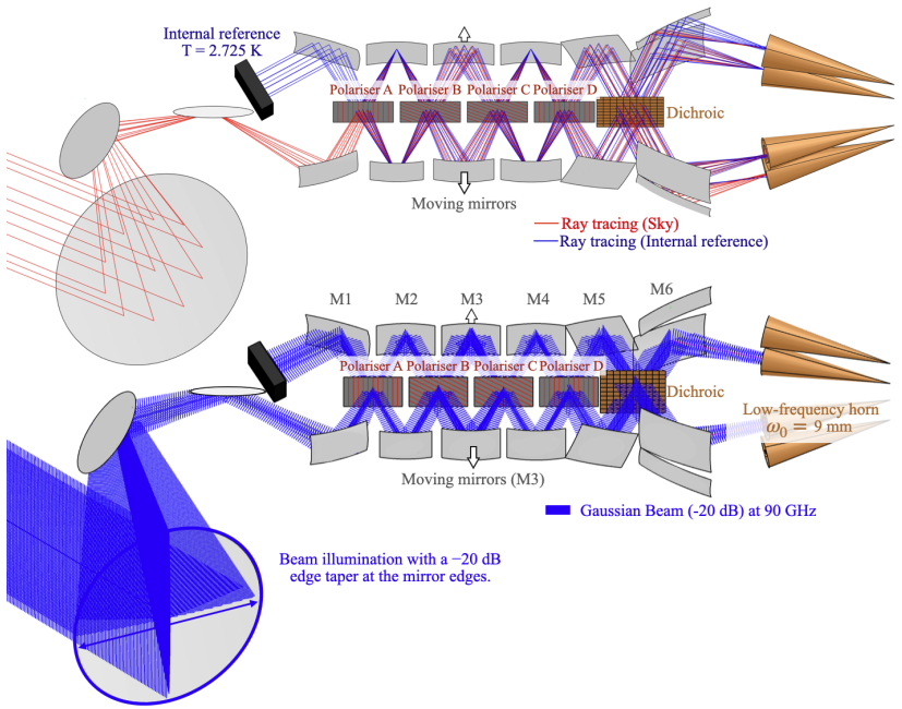
The load-bearing tool is Gaussian-beam propagation: the feedhorn is modelled as a monomode Gaussian source with a 9 mm waist at 90 GHz, and the beam envelope is carried through the optical system with physical optics. The edge taper, the chosen attenuation at each mirror's edge, is the lever that sets spillover, with −35 dB demanded on FTS mirrors to contain 98% of the beam power and −20 dB allowed on the primary to keep that mirror reasonably small. The moving-mirror scan is then tested by recomputing the propagated beam at the extremes of stroke; the Mizugushi-Dragone telescope geometry is what suppresses the cross-polarisation and astigmatism that such offsets would otherwise excite.
What would settle it
Measure the 90 GHz far-field pattern and per-mirror spillover of the actual multimode feedhorn in the cryogenic breadboard, and compare with the predicted under-0.2% FTS loss, under-7.5% total loss, ±0.1° depointing, and ≤0.5 dB directivity variation over a ±10 mm stroke; if the measured losses or beam shifts exceed these bounds, the monomode-Gaussian assumption is the point of failure.
Extended reading notes
Core claim
The central claim is that the BISOU optical concept, a five-mirror polarising Fourier-transform spectrometer with a direct view of the internal 2.7 K reference and a Gregorian telescope tuned to the Mizugushi-Dragone condition, performs acceptably at the low end of its band. The 90 GHz Gaussian beam, launched from a horn with a 9 mm waist, is kept at a −35 dB edge taper on FTS mirrors and −20 dB on the primary, so diffraction and spillover stay under control: the FTS loses under 0.2% of the power up to its first mirror and the entire chain loses under 7.5%. As the moving mirrors travel through a ±10 mm stroke, the peak beam direction moves by less than ±0.1°, the beam remains Gaussian, and directivity drops by no more than 0.5 dB at the +10 mm extreme. Because the science signal is a part-per-million-level deviation in sky brightness, a configuration whose losses are small, stable, and mostly independent of mirror position makes the measurement feasible.
Load-bearing premise
Every quantitative result rests on treating the instrument's multimode feedhorns as monomode Gaussian beams with a fixed 9 mm waist at 90 GHz, so a real horn whose radiation pattern differs could change the spillover, beam shape, and pointing numbers.
Editorial extensions
If this is right
- At the nominal ±2.5 mm stroke needed for the 15 GHz resolution, the spillover and pointing effects will be even smaller than the simulated extremes, so the design has margin.
- The five-mirror FTS with the reference imaged by the first mirror reduces optical mass while preserving the interferometric signal, which helps fit the instrument inside a standard balloon gondola.
- A beam whose direction changes by less than 0.1° across a scan provides a well-defined line of sight that can be calibrated in post-processing, so mirror motion should not dominate systematic errors.
- The small but visible asymmetry between the +10 mm and −10 mm spillover paths shows where future work on mirror shapes and alignment tolerances should focus.
Reading between the lines
- If the real multimode horn has a broader radiation pattern, the 7.5% spillover budget may grow; replacing the Gaussian source with a measured multimode pattern in the same physical-optics setup is a direct test of whether the mirrors stay large enough.
- The ±0.1° pointing shift and 0.5 dB directivity swing over the scan can be turned into an empirical calibration: a short preflight scan could map beam centroid versus mirror position, letting the data pipeline remove scan-synchronous gain modulations.
- The asymmetry between positive and negative strokes hints at a residual third-order aberration from the mirror surfaces; if it appears in breadboard measurements, an asymmetric tolerance or a slight refocus could cancel it.
Editorial analysis
A structured set of objections, weighed in public.
Referee Report
Summary. This paper presents an optical concept model for BISOU, a balloon-borne polarizing Fourier-transform spectrometer for CMB spectral-distortion measurements. The authors describe a five-mirror FTS fed by a Mizugushi-Dragone telescope, use Zemax ray tracing for the layout, and then use GRASP physical-optics simulations with a 9 mm-waist Gaussian beam at 90 GHz to evaluate spillover and beam stability as the FTS moving mirrors are displaced. The headline results are that FTS spillover is below 0.2% and total system spillover below 7.5% at the nominal mirror position, and that at ±10 mm stroke the beam stays within ±0.1° of the nominal axis with a maximum directivity loss of 0.5 dB relative to the nominal position. The paper concludes that the optical concept is promising and defers multimode-feedhorn modelling and breadboard measurements to future work.
Significance. The study is a useful preliminary validation of the BISOU optical layout and an honest account of a modelling chain that can be extended. Its main strengths are the clear statement of the modelling assumptions, the use of standard simulation tools, and the explicit admission that the multimode feedhorns of the real instrument are not yet modelled. If the quoted spillover and beam-stability numbers survive a realistic multimode feed treatment, they support the feasibility of the proposed optical concept; as they stand, they are conditional single-mode estimates rather than final performance predictions. The work is appropriate for a conference/proceedings audience, but the quantitative conclusions need to be either re-scoped or backed by additional modelling before they can be used as instrument-level requirements.
major comments (2)
- [Section 2, Eqs. (1)-(2)] Section 2 states that a mirror displacement z produces an optical path difference of δ=4z and that, for the target resolution Δν=15 GHz, the required OPDmax=2 cm corresponds to a total mirror stroke of ±2.5 mm. This is inconsistent: if δ=4z, a 2 cm OPD requires z=5 mm, i.e. a ±5 mm stroke, while ±2.5 mm gives OPDmax=1 cm and Δν=30 GHz. The subsequent statement that the explored ±10 mm stroke is 'four times the stroke required' therefore needs to be re-derived; as written the explored stroke is either four times a 2.5 mm stroke (with an OPD consistent with 30 GHz resolution) or twice a 5 mm stroke (with the stated δ=4z relation). Please correct the OPD relation, the stroke value, or the resolution statement.
- [Sections 3.2 and 4] The quantitative performance claims in Sections 4.1 and 4.2 — <0.2% FTS spillover, <7.5% total spillover, <±0.1° depointing, and <0.5 dB directivity loss — are all computed with a monomode Gaussian feed of 9 mm waist at 90 GHz, while the instrument is designed to use multimode feedhorns. As the paper acknowledges in Section 3.2, the real horn pattern will differ; multimode patterns are typically wider and frequency-dependent, so the edge tapers, spillover, and beam-wander behaviour could change. The current wording of Section 4.2 presents these numbers as properties of the optical system rather than of the Gaussian model used. I would like to see either a multimode-feed simulation, or a clear re-framing of Section 4 as a preliminary single-mode study with a sensitivity analysis (e.g., varying the waist or edge taper) demonstrating that the conclusions are robust. This is load-bearing because the central claim is that the BISOU optical concept meets its performance targets.
minor comments (4)
- [Section 2] The symbol δ is used both for the optical path difference (δ=4z) and for the sampling interval in Eq. (2); please use a different symbol for one of them to avoid ambiguity.
- [Section 3.2] The statement that a -35 dB edge taper 'ensures that 98% of the beam power is contained' appears inconsistent with the standard Gaussian-beam calculation, which gives well above 99.9% contained power for a -35 dB power edge taper; please check the value or the definition of edge taper used.
- [Section 4.2] The maximum directivity loss is quoted only for the +10 mm position; for completeness, give the corresponding value at -10 mm or state explicitly that it is the same within the quoted tolerance.
- [Section 4.1] The phrase 'power loss through the FTS (feed to M1)' is ambiguous; please specify the exact optical path segment and the emission/reception convention used in the simulation.
Circularity Check
No circular reasoning detected: the quoted spillover and beam-stability numbers are GRASP outputs from explicit Gaussian-beam inputs, not fitted parameters or self-cited conclusions.
full rationale
The paper's central performance claims (FTS spillover below 0.2%, total system loss below 7.5%, depointing below ±0.1°, maximum directivity loss 0.5 dB) are presented as results of Ticra GRASP physical optics simulations. The inputs are explicitly stated: a monomode Gaussian feed with a 9 mm waist at 90 GHz, design edge tapers of -35 dB on FTS mirrors and -20 dB on the primary mirror, and a ±10 mm mirror stroke. These inputs are not derived from the quoted outputs, and the outputs are not fitted to any target spillover or beam-shape numbers; the design is optimized to edge-taper goals, and the performance numbers are then computed. No load-bearing step is justified by a self-citation: refs. [5] and [9] provide the instrument concept and science context, but the numerical optical analysis in Sections 3-4 is self-contained and uses standard tools (Zemax, GRASP, Gaussian beam theory). The stated limitation that the instrument will actually use multimode feedhorns while the present model assumes a single Gaussian beam is a modelling simplification affecting validity, not circularity. One arithmetic inconsistency appears in Section 2 (the text says OPD = 4z yet derives ±2.5 mm stroke from OPDmax = 2 cm, whereas 4 × 2.5 mm = 10 mm, not 20 mm); this is a numerical/correctness issue rather than a circular step. Because the derivation chain is a straightforward simulation from stated assumptions to computed outputs, the appropriate circularity score is 0.
Assumptions & free parameters
free parameters (3)
- Gaussian beam waist w0 =
9 mm at 90 GHz
- Edge taper targets =
-35 dB on FTS mirrors, -20 dB on primary mirror
- Explored mirror stroke =
+/- 10 mm
assumptions (3)
- domain assumption A monomode Gaussian beam with waist 9 mm can represent the multimode feedhorn response for the purpose of computing spillover and beam position.
- standard math Standard Gaussian optics and the GRASP physical optics implementation are valid for 90 GHz propagation through these reflective optics.
- standard math Geometrical optics (ray tracing) is a valid first-order approximation for the high-frequency end of the bands.
Cite this review
Pith. "Pith review of Optical concept model of the future cosmology project BISOU." pith.science (2026). https://pith.science/paper/B7ARJWGX
@misc{pith2026260813257,
  author       = {Pith},
  title        = {Pith review of: Optical concept model of the future cosmology project BISOU},
  year         = {2026},
  howpublished = {\url{https://pith.science/paper/B7ARJWGX}},
  note         = {Machine review of arXiv:2608.13257}
}
read the original abstract
We present an optical analysis of BISOU (Balloon Interferometer for Spectral Observations of the primordial Universe), an astronomical balloon-borne pathfinder spectrometer developed as part of a preparatory study for a future space mission aiming at measuring spectral distortions of the cosmic microwave background (CMB). The BISOU optical system is based on a differential polarizing Fourier Transform Spectrometer (FTS) that receives inputs from both a sky-facing telescope and an internal calibration source. The FTS focal planes are equipped with bolometric detectors coupled to multimode feed horns, with distinct focal planes dedicated to the low (90 - 300GHz) and high (0.3 - 1.5THz) frequency bands. The optical analysis first relies on ray-tracing simulations to establish the overall configuration of the system, before proceeding to more advanced Gaussian beam and physical optics analyses.
Figures


Figures from the paper (3 more)


Reference graph
Works this paper leans on
-
[1]
Calibrator Design for the COBE Far-Infrared Absolute Spectrophotometer (FIRAS),
Mather, J. C., Fixsen, D. J., Shafer, R. A., Mosier, C., and Wilkinson, D. T., “Calibrator Design for the COBE Far-Infrared Absolute Spectrophotometer (FIRAS),”The Astrophysical Journal512, 511–520 (Feb. 1999)
work page 1999
-
[2]
New horizons in cosmology with spectral distortions of the cosmic microwave background,
Chluba, J., Abitbol, M. H., Aghanim, N., Ali-Ha ¨ ımoud, Y., Alvarez, M., Basu, K., Bolliet, B., Burigana, C., de Bernardis, P., Delabrouille, J., Dimastrogiovanni, E., Finelli, F., Fixsen, D., Hart, L., Hern´ andez- Monteagudo, C., Hill, J. C., Kogut, A., Kohri, K., Lesgourgues, J., Maffei, B., Mather, J., Mukherjee, S., Patil, S. P., Ravenni, A., Remaze...
work page 2021
-
[3]
The Primordial Inflation Explorer (PIXIE): mission design and science goals,
Kogut, A., Aghanim, N., Chluba, J., Chuss, D. T., Delabrouille, J., Dvorkin, C., Fixsen, D., Ghosh, S., Hensley, B. S., Hill, J. C., Maffei, B., Pullen, A. R., Rotti, A., Sabyr, A., Switzer, E. R., Thiele, L., Wollack, E. J., and Zelko, I., “The Primordial Inflation Explorer (PIXIE): mission design and science goals,”Journal of Cosmology and Astroparticle...
work page 2025
-
[4]
Fts for cmb spectral distortion exploration: A mission concept for the m-class esa call
Aghanim, N. and FOSSIL Collaboration, “Fts for cmb spectral distortion exploration: A mission concept for the m-class esa call.”http://www.ias.u-psud.fr/sites/default/files/FOSSIL-web_0.pdf(2022). Accessed: 2026-03-22
work page 2022
-
[5]
BISOU: a balloon project for spectral observations of the early universe,
Maffei, B., Aghanim, N., Aumont, J., Battistelli, E., Chluba, J., Coulon, X., De Bernardis, P., Douspis, M., Grain, J., Hill, J. C., Kogut, A., Kuruvilla, J., Lagache, G., Macias-Perez, J., Masi, S., Matsumura, T., Mele, L., Monfardini, A., O’Sullivan, C., Pagano, L., Pisano, G., Ponthieu, N., Remazeilles, M., Ritacco, A., Rotti, A., Savini, G., Sauvage, ...
work page 2022
-
[6]
Tentative detection of a cosmic far-infrared background with COBE.,
Puget, J.-L., Abergel, A., Bernard, J.-P., Boulanger, F., Burton, W. B., Desert, F.-X., and Hartmann, D., “Tentative detection of a cosmic far-infrared background with COBE.,”Astronomy & Astrophysics308, L5 (Apr. 1996)
work page 1996
-
[7]
Polarised interferometric spectrometry for the millimeter and submillimeter spectrum.,
Martin, D. H. and Puplett, E., “Polarised interferometric spectrometry for the millimeter and submillimeter spectrum.,”Infrared Physics10, 105–109 (Jan. 1970)
work page 1970
-
[8]
Coulon, X.,Sp´ ectroscopie du ciel : vers la mesure des distorsions spectrales du fond diffus cosmologique, PhD thesis, Universit´ e Paris-Saclay (2026)
work page 2026
Show all 15 references
-
[9]
Preparing future instrument to high-precision spectroscopy of the cosmic microwave background,
Coulon, X., Maffei, B., Aghanim, N., and Pagano, L., “Preparing future instrument to high-precision spectroscopy of the cosmic microwave background,” in [Space Telescopes and Instrumentation 2024: Optical, Infrared, and Millimeter Wave], Coyle, L. E., Matsuura, S., and Perrin,...
2024
-
[10]
Ansys zemax opticstudio,
Ansys, “Ansys zemax opticstudio,” (2024)
2024
-
[11]
Grasp software,
TICRA, “Grasp software,” (2024)
2024
-
[12]
and Wolf, E., [Principles of Optics Electromagnetic Theory of Propagation, Interference and Diffraction of Light] (1980)
Born, M. and Wolf, E., [Principles of Optics Electromagnetic Theory of Propagation, Interference and Diffraction of Light] (1980)
1980
-
[13]
User manual for cnes zero pressure balloons
CNES, “User manual for cnes zero pressure balloons.”https://cnes.fr/sites/default/files/2024-07/ 7_cnes_ballons_-_user_manual_zpb_-_2018_en.pdf(2018). Accessed: 2026-03-22
2018
-
[14]
Offset multireflector antennas with perfect pattern symmetry and polarization discrimina- tion,
Dragone, C., “Offset multireflector antennas with perfect pattern symmetry and polarization discrimina- tion,”AT&T Technical Journal57, 2663–2684 (Sept. 1978)
1978
-
[15]
Goldsmith, P., [Quasioptical Systems: Gaussian Beam Quasioptical Propagation and Applications], IEEE Press series on microwave technology and techniques (1998)
1998
Reviewed August 14, 2026 · model on record in the stance chip above.
Discussion (0). Continue with ORCID to comment.