Active Flow Control for Drag Reduction of a Plunging Airfoil under Deep Dynamic Stall
Pith reviewed 2026-05-24 22:29 UTC · model grok-4.3
The pith
Blowing and suction at specific frequencies on a plunging airfoil's leading edge disrupts dynamic stall vortex formation and reduces mean drag while preserving lift.
A machine-rendered reading of the paper's core claim, the machinery that carries it, and where it could break.
Core claim
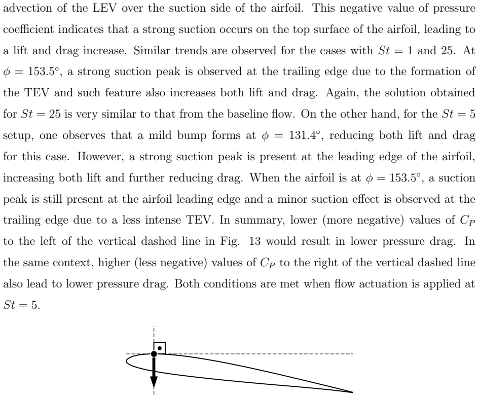
For a specific frequency range of actuation, mean drag and drag fluctuations are substantially reduced while mean lift is maintained almost unaffected, especially for a 2D actuator setup. For this frequency range, 2D flow actuation disrupts the formation of the dynamic stall vortex, what leads to drag reduction due to a pressure increase along the airfoil suction side, towards the trailing edge region. At the same time, pressure is reduced on the suction side near the leading edge, increasing lift and further reducing drag.
What carries the argument
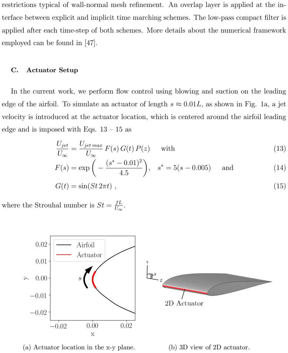
Spanwise-uniform 2D blowing-and-suction actuators at the leading edge that prevent dynamic stall vortex formation.
If this is right
- Mean drag drops substantially and its fluctuations are suppressed for the identified actuation frequencies.
- Mean lift coefficient remains nearly the same as the uncontrolled plunging case.
- The 2D actuator arrangement outperforms spanwise-varying 3D arrangements in drag reduction.
- Pressure recovery on the aft suction surface is the direct cause of the observed drag drop.
Where Pith is reading between the lines
- If the actuation power cost is low enough, the net energy budget for sustained operation could become favorable in periodic plunging devices.
- The same leading-edge placement and frequency scaling might transfer to other unsteady motions such as pitching or combined pitch-plunge.
- Because the benefit is tied to vortex disruption rather than direct momentum injection, the approach may remain effective at modestly higher Reynolds numbers where the stall vortex still dominates.
Load-bearing premise
The high-order finite-difference solver on a staggered grid accurately reproduces the three-dimensional vortex dynamics and surface pressures under active control at this Reynolds number.
What would settle it
Wind-tunnel measurements of time-averaged drag coefficient on the same plunging airfoil with matching leading-edge blowing and suction at the reported frequencies that show no net drag reduction relative to the uncontrolled case.
Figures


read the original abstract
High-fidelity simulations are performed to study active flow control techniques for alleviating deep dynamic stall of a SD7003 airfoil in plunging motion. The flow Reynolds number is $Re=60{,}000$ and the freestream Mach number is $M=0.1$. Numerical simulations are performed with a finite difference based solver that incorporates high-order compact schemes for differentiation, interpolation and filtering on a staggered grid. A mesh convergence study is conducted and results show good agreement with available data in terms of aerodynamic coefficients. Different spanwise arrangements of actuators are implemented to simulate blowing and suction at the airfoil leading edge. We observe that, for a specific frequency range of actuation, mean drag and drag fluctuations are substantially reduced while mean lift is maintained almost unaffected, especially for a 2D actuator setup. For this frequency range, 2D flow actuation disrupts the formation of the dynamic stall vortex, what leads to drag reduction due to a pressure increase along the airfoil suction side, towards the trailing edge region. At the same time, pressure is reduced on the suction side near the leading edge, increasing lift and further reducing drag.
Editorial analysis
A structured set of objections, weighed in public.
Referee Report
Summary. The manuscript reports high-fidelity simulations of active flow control on a plunging SD7003 airfoil at Re=60,000 and M=0.1 using a high-order compact finite-difference solver on a staggered grid. Different spanwise arrangements of leading-edge blowing/suction actuators are tested; for a specific frequency range, especially with 2D actuation, mean drag and drag fluctuations decrease substantially while mean lift is nearly unaffected. The mechanism is identified as disruption of the dynamic stall vortex, producing a suction-side pressure rise toward the trailing edge and a pressure drop near the leading edge.
Significance. If the controlled-flow results hold, the work demonstrates a targeted active-control strategy that achieves drag reduction in deep dynamic stall without lift penalty. Mesh convergence and baseline coefficient agreement with prior data provide a credible foundation for the uncontrolled case and credit the numerical setup; the actuated results would extend this to practical flow-control applications in unsteady aerodynamics if the vortex-disruption mechanism is confirmed.
major comments (3)
- [Abstract] Abstract and results: the reported drag reduction and pressure changes for actuated cases are presented without error bars, ensemble statistics, or quantitative uncertainty estimates, in contrast to the mesh-convergence study performed for the baseline; this directly affects in the quantitative magnitude of the claimed reductions for the 2D actuator configuration.
- [Numerical method] Numerical method and validation sections: mesh convergence and agreement with available data are shown only for the uncontrolled plunging case; no controlled-experiment comparison or actuator-specific sensitivity study is referenced for the 2D leading-edge blowing/suction, leaving the capture of 3D vortex disruption and resulting pressure integrals unvalidated at Re=60,000.
- [Results] Mechanism discussion: the central claim that 2D actuation disrupts dynamic-stall vortex formation (leading to the reported suction-side pressure rise toward the trailing edge) rests on the compact-scheme solver accurately resolving spanwise structures under 2D actuation; without additional resolution or boundary-condition checks for the actuated cases, this mechanism remains a potential numerical artifact.
minor comments (1)
- [Abstract] The abstract refers to 'a specific frequency range' without stating the nondimensional values or the corresponding Strouhal numbers; adding these would improve reproducibility.
Simulated Author's Rebuttal
We thank the referee for the constructive comments on our manuscript. We address each major comment point by point below, indicating planned revisions where appropriate.
read point-by-point responses
-
Referee: [Abstract] Abstract and results: the reported drag reduction and pressure changes for actuated cases are presented without error bars, ensemble statistics, or quantitative uncertainty estimates, in contrast to the mesh-convergence study performed for the baseline; this directly affects in the quantitative magnitude of the claimed reductions for the 2D actuator configuration.
Authors: The reported results are from deterministic high-fidelity simulations, with coefficients obtained by time-averaging over multiple plunging periods after initial transients have decayed. While explicit ensemble statistics or error bars were not included for the actuated cases, the drag reductions are consistent across the tested frequency band and actuator setups. We will revise the manuscript to include a quantitative discussion of cycle-to-cycle variations and the statistical convergence of the time averages for the actuated configurations. revision: partial
-
Referee: [Numerical method] Numerical method and validation sections: mesh convergence and agreement with available data are shown only for the uncontrolled plunging case; no controlled-experiment comparison or actuator-specific sensitivity study is referenced for the 2D leading-edge blowing/suction, leaving the capture of 3D vortex disruption and resulting pressure integrals unvalidated at Re=60,000.
Authors: Mesh convergence and validation against available data are presented for the baseline plunging case using the same numerical method and grids employed for all actuated simulations. The 2D leading-edge actuation is imposed via a time-dependent boundary condition on the existing mesh. No experimental data are available for the controlled SD7003 plunging case at this Reynolds number. We will add an actuator-specific grid-sensitivity study for the 2D configuration to the revised manuscript. revision: yes
-
Referee: [Results] Mechanism discussion: the central claim that 2D actuation disrupts dynamic-stall vortex formation (leading to the reported suction-side pressure rise toward the trailing edge) rests on the compact-scheme solver accurately resolving spanwise structures under 2D actuation; without additional resolution or boundary-condition checks for the actuated cases, this mechanism remains a potential numerical artifact.
Authors: The mechanism is supported by instantaneous and phase-averaged flow-field visualizations showing clear suppression of the dynamic-stall vortex under 2D actuation, together with the corresponding surface-pressure distributions. The high-order compact scheme and staggered-grid discretization have been validated on the baseline unsteady flow, and the 3D domain permits spanwise structures even when actuation is spanwise uniform. We will include an additional resolution and domain-size sensitivity check for the actuated 2D case in the revision. revision: yes
- Absence of experimental data for the actively controlled plunging airfoil at Re=60,000, which precludes direct experimental validation of the actuated results.
Circularity Check
No circularity: results are direct numerical outputs from NS solver
full rationale
The paper reports aerodynamic coefficients and flow structures obtained by solving the compressible Navier-Stokes equations with a high-order compact finite-difference scheme on a staggered grid. A mesh-convergence study and comparison to existing (uncontrolled) data are stated, but no analytical derivation, fitted parameter, or self-referential equation is present. The central observations (drag reduction via disruption of the dynamic-stall vortex under 2D actuation) are computed quantities, not quantities that reduce to the input data or to a prior self-citation by construction. No load-bearing self-citation, ansatz smuggling, or renaming of known results occurs.
Axiom & Free-Parameter Ledger
axioms (2)
- domain assumption The finite-difference solver with high-order compact schemes on a staggered grid resolves the relevant vortical structures at Re=60,000 and M=0.1
- domain assumption The SD7003 airfoil geometry and prescribed plunging kinematics are representative of the target unsteady flow regime
Reference graph
Works this paper leans on
-
[1]
W. J. McCroskey, Unsteady airfoils, Annual Review of Fluid Mechanics 14, 285 (1982)
work page 1982
-
[2]
Carr, Progress in analysis and prediction of dynamic stall, Journal of Aircraft 25, 6 (1988)
L. Carr, Progress in analysis and prediction of dynamic stall, Journal of Aircraft 25, 6 (1988)
work page 1988
-
[3]
J. Ekaterinaris and M. Platzer, Computational prediction of airfoil dynamic stall, Progress in Aerospace Sciences 33, 759–846 (1998)
work page 1998
-
[4]
T. C. Corke and F. O. Thomas, Dynamic stall in pitching airfoils: Aerodynamic damping and compressibility effects, Annual Review of Fluid Mechanics 47, 479–505 (2015)
work page 2015
-
[5]
J. Eldredge and A. Jones, Leading-edge vortices: Mechanics and modeling, Annual Review of Fluid Mechanics 51, 75–104 (2019)
work page 2019
-
[6]
N. D. Ham and M. I. Young, Limit cycle torsional motion of helicopter blades due to stall, Journal of Sound and Vibration 4, 431–432 (1966)
work page 1966
-
[7]
M. R. Visbal and J. S. Shang, Investigation of the flow structure around a rapidly pitching airfoil, AIAA Journal 27, 1044–1051 (1989)
work page 1989
-
[8]
M. R. Visbal, On the formation and control of the dynamic stall vortex on a pitching airfoil, in AIAA Paper 1991-6 (1991). 30
work page 1991
-
[9]
P. G. Choudhuri, D. D. Knight, and M. R. Visbal, Two-dimensional unsteady leading-edge separation on a pitching airfoil, AIAA Journal 32, 673–681 (1994)
work page 1994
-
[10]
M. R. Visbal, Dynamic stall of a constant-rate pitching airfoil, Journal of Aircraft 27, 400–407 (1990)
work page 1990
-
[11]
R. R., J. Windte, and S. U., Numerical and experimental flow analysis of moving airfoils with laminar separation bubbles, AIAA Journal 45, 1346–1356 (2007)
work page 2007
-
[12]
M. R. Visbal, Numerical investigation of deep dynamic stall of a plunging airfoil, AIAA Journal 49, 2152–2170 (2011)
work page 2011
-
[13]
M. R. Visbal, Numerical exploration of flow control for delay of dynamic stall on a pitching airfoil, in AIAA Paper 2014-2044 (2014)
work page 2014
-
[14]
M. R. Visbal, Control of dynamic stall on a pitching airfoil using high-frequency actuation, in AIAA Paper 2015-1267 (2015)
work page 2015
-
[15]
M. R. Visbal and D. J. Garmann, Control of dynamic stall over a pitching finite-aspect-ratio wing, in AIAA Paper 2017-4118 (2017)
work page 2017
-
[16]
S. I. Benton and M. R. Visbal, Evaluation of thermoacoustic-based forcing for control of dynamic stall, in AIAA Paper 2018-3683 (2018)
work page 2018
-
[17]
M. Visbal and S. Benton, Exploration of high-frequency control of dynamic stall using large- eddy simulations, AIAA Journal 56, 2974–2991 (2018)
work page 2018
-
[18]
McCroskey, The phenomenon of dynamic stall, National Aeronautics and Space Adminis- tration (1981)
W. McCroskey, The phenomenon of dynamic stall, National Aeronautics and Space Adminis- tration (1981)
work page 1981
-
[19]
C.-K. Kang, Y. S. Baik, Bernal, L. P., M. V., and W. Shyy, Fluid dynamics of pitching and plunging airfoils for Reynolds number between 1 x 10 4 and 6 x 10 4, in AIAA Paper 2009-536 (2009)
work page 2009
-
[20]
Y. S. Baik, J. M. Rausch, L. P. Bernal, and Ol., Experimental investigation of pitching and plunging airfoils at Reynolds number between 1 x 10 4 and 6 x 10 4, in AIAA Paper 2009-4030 (2009)
work page 2009
-
[21]
V. M. Ol, L. P. Bernal, C.-K. Kang, and W. Shyy, Shallow and deep dynamic stall for flapping low Reynolds number airfoils, Experiments in Fluids 46, 883–901 (2009)
work page 2009
- [22]
-
[23]
D. Greenblatt and I. Wygnanski, Dynamic stall control by periodic excitation, part 1: Naca 0015 parametric study, Journal of Aircraft 38, 430–438 (2001)
work page 2001
- [24]
- [25]
-
[26]
T. C. Corke, P. O. Bowles, C. He, and E. H. Matlis, Sensing and control of flow separation using plasma actuators, Philosophical Transactions of the Royal Society A: Mathematical, Physical and Engineering Sciences 369, 1459–1475 (2011)
work page 2011
-
[27]
A. Lombardi, P. Bowles, and T. Corke, Closed-loop dynamic stall control using a plasma actuator, AIAA Journal 51, 1130–1141 (2013)
work page 2013
-
[28]
M. L. Post and T. C. Corke, Separation control using plasma actuators: Dynamic stall vortex control on oscillating airfoil, AIAA Journal 44, 3125–3135 (2006)
work page 2006
- [29]
- [30]
- [31]
-
[32]
J. Ekaterinaris, Numerical investigations of dynamic stall active control for incompressible and compressible flows, Journal of Aircraft 39, 71–78 (2002)
work page 2002
-
[33]
R. Florea and B. Wake, Parametric analysis of directed-synthetic jets for improved dynamic- stall performance, 41st Aerospace Sciences Meeting and Exhibit, Aerospace Sciences Meetings (2003)
work page 2003
-
[34]
L. Carr, M. Chandrasekhara, M. Wilder, and K. Noonan, Effect of compressibility on sup- pression of dynamic stall using a slotted airfoil, Journal of Aircraft 38, 296–309 (2001)
work page 2001
-
[35]
M. Chandrasekhara, M. Tung, and P. Martin, Aerodynamic flow control using a variable droop leading edge airfoil, AVT Specialists’ Meet. Enhanc. NATO Mil. Flight Perform., Pap. RTO-MP-AVT-111 (2004)
work page 2004
- [36]
- [37]
-
[38]
P. Gerontakos and T. Lee, Dynamic stall flow control via a trailing-edge flap, AIAA Journal 44, 469–480 (2006)
work page 2006
-
[39]
D. Greenblatt, I. J. Wygnanski, and C. L. Rumsey, Aerodynamic flow control, Encyclopedia of Aerospace Engineering (2010)
work page 2010
-
[40]
Z. U. A. Warsi, K. Devarayalu, and J. F. Thompson, Numerical solution of the Navier-Stokes equations for arbitrary blunt bodies in supersonic flows, Numerical Heat Transfer 1, 499–516 (1978)
work page 1978
-
[41]
S. Yamamoto and H. Daiguji, A numerical method for the transonic cascade flow problem, Computers and Fluids 19, 461–477 (2001)
work page 2001
-
[42]
P. Orlandi, A numerical method for direct simulation of turbulence in complex geometries, CTR Annual Research Briefs , 215–229 (1989)
work page 1989
-
[43]
Choi, Turbulent Drag Reduction: Studies of Feedback Control and Flow Over Riblets, Ph.D
H. Choi, Turbulent Drag Reduction: Studies of Feedback Control and Flow Over Riblets, Ph.D. thesis, Stanford University (1992)
work page 1992
-
[44]
Z. Yang and Voke, Large-eddy simulation of boundary-layer separation and transition at a change of surface curvature, Journal of Fluid Mechanics 439, 305–333 (2001)
work page 2001
-
[45]
Aris, Vectors, Tensors, and the Basic Equations of Fluid Mechanics (Dover Publications, 1989)
R. Aris, Vectors, Tensors, and the Basic Equations of Fluid Mechanics (Dover Publications, 1989)
work page 1989
-
[46]
S. K. Lele, Compact finite difference schemes with spectral-like resolution, Journal of Com- putational Physics 103, 16–42 (1992)
work page 1992
-
[47]
Nagarajan, Leading Edge Effects in Bypass Transition , Ph.D
S. Nagarajan, Leading Edge Effects in Bypass Transition , Ph.D. thesis, Stanford University (2004)
work page 2004
-
[48]
See supplemental material at [url to be inserted by publisher] for a movie showing spanwise- averaged vorticity contours at different phases of the plunging motion with and withour ac- tuation. ()
-
[49]
See supplemental material at [url to be inserted by publisher] for a movie showing contours of spanwise-averaged pressure coefficient with iso-contours of z-vorticity with and withour actuation. ()
- [50]
-
[51]
P. Munday and K. Taira, Effects of wall-normal and angular momentum injections in airfoil separation control, AIAA Journal 56, 1830–1842 (2018)
work page 2018
-
[52]
See supplemental material at [url to be inserted by publisher] for a movie showing iso-surfaces of q-criterion colored by pressure coefficient comparing 2d and 3d actuations. ()
-
[53]
See supplemental material at [url to be inserted by publisher] for a movie showing the impact of different types of actuation on pressure coefficient along the airfoil suction side. ()
-
[54]
See supplemental material at [url to be inserted by publisher] for a movie showing the impact of different types of actuation on friction coefficient along the airfoil suction side. (). 34
discussion (0)
Sign in with ORCID, Apple, or X to comment. Anyone can read and Pith papers without signing in.