REVIEW 4 major objections 6 minor 22 references
Adaptive Twisting Sliding Control for Integrated Attack UAV's Autopilot and Guidance
T0 review · 4 major / 6 minor · reviewed 2026-08-10 · deepseek-v4-flash
Pith's one-line read An adaptive twisting sliding-mode controller using a zero-effort-miss sliding surface claims better interception accuracy than conventional and non-adaptive twisting sliding-mode controllers for an integrated attack-UAV guidance and…
desk verdict Routine but honest extension of the authors' adaptive twisting SMC to an integrated UAV guidance/autopilot loop; simulation is promising but the stability proof is a sketch and the reported miss metric is the very approximation the controller targets. read the letter →
The pith
A machine-rendered reading of the paper's core claim, the machinery that carries it, and where it could break.
The reading
What carries the argument
The load-bearing object is the zero-effort miss distance $$Z_I = -V_r t_{go}^2 \dot{\$\lambda$} + a_{TN}\$tau_T^{2}$\psi + C_I\Phi_I(t_{go})\bar{x}_I$$ (Eq. 20), an estimate of the miss that would occur if no further control were applied; it is used directly as the sliding surface $\sigma = Z_I$ (Eq. 25). Twisting sliding-mode control is a second-order sliding-mode scheme that switches between two gain levels depending on the sign of $\sigma\dot{\sigma}$. The controller splits into an equivalent control $u_{eq}$ (Eq. 35), obtained by setting $\dot{\sigma}=0$, and a discontinuous twisting part $u_T$ (Eq. 36) whose gain $\beta$ adapts through Eq. (37). The Lyapunov argument in Section 3.2 with condition (41) is what ties the adaptation to convergence: when the disturbance bounds are known, the gain condition ensures $\dot{V}\le 0$, so the sliding surface is reached and the ZEM is driven down.
What would settle it
Run a simulation of the same engagement with the target acceleration command raised above the bound used in condition (41), for example 25g instead of 20g, while allowing the closing speed $V_r$ to vary; if the zero-effort miss distance from Eq. (20) no longer tracks the true miss distance or the terminal ZEM grows, the claimed interception guarantee is falsified.
Extended reading notes
Core claim
The paper's central claim is that an adaptive twisting sliding-mode controller (ATSMC), built on a sliding surface equal to the zero-effort miss distance of the integrated UAV-target system, achieves smaller terminal miss distance and smoother engagement trajectories than conventional sliding-mode control (SMC) and non-adaptive twisting sliding-mode control (TSMC). The authors derive a vertical-plane model that couples the UAV's lateral dynamics with the relative kinematics, reduce the system order by projecting the miss distance onto the zero-effort miss distance, and close the loop with a twisting controller whose gain adapts online. In the simulated 3000 m engagement, with 20% parametric uncertainty, nonlinear couplings, and a target executing abrupt square-wave acceleration maneuvers, the proposed design reaches the smallest zero-effort miss distance at the terminal phase. The paper concludes that the adaptive strategy enhances interception accuracy against strong disturbances, nonlinearity, uncertainties, and sudden changes in the target's trajectory and speed.
Load-bearing premise
The load-bearing premise is that the closing speed and final time stay constant and the line-of-sight deviation stays small, so the zero-effort-miss expression equals the true miss distance, and that the controller knows upper bounds on all disturbances and modeling errors.
Editorial extensions
If this is right
- In the tested 3000 m engagement, the adaptive twisting controller reaches a smaller terminal ZEM than conventional SMC and non-adaptive TSMC.
- The adaptive gain grows with target speed, meaning the controller automatically demands more control power when the target is harder to catch.
- Because the approach does not require data feeding, it remains usable in combat situations where learning-based guidance methods lack training data.
- The design provides a single integrated control law that replaces the separated autopilot and guidance loops, reducing the miss distance caused by their instantaneous relative-geometry coupling.
- The authors' stated future step is to extend the controller to cooperative swarm or formation tasks, which would carry the same integrated design to multi-UAV engagements.
Reading between the lines
- The paper's vertical-plane derivation suggests a direct three-dimensional extension: run one ZEM-based adaptive twisting channel per perpendicular plane and coordinate them through the LOS frame; the paper does not test this.
- Because the stability proof needs known upper bounds on disturbances and modeling errors, a practical next test is an online bound estimator; if the target's acceleration exceeds the assumed bound, condition (41) no longer guarantees convergence.
- The reported comparison is a single simulated scenario, so a Monte Carlo sweep over initial heading errors, target maneuver phases, and parameter draws would show whether the smaller ZEM is systematic or specific to the chosen engagement.
- Treating the adaptive gain itself as a diagnostic signal is another testable idea: the paper shows gain magnitude rising with target speed, so gain history could be used to infer target maneuver intensity during flight.
Signed reviews
Editorial analysis
A structured set of objections, weighed in public.
Referee Report
Summary. The manuscript proposes an adaptive twisting sliding-mode controller (ATSMC) for an integrated UAV autopilot and guidance system attacking a target in the vertical plane. A zero-effort-miss (ZEM) quantity is used as the sliding surface, an equivalent control is derived from a linearized engagement model with constant closing speed, and an adaptive twisting discontinuous term is added. The paper reports simulation comparisons with conventional SMC and twisting SMC, showing smaller terminal ZEM for the proposed scheme. A Lyapunov-based stability argument is sketched in Section 3.2.
Significance. If the technical gaps were repaired, the contribution would be moderate: it applies adaptive twisting sliding-mode control to integrated guidance and autopilot using a ZEM surface, with explicit controller parameters and comparative scenarios that are useful for reproducibility. The paper does not provide machine-checked proofs or code, and the stability argument is incomplete, but the simulation setup is described in enough detail to be re-implemented. The main value lies in the application and in the comparative evaluation, provided the reported performance metric is validated against true miss distance.
major comments (4)
- [Section 3.2, Eq. (40)] The expression for dV/dt in the sigma*sigma_dot <= 0 case is asserted rather than derived. Equation (40) introduces undefined symbols sigma_I, mu_I, and the bounds bar_Delta_{aTNc}, bar_Delta_{aTNtau}, bar_Delta_{aI}, and it does not follow from the available expression for sigma_dot in Eq. (34). In particular, the discontinuous control enters sigma_dot through the term Phi_I^{(1,6)}(tgo) u_D / tau_s, whose sign and magnitude are not reflected in the bound (41); hence the conclusion V_dot <= 0 is not established.
- [Section 3.2, Eqs. (37)-(41)] The proof requires |sigma|^rho > epsilon for 'sufficiently small' epsilon, but for rho > 0 and epsilon > 0 this inequality fails in any neighborhood of the sliding surface sigma = 0. When |sigma|^rho <= epsilon, the sign term in Eq. (37) changes and the second term in Eq. (40) becomes positive, so the proposed Lyapunov argument cannot certify convergence to sigma = 0. A boundedness or dead-zone analysis, or a modified adaptation law, is needed to handle the region |sigma|^rho <= epsilon.
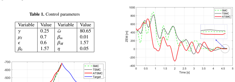
- [Sections 2.3-2.5 and Section 4, Fig. 6] The simulated 'Zero Effort Miss Distances' are computed from the approximate ZEM quantity ZI in Eq. (20), which rests on the constant Vr and t_f assumption in Section 2.3 and on the small-deviation approximation z approximately (lambda - lambda0) r in Eq. (18). The simulation, however, uses the full nonlinear kinematics of Eqs. (1)-(7) with a 20g square-wave target acceleration (Section 4.1), so Vr varies through Eq. (30) and the LOS deviation is not necessarily small. Thus the plotted quantity may be a biased proxy rather than the true miss distance; the claimed interception precision should be corroborated by the actual closest-approach distance or final relative displacement in the nonlinear simulation.
- [Section 2.5 and Eq. (34)] The notation Phi_I^{(1,6)}(tgo) is inconsistent: the text states it is a vector containing the first and sixth elements, while in Eq. (34) it multiplies delta_c / tau_s as a scalar. From Eq. (15), the correct coefficient is the (1,6) entry of the 6x6 state-transition matrix Phi_I(tgo) acting through the input vector B_I. Because this quantity enters the equivalent control (35) and the stability bound, the derivation must be corrected and the nonzero condition for this entry should be stated.
minor comments (6)
- [Section 3.2, Eq. (37)] The inequality 'epsilon >' is incomplete; it should read 'epsilon > 0', and the sign function should be defined at zero argument.
- [Section 3.2, after Eq. (40)] The phrase 'only the case alpha > alpha_M is considered here' uses alpha in place of the gain beta; this overloading with the angle of attack is confusing and should be corrected to beta > beta_m.
- [Section 2.5, Eq. (17)] The row vector notation C_I = [1 0 1x5] should be written explicitly as a 1x6 row vector, for example [1, 0, 0, 0, 0, 0].
- [Section 3.1, Eq. (35)] The equivalent control expression divides by Phi_I^{(1,6)}(tgo); the paper should state the condition under which this entry is nonzero and verify it in the simulated engagement.
- [Figure 5 caption] The word 'Cannar' is a typo and should be 'Canard'.
- [Section 3.2] The phrase 'one-stage accelerated convolutional algorithm condition' is unclear; it appears to be a typo, and the condition beta_i = max{beta*, gamma|sigma|^rho} should be explained more carefully.
Circularity Check
The reported ZEM metric is the controller's own sliding surface (Eq. 25 sets σ = ZI of Eq. 20), and the stability proof imports the authors' prior adaptive-twisting result [20]; the comparative simulation still retains independent content.
-
self definitional
[Sections 2.5, 3 (Eqs. 20, 25) and Section 4 (Fig. 6 discussion)]
"The ZEM in Eq. (20), which is desired to drive to zero, will be regarded as the sliding surface: σ = ZI, ... The simulation results for ZEM are presented in Fig. 6 ... Contrary to the SMC and TSMC, our proposed method exhibits a lesser overshoot in ZEM and the smallest value at the engagement phase."
By Eq. (25), the sliding surface is defined as the zero-effort miss: σ = ZI, with ZI from Eq. (20). The control law is then deliberately designed to drive σ to zero: ueq is obtained by setting σ̇ = 0 (Eq. 35) and uD is a twisting law on σ (Eq. 36). The paper's evidence of 'interception accuracy' is Fig. 6, which plots exactly this controlled quantity. Hence the demonstrated smallness of ZEM is, to first order, the controller achieving its own design objective: the performance metric equals the controlled variable by construction (Eq. 20 = Eq. 25). The true closest-approach distance of the nonlinear simulation (Eqs.
-
self citation load bearing
[Section 3.2, Eqs. (36)-(41)]
"we advocate for an adaptive adjustment of the gainβi in (36) following the innovative approach outlined in [20]. ... Motivated by [18, 21] and [20], Eq. (39) can be rewritten for the caseσ ˙σ≤ 0 as, ˙V =−|σI| (µI− ¯∆aT Nc− ¯∆aT Nτ− ¯∆aI) + ¯ω γµ (β−βM)sign(|σ|ρ−ϵ) (40)"
The load-bearing step for convergence is Eq. (40), which establishes ˙V ≤ 0 subject to condition (41). The paper does not derive (40) from the plant-specific σ̇ of Eq. (34); it asserts that, 'Motivated by [18, 21] and [20], Eq. (39) can be rewritten' as (40). Reference [20] and [16] are the same authors' prior adaptive-twisting works, and the adaptation law (37) is likewise introduced by citing [20]. The stability of the proposed ATSMC is therefore largely imported from the authors' own earlier result rather than re-derived for this integrated plant. Condition (41) also omits the state-dependent coefficient Φ_I^(1,6)/τ_s that multiplies the discontinuous control in Eq. (34).
full rationale
The core derivation chain — relative kinematics (Eqs. 1-7), the integrated linear model (Eq. 15), the ZEM expression (Eq. 20), and the equivalent control (Eq. 35) — is derived inline with support from external references [18], [19], [21], [22]; no parameter is fitted to the simulated target scenario and no known result is simply renamed. The two circularity-relevant features are: (1) the performance evidence (Fig. 6) plots ZI of Eq. (20), which by Eq. (25) is exactly the sliding variable the control law is designed to drive to zero, so the absolute claim of 'interception precision' reduces in part to the controller achieving its own objective, and the true miss distance of the nonlinear simulation is never reported; the comparative ATSMC-versus-SMC/TSMC ordering, however, is not forced by construction. (2) The adaptive gain law (37) and the key stability inequality (40) are imported from the authors' own prior work [16], [20]; Eq. (40) is asserted via citation rather than derived from the actual σ̇ in (34). Per the rules, the paper's own simulation is an externally falsifiable test of the imported adaptive scheme, so the self-citation is not fully load-bearing. Concerns that the 20g square-wave target violates the constant-Vr and small-LOS assumptions behind Eq. (20) are validity threats to the ZEM proxy, not circularity, and do not raise the score further. Overall the central claim retains independent content, keeping the score below 6.
Assumptions & free parameters
free parameters (6)
- γ (adaptive law gain) =
0.25
- ω̄ (adaptation rate) =
80.65
- µI (twisting ratio) =
0.7
- ϵ (adaptation threshold exponent) =
0.6
- βm, βM, β0 (gain bounds and initial value) =
0.01, 1.57, 1.57
- η (adaptation floor rate) =
0.05
assumptions (6)
- domain assumption The target has constant speed and a first-order lag for its acceleration dynamics (Eq. 6).
- domain assumption The UAV longitudinal dynamics are linearized with constant aerodynamic coefficients, ignoring thrust and speed changes (Eqs. 7, 12).
- ad hoc to paper The closing speed Vr and final time t_f are constant (Section 2.3).
- ad hoc to paper The relative deviation perpendicular to the initial LOS is small, so z≈(λ−λ0)r (Section 2.5).
- domain assumption The disturbance and modeling-error bounds Δ̄aMN, Δ̄aTN, Δ̄I are known and bounded (Section 3.2).
- ad hoc to paper The adaptation condition |σ|^ρ > ϵ holds with sufficiently small ϵ (Section 3.2, citing [22]).
Cite this review
Pith. "Pith review of Adaptive Twisting Sliding Control for Integrated Attack UAV's Autopilot and Guidance." pith.science (2026). https://pith.science/paper/FUCDOBZQ
@misc{pith2026250109937,
  author       = {Pith},
  title        = {Pith review of: Adaptive Twisting Sliding Control for Integrated Attack UAV's Autopilot and Guidance},
  year         = {2026},
  howpublished = {\url{https://pith.science/paper/FUCDOBZQ}},
  note         = {Machine review of arXiv:2501.09937}
}
read the original abstract
This paper investigates an adaptive sliding-mode control for an integrated UAV autopilot and guidance system. First, a two-dimensional mathematical model of the system is derived by considering the incorporated lateral dynamics and relative kinematics of the UAV and its potential target of attack. Then, a sliding surface is derived utilizing the zero-effort miss distance. An adaptive twisting sliding mode (ATSMC) algorithm is applied to the integrated system. Simulation and comparisons have been accomplished. The results show our proposed design performs well in interception precision, even with high nonlinearity, uncertainties, disturbances, and abrupt changes in the target's movement, thanks to the adaptation strategy.
Figures


Figures from the paper (2 more)

Reference graph
Works this paper leans on
-
[20]
V .T. Hoang, M.D. Phung, Q.P. Ha, Adaptive twist- ing sliding mode control for quadrotor unmanned aerial vehicles, in 2017 11th Asian Control Confer- ence (ASCC) (2017), pp. 671–676
work page 2017
- [21]
-
[18]
A. Zhurbal, M. Idan, E ffect of estimation on the per- formance of an integrated missile guidance and con- trol system, IEEE Transactions on Aerospace and Electronic systems 47, 2690 (2011)
work page 2011
-
[1]
F. Santoso, M.A. Garratt, S.G. Anavatti, State-of-the- art integrated guidance and control systems in un- manned vehicles: A review, IEEE Systems Journal 15, 3312 (2020)
work page 2020
-
[2]
T. Chao, D. Zhang, S. Wang, P. Ma, Integrated guid- ance and control design considering system uncer- tainty, Proceedings of the Institution of Mechanical Engineers, Part G: Journal of Aerospace Engineering 233, 2278 (2019)
work page 2019
-
[3]
Y . Shen, M. Chen, M. Lungu, H. Guo, Decoupled finite-time approximation auxiliary system-based three-dimensional integrated guidance and control, IEEE Transactions on Automation Science and En- gineering (2024)
work page 2024
-
[4]
B. Ma, Z. Liu, Q. Dang, W. Zhao, J. Wang, Y . Cheng, Z. Yuan, Deep reinforcement learning of uav track- ing control under wind disturbances environments, IEEE Transactions on Instrumentation and Measure- ment 72, 1 (2023)
work page 2023
-
[5]
J. Moon, S. Papaioannou, C. Laoudias, P. Ko- lios, S. Kim, Deep reinforcement learning multi- uav trajectory control for target tracking, IEEE Internet of Things Journal 8, 15441 (2021). 10.1109/JIOT.2021.3073973
arXiv 2021
Show all 22 references
-
[6]
Y . Yuan, J. Yang, Z.L. Yu, Y . Cheng, P. Jiao, L. Hua, Hierarchical goal-guided learning for the evasive ma- neuver of fixed-wing uavs based on deep reinforce- ment learning, Journal of Intelligent & Robotic Sys- tems 109, 43 (2023)
2023
-
[7]
Cross, Y .B
M.A. Cross, Y .B. Shtessel, Single-loop integrated guidance and control using high-order sliding-mode control, Variable-Structure Systems and Sliding- Mode Control: From Theory to Practice pp. 433–462 (2020)
2020
-
[8]
S. Yang, J. Guo, J. Zhou, New integrated guidance and control of homing missiles with an impact an- gle against a ground target, International Journal of Aerospace Engineering 2018, 3968242 (2018)
2018
-
[9]
S.U. Ali, R. Samar, M.Z. Shah, A.I. Bhatti, K. Mu- nawar, U.M. Al-Sggaf, Lateral guidance and control of uavs using second-order sliding modes, Aerospace Science and Technology 49, 88 (2016)
2016
-
[10]
Levant, Sliding order and sliding accuracy in slid- ing mode control, International journal of control58, 1247 (1993)
A. Levant, Sliding order and sliding accuracy in slid- ing mode control, International journal of control58, 1247 (1993)
1993
-
[11]
twisting
A. Polyakov, A. Poznyak, Lyapunov function design for finite-time convergence analysis:“twisting” con- troller for second-order sliding mode realization, Au- tomatica 45, 444 (2009)
2009
-
[12]
super-twisting
A. Polyakov, A. Poznyak, Reaching time estimation for “super-twisting” second order sliding mode con- troller via lyapunov function designing, IEEE Trans- actions on Automatic Control 54, 1951 (2009)
2009
-
[13]
Shtessel, M
Y . Shtessel, M. Taleb, F. Plestan, A novel adaptive- gain supertwisting sliding mode controller: method- ology and application, Automatica 48, 759 (2012)
2012
-
[14]
Y . Dvir, A. Levant, Accelerated twisting algorithm, IEEE Transactions on Automatic Control 60, 2803 (2015)
2015
-
[15]
Zheng, J.J
E.H. Zheng, J.J. Xiong, J.L. Luo, Second order slid- ing mode control for a quadrotor uav, ISA transac- tions 53, 1350 (2014)
2014
-
[16]
Hoang, A.M
V .T. Hoang, A.M. Singh, M.D. Phung, Q.P. Ha, Adaptive Second-order Sliding Mode Control of UA Vs for Civil Applications, in Automation and Robotics in Construction (ISARC), 2017 Interna- tional Symposium on (2017), pp. 816–822
2017
-
[17]
Phung, T.H
M.D. Phung, T.H. Dinh, Q.P. Ha et al., System archi- tecture for real-time surface inspection using multi- ple uavs, IEEE Systems Journal 14, 2925 (2019)
2019
-
[19]
Shaferman, T
V . Shaferman, T. Shima, Cooperative optimal guid- ance laws for imposing a relative intercept angle, Journal of Guidance, Control, and Dynamics 38, 1395 (2015)
2015
-
[22]
Kumar, D
S.R. Kumar, D. Ghose, Impact time guidance for large heading errors using sliding mode control, IEEE Transactions on Aerospace and Electronic Sys- tems 51, 3123 (2015)
2015
Reviewed August 10, 2026 · model on record in the stance chip above.
Discussion (0). Continue with ORCID to comment.