REVIEW 3 major objections 5 minor 2 cited by
Ultra-wideband Double-Directionally Resolved Channel Measurements of Line-of-Sight Microcellular Scenarios in the Upper Mid-band
T0 review · 3 major / 5 minor · reviewed 2026-08-11 · deepseek-v4-flash
Pith's one-line read First double-directional UWB channel maps of the 6–18 GHz upper mid-band show street-canyon multipath pulling path loss below free space.
desk verdict First real double-directional UWB dataset in 6–18 GHz, worth refereeing, but the 'omni' PDP is a max-hold beam-selection metric, not a power sum—so the fitted omni path-loss parameters are not directly portable, even though the below-free-space result is conservative. read the letter →
The pith
A machine-rendered reading of the paper's core claim, the machinery that carries it, and where it could break.
The reading
What carries the argument
The machinery is a double-directional ultra-wideband channel sounder: a VNA that records the complex transfer function over 6–18 GHz in 12,001 frequency points, front-ended by high-gain horn antennas on precision positioners, so every link is resolved in Tx azimuth, Rx azimuth, and Rx elevation. A time-gated over-the-air calibration isolates system and antenna effects from the channel response. From the calibrated transfer functions the paper forms directional power delay profiles by inverse Fourier transform, picks the strongest beam pair (Max-Dir) by total power, and builds an 'omni' PDP by summing over the five Rx co-elevations while selecting the strongest Tx and Rx azimuth per delay bin. Path loss, RMS delay spread, and the angular-spread metric are then fitted with power-law and Gaussian models per 1 GHz sub-band.
What would settle it
Rebuild the omni PDP by summing received power over all measured azimuth and elevation directions at each delay bin instead of selecting the strongest azimuth, then recompute path gain and path loss; if the summed path loss rises to or above the free-space curve, the below-free-space result depends on the max-hold processing rather than on true omnidirectional reception. A complementary check would be a control measurement in an open field with no building reflections.
Extended reading notes
Core claim
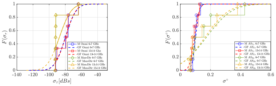
In a line-of-sight microcellular street-canyon scenario, over the 6–18 GHz upper mid-band, the paper reports the first double-directional ultra-wideband measurement campaign, built from more than 14,000 directional power delay profiles collected with a 12 GHz-bandwidth RF-over-fiber VNA sounder and horn antennas rotated in azimuth and elevation at both link ends. It finds that path loss for both the best-beam (Max-Dir) and the constructed omni-directional power delay profile is below the free-space value, which the authors attribute to multipath contributions from buildings on both sides of the street; the only exception is a receiver partially obstructed by tree branches, which shows loss above free space. Path loss still rises with distance and frequency, but remains below the free-space curve over the observed range. It further finds that RMS delay spread and angular spread at the transmitter and receiver are nearly the same across every 1 GHz sub-band as across the full band, indicating that the channel's time and angular dispersion are stable over this frequency range.
Load-bearing premise
The below-free-space path loss result rests on defining the 'omni-directional' profile by selecting, at each delay, the strongest azimuth direction rather than adding power from all directions; that max-hold choice can only raise collected power, so the conclusion depends on this processing proxy rather than on a true omnidirectional antenna.
Editorial extensions
If this is right
- LoS microcellular links in street canyons can expect path loss below the free-space value across 6–18 GHz, so free-space-based link budgets are conservative for these deployments.
- Best-beam reception spatially filters late reflections, so beamformed links see lower RMS delay spread than the omni profile; the delay-spread gap between Max-Dir and omni is a direct consequence of this filtering.
- Delay spread and angular spread statistics change little across 1 GHz sub-bands, meaning one set of model parameters could serve the whole 6–18 GHz range for LoS microcells.
- Fitted shadowing standard deviations are small, mostly under 3 dB, so LoS coverage predictions can use a tight lognormal margin.
- The one tree-obstructed receiver shows loss above free space, indicating vegetation can reverse the multipath gain and deserves separate treatment in FR3 models.
Reading between the lines
- Editorial inference: re-summing power over all measured azimuth directions at each delay bin, instead of taking the strongest one, would lower the constructed omni path gain; the below-free-space omni path loss may shrink or disappear under true power summation.
- Editorial inference: with only six receiver points spanning 59–185 m, the distance dependence of delay and angular spread is weakly constrained; the paper's own linear fits have confidence intervals straddling zero, so the stability claim is better supported across frequency than across distance.
- Editorial inference: the same double-directional dataset could be reprocessed to extract per-cluster angles and delays for ray-tracing validation at FR3, or to test whether a single stochastic cluster model holds across the 12 GHz bandwidth.
Editorial analysis
A structured set of objections, weighed in public.
Referee Report
Summary. This paper describes a 6-18 GHz double-directional channel sounding campaign in an urban LoS microcellular street canyon. The authors sweep Tx/Rx azimuth and Rx elevation angles, construct directional PDPs, combine them into 'omni' and 'best-beam' PDPs, and fit path-loss, shadowing, delay-spread, and angular-spread statistics for the full band and for 1-GHz sub-bands. The headline claims are that this is the first double-directional UWB measurement campaign in the upper mid-band; that both omni and best-beam path loss fall below the Friis free-space prediction due to multipath; and that delay spread and angular spread are stable across the 1-GHz sub-bands.
Significance. If the data and processing are reliable, the campaign provides a scarce resource: double-directional ultra-wideband measurements in the 6-18 GHz FR3 candidate band, with enough bandwidth to study sub-band dependence. The visual validation of identified MPCs against the RTH and GER building reflections and the LoS distance in Figs. 2-3 is credible and gives confidence in the angular association and the measured delays. The paper is also honest that all model parameters are fits to the measured data and does not present derivation-based predictions. However, the 'omni' quantity defined in Eq. (5) is not a true omnidirectional response, so the fitted 'omni' path-loss parameters in Table III are not directly portable to system analysis. This is the main load-bearing issue and it can be addressed by recomputing the omni PDP as a power sum over directions.
major comments (3)
- [III, Eq. (5)] The 'omni-directional' PDP is defined by taking, for each delay bin, the maximum over Tx/Rx azimuth pairs after summing the five Rx co-elevations, rather than by summing power over all directions. Since a maximum is no larger than the corresponding sum, P_omni(tau) is a lower bound on a true omni-directional PDP, and the resulting path gain is a lower bound on the true omni path gain; the stress-test concern therefore lands, but the direction is the opposite of the reader's phrasing of an upward bias. The substantive problem stands: the fitted alpha, beta, and sigma in Table III and Fig. 4a describe a per-delay best-beam-selection metric, not an omnidirectional antenna, and they depend on the 10-degree angular grid, the horn beamwidth, the thresholding in Eq. (3), and the fact that the Tx scans only a 120-degree sector. Please recompute P_omni as a power sum over all measured directions with the same reference-gain normalization as Eq. (1), or relabel the metric and restrict all 'omni' claims accordingly. The qualitative below-free-space claim would become stronger, not weaker, under a true power-sum omni PDP, so that part of the abstract may survive the correction; however, the numerical model in Table III is not an omni model.
- [II-A and III, Eq. (1)] The absolute path-loss comparison in Fig. 4 and the fitted alpha/beta values require an explicit definition of path gain and of how the horn antenna gains and the OTA reference are removed. The manuscript only states that the parameters are defined in prior work [21], [22]. Without the formula linking the calibrated transfer function of Eq. (1) to PG and PL, and without stating the reference-gain basis of the Friis comparison, the reader cannot verify that the reported path loss is on an isotropic-gain basis. Please include the explicit path-gain/path-loss definition and the calibration normalization used in Fig. 4 and Tables III-V.
- [IV-D, Table VII] The 'All Bands' row of Table VII reports mu = -97.14 dB s and sigma = 2.40 dB s, while every 1-GHz sub-band row reports mu near -87.3 dB s and sigma near 11.7 dB s. Pooling the sub-band samples should not shift the mean by 10 dB or shrink the standard deviation by roughly a factor of five; this entry appears erroneous. The full-band statistics feed the stability claim in the abstract and conclusions, so this entry should be corrected or the discrepancy explained.
minor comments (5)
- [III, Eq. (3)] The expression [P_calc(tau) : (tau <= tau_gate) AND (P_calc(tau) >= P_lambda)] does not specify what happens to samples that fail the conditions; please state explicitly that they are discarded or set to zero.
- [III, Eq. (4)] In Eq. (4), 'arg max' returns the indices of the maximizing beam pair, but the left-hand side is a function of delay; please write P_Max-Dir(tau) as the value of P at the maximizing indices.
- [IV-C] There is a typo in the paragraph on Rx6: 'partial obstruction pf the LoS' should read 'partial obstruction of the LoS'; similarly, in Section IV-B, 'attenuated it is partially hitting' is ungrammatical and should be rephrased.
- [Tables III-IV] Because the path-loss fits use only six Rx locations, the 95% confidence intervals are very broad; the text acknowledges this, but the table captions should state the number of locations so that readers do not over-interpret the fitted exponents.
- [IV-E] The statement that the lower bound of the measured angular spread follows from the beamwidth of the directional antenna should be quantified, since the 10-degree angular grid also imposes a discretization limit on the resolvable angular spread.
Circularity Check
No significant circularity: all reported quantities are explicit fits to the measured data, self-citations only support the measurement methodology, and the Eq. (5) max-hold 'omni' PDP issue is a validity concern rather than a circular reduction.
full rationale
This paper is a measurement-reporting paper, not a derivation or prediction paper. The path-loss parameters (alpha, beta) and shadowing sigma in Tables III-V are explicitly labeled as linear/Gaussian fits to the measured path gains, and the delay-spread and angular-spread statistics in Tables VI-IX are fits to measured CDFs; no quantity is claimed to be predicted from first principles or from a fitted parameter renamed as a prediction. The comparison to free-space (Friis) values is a benchmark applied after fitting, not an input to the fitting. The self-citations [21]-[23] are cited only for the sounder architecture, thresholding/delay-gating, and the impact of noise threshold selection, and [24] is cited for the max-hold construction of P_omni; these citations support the processing methodology but do not carry the physical conclusions about path loss or spread stability. The one substantive concern, Eq. (5), defines P_omni by taking the maximum over azimuth directions per delay bin rather than summing incident power over all directions; this affects whether the reported 'omni-directional' path loss is actually the property of a true omnidirectional antenna. However, this is a measurement-validity and labeling issue, not a circularity: no equation in the paper is equivalent to its own input by construction, and no fitted parameter is presented as an independent prediction. The manuscript also candidly notes broad 95% confidence intervals and the tree-obstruction deviation at Rx6, which further supports that the results are reported as observations rather than as forced conclusions. Overall, the derivation chain, such as it is, is self-contained empirical reporting, and no circular step can be exhibited.
Assumptions & free parameters
free parameters (3)
- Path loss intercept and exponent (Omni and Max-Dir, per band) =
alpha from 41.82 to 73.42 dB (Omni), beta from 0.76 to 1.97 (Omni); see Tables III and IV
- Shadowing standard deviation (Omni and Max-Dir) =
1.37 dB (All Bands Omni), 1.66 dB (All Bands Max-Dir); per-band values in Table V
- Gaussian CDF parameters for RMSDS and AS =
e.g., RMSDS Omni mu=-83.53 dB s (All Bands), AS_Rx mu=0.18 (All Bands); full values in Tables VI-IX
assumptions (4)
- domain assumption The OTA calibration at 44 m removes system and antenna effects and yields an absolute path gain scale suitable for comparing to free-space.
- domain assumption The max-hold 'omni' PDP in Eq. (5) is an adequate proxy for an omnidirectional receiver for the purpose of path loss comparison.
- domain assumption The environment remains static during each several-hour double-directional measurement.
- standard math IFFT-based PDP and Fleury's angular spread definitions are standard and valid.
Cite this review
Pith. "Pith review of Ultra-wideband Double-Directionally Resolved Channel Measurements of Line-of-Sight Microcellular Scenarios in the Upper Mid-band." pith.science (2026). https://pith.science/paper/WZV5UBDG
@misc{pith2026241212306,
  author       = {Pith},
  title        = {Pith review of: Ultra-wideband Double-Directionally Resolved Channel Measurements of Line-of-Sight Microcellular Scenarios in the Upper Mid-band},
  year         = {2026},
  howpublished = {\url{https://pith.science/paper/WZV5UBDG}},
  note         = {Machine review of arXiv:2412.12306}
}
read the original abstract
The growing demand for higher data rates and expanded bandwidth is driving the exploration of new frequency ranges, including the upper mid-band spectrum (6-24 GHz), which is a promising candidate for future Frequency Range 3 (FR3) applications. This paper presents ultra-wideband double-directional channel measurements in line-of-sight microcellular scenarios within the upper mid-band spectrum (6-18 GHz). Conducted in an urban street canyon environment, these measurements explore key channel characteristics such as power delay profiles, angular power spectra, path loss, delay spread, and angular spread to provide insights essential for robust communication system design. Our results reveal that path loss values for both omni-directional and best beam configurations are lower than free-space predictions due to multipath contributions from the environment. Analysis also indicates a high degree of stability in delay spread and angular spread across the entire band, with small variation between sub-bands.
Figures


Figures from the paper (1 more)
Forward citations
Cited by 2 Pith papers
-
Ultra-Wideband Double-Directional Channel Measurements and Statistical Modeling in Urban Microcellular Environments for the Upper-Midband/FR3
An 8 GHz-bandwidth double-directional channel measurement campaign in an urban microcell at 6-14 GHz produces statistical models for path loss, delay spread, and angular spread, and highlights vegetation-obstructed Lo...
-
An Ultra-Wideband Study of Vegetation Impact on Upper Midband / FR3 Communication
Urban measurements at 6-18 GHz show excess vegetation loss of about 1.26-1.79 dB per meter of tree depth, increasing with frequency.
Reference graph
Works this paper leans on
-
[21]
Thz band cha nnel measurements and statistical modeling for urban d2d enviro nments,
N. A. Abbasi, J. L. Gomez, R. Kondaveti, S. M. Shaikbepar i, S. Rao, S. Abu-Surra, G. Xu, J. Zhang, and A. F. Molisch, “Thz band cha nnel measurements and statistical modeling for urban d2d enviro nments,” IEEE Transactions on Wireless Communications , vol. 22, no. 3, pp. 1466–1479, 2022
2022
-
[22]
Th z band channel measurements and statistical modeling for urban mi crocellular environments,
N. A. Abbasi, J. Gomez-Ponce, R. Kondaveti, A. Kumar, E. Bhagat, R. N. Rao, S. Abu-Surra, G. Xu, C. Zhang, and A. F. Molisch, “Th z band channel measurements and statistical modeling for urban mi crocellular environments,” IEEE Transactions on Wireless Communications , 2023
2023
-
[1]
C ellular wireless networks in the upper mid-band,
S. Kang, M. Mezzavilla, S. Rangan, A. Madanayake, S. B. V e nkatakrish- nan, G. Hellbourg, M. Ghosh, H. Rahmani, and A. Dhananjay, “C ellular wireless networks in the upper mid-band,” IEEE Open Journal of the Communications Society , 2024
work page 2024
-
[2]
Enabling 6g performance in the upper mid-band through gigantic mimo,
E. Björnson, F. Kara, N. Kolomvakis, A. Kosasih, P . Ramez ani, and M. B. Salman, “Enabling 6g performance in the upper mid-band through gigantic mimo,” arXiv preprint arXiv:2407.05630 , 2024
arXiv 2024
-
[3]
Rel-19 ran1 agreements - 7-24 ghz channel modelin g,
RAN 1, “Rel-19 ran1 agreements - 7-24 ghz channel modelin g,” 3GPP , Tech. Rep., 2025
2025
-
[4]
Ultra-wide-band propagation channels,
A. F. Molisch, “Ultra-wide-band propagation channels, ” Proceedings of the IEEE , vol. 97, no. 2, pp. 353–371, 2009
2009
-
[5]
D. Shakya, M. Ying, T. S. Rappaport, H. Poddar, P . Ma, Y . Wa ng, and I. Al-Wazani, “Wideband penetration loss through building materials and partitions at 6.75 ghz in fr1 (c) and 16.95 ghz in the fr3 upper mid-band spectrum,” arXiv preprint arXiv:2405.01362 , 2024
arXiv 2024
-
[6]
Diffraction measurements around a build ing corner at 10 ghz,
N. Tervo, C. F. Dias, V . Hovinen, M. Sonkki, A. Roivainen, J. Meinilä, and M. Latva-aho, “Diffraction measurements around a build ing corner at 10 ghz,” in 1st International Conference on 5G for Ubiquitous Connectivity. IEEE, 2014, pp. 187–191
2014
Show all 26 references
-
[7]
Wideband ind oor channel measurements and ber analysis of frequency selective multi path channels at 2.4, 4.75, and 11.5 ghz,
G. J. Janssen, P . A. Stigter, and R. Prasad, “Wideband ind oor channel measurements and ber analysis of frequency selective multi path channels at 2.4, 4.75, and 11.5 ghz,” IEEE Transactions on Communications , vol. 44, no. 10, pp. 1272–1288, 1996
1996
-
[8]
An empirical propagation pre diction model for urban street canyon environments at 6, 10, and 18 gh z,
S.-S. Oh, J.-W. Choi, H.-C. Lee, Y .-C. Lee, B.-L. Cho, I.- Y . Lee, J.-H. Lim, J.-I. Lee, and S. W. Park, “An empirical propagation pre diction model for urban street canyon environments at 6, 10, and 18 gh z,” Microwave and Optical Technology Letters , vol. 61, no. 6, pp. 15...
2019
-
[9]
Path loss characterizati on of 7-ghz terrestrial propagation channel in urban environment,
N. Y oza-Mitsuishi and R. Sun, “Path loss characterizati on of 7-ghz terrestrial propagation channel in urban environment,” in 2019 IEEE 90th V ehicular Technology Conference (VTC2019-Fall) . IEEE, 2019, pp. 1–5
2019
-
[10]
Radio channel pr opagation measurements using a multiband agile chirp sounder,
S. Salous, A. Cheema, and X. Raimundo, “Radio channel pr opagation measurements using a multiband agile chirp sounder,” in 2014 XXXIth URSI General Assembly and Scientific Symposium (URSI GASS) . IEEE, 2014, pp. 1–4
2014
-
[11]
Outdoo r wideband channel measurements and modeling in the 3–18 ghz band,
V . Kristem, C. U. Bas, R. Wang, and A. F. Molisch, “Outdoo r wideband channel measurements and modeling in the 3–18 ghz band,” IEEE Transactions on Wireless Communications , vol. 17, no. 7, pp. 4620– 4633, 2018
2018
-
[12]
Measured wideband characteristics of indoor channels at c entimetric and millimetric bands,
W. Fan, I. Carton, J. Ø. Nielsen, K. Olesen, and G. F. Pede rsen, “Measured wideband characteristics of indoor channels at c entimetric and millimetric bands,” EURASIP Journal on Wireless Communications and Networking , vol. 2016, pp. 1–13, 2016
2016
-
[13]
Spatio-temporal channel sounding in a street canyon at 15, 28 and 60 ghz,
R. Naderpour, J. V ehmas, S. Nguyen, J. Järveläinen, and K. Haneda, “Spatio-temporal channel sounding in a street canyon at 15, 28 and 60 ghz,” in 2016 IEEE 27th annual international symposium on personal, indoor , and mobile radio communications (PIMRC) . IEEE, 2016, pp. 1–6
2016
-
[14]
Comparison of par ametric and nonparametric characterization of 15 ghz propagation c hannels in indoor environments,
C. Ling, X. Yin, H. Wang, and X. Zhang, “Comparison of par ametric and nonparametric characterization of 15 ghz propagation c hannels in indoor environments,” in 2016 10th European Conference on Antennas and Propagation (EuCAP) . IEEE, 2016, pp. 1–5
2016
-
[15]
Propagation chann el character- ization for 6–14 ghz bands based on large array measurement f or indoor scenarios,
Q. Wang, X. Yin, J. Hong, and G. Jing, “Propagation chann el character- ization for 6–14 ghz bands based on large array measurement f or indoor scenarios,” Electronics, vol. 11, no. 22, p. 3675, 2022
2022
-
[16]
Sub- 6 ghz to mmwave for 5g-advanced and beyond: Channel measurem ents, characteristics and impact on system performance,
H. Miao, J. Zhang, P . Tang, L. Tian, X. Zhao, B. Guo, and G. Liu, “Sub- 6 ghz to mmwave for 5g-advanced and beyond: Channel measurem ents, characteristics and impact on system performance,” IEEE Journal on Selected Areas in Communications , vol. 41, no. 6, pp. 1945–1960, 2023
1945
-
[17]
Dense multipath com ponent characteristics in 11-ghz-band indoor environments,
K. Saito, J.-I. Takada, and M. Kim, “Dense multipath com ponent characteristics in 11-ghz-band indoor environments,” IEEE Transactions on Antennas and Propagation , vol. 65, no. 9, pp. 4780–4789, 2017
2017
-
[18]
Indoor and outdoor experiment s on 5g radio access using distributed mimo and beamforming in 15 ghz frequency band,
D. Kurita, K. Tateishi, A. Harada, Y . Kishiyama, S. Itoh , H. Murai, A. Simonsson, and P . Okvist, “Indoor and outdoor experiment s on 5g radio access using distributed mimo and beamforming in 15 ghz frequency band,” in 2016 IEEE Globecom W orkshops (GC Wkshps) . IEEE, 2016, pp. 1–6
2016
-
[19]
V a lidation of deterministic radio channel model by 10 ghz microcell measu rements,
A. Roivainen, P . Kyoesti, V . Hovinen, and C. F. Dias, “V a lidation of deterministic radio channel model by 10 ghz microcell measu rements,” in European Wireless 2016; 22th European Wireless Conference . VDE, 2016, pp. 1–6
2016
-
[20]
Urban outdoor propagation measurements and channel models at 6.75 ghz fr1 (c) and 16.95 ghz fr3 upper mid-band spectrum for 5g and 6g,
D. Shakya, M. Ying, T. S. Rappaport, P . Ma, I. Al-Wazani, Y . Wu, Y . Wang, D. Calin, H. Poddar, A. Bazzi et al. , “Urban outdoor propagation measurements and channel models at 6.75 ghz fr1 (c) and 16.95 ghz fr3 upper mid-band spectrum for 5g and 6g,” arXiv preprint arXiv:241...
-
[23]
Impact of noisy measurements with fourie r-based evaluation on condensed channel parameters,
J. Gomez-Ponce, N. A. Abbasi, Z. Cheng, S. Abu-Surra, G. Xu, J. Zhang, and A. F. Molisch, “Impact of noisy measurements with fourie r-based evaluation on condensed channel parameters,” IEEE Transactions on Wireless Communications, 2023
2023
-
[24]
Syn- chronous channel sounder using horn antenna and indoor meas urements on 28 GHz,
S. Hur, Y .-J. Cho, J. Lee, N.-G. Kang, J. Park, and H. Benn , “Syn- chronous channel sounder using horn antenna and indoor meas urements on 28 GHz,” in 2014 IEEE International Black Sea Conference on Communications and Networking (BlackSeaCom) , 2014, pp. 83–87
2014
-
[25]
A. F. Molisch, Wireless communications, 3rd ed. IEEE Press - John Wiley & Sons, 2023
2023
-
[26]
First-and second-order characterizati on of direction dispersion and space selectivity in the radio channel,
B. H. Fleury, “First-and second-order characterizati on of direction dispersion and space selectivity in the radio channel,” IEEE Transactions on Information Theory , vol. 46, no. 6, pp. 2027–2044, 2000
2027
Reviewed August 11, 2026 · model on record in the stance chip above.
Discussion (0). Continue with ORCID to comment.