REVIEW 3 major objections 5 minor 33 references
Electron Acceleration in Carbon Nanotubes
T0 review · 3 major / 5 minor · reviewed 2026-08-09 · deepseek-v4-flash
Pith's one-line read The paper claims the first numerical demonstration of TeV/m-scale electron acceleration driven by an 800 nm infrared laser in a structured carbon nanotube target, via self-injection into a wakefield bubble.
desk verdict First IR-laser CNT wakefield acceleration simulation, but the TeV/m numbers rest on a 25 nm/one-macro-per-cell model with no convergence study. read the letter →
The pith
A machine-rendered reading of the paper's core claim, the machinery that carries it, and where it could break.
The reading
What carries the argument
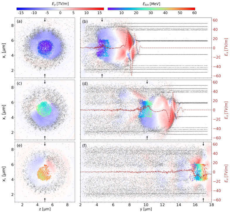
The load-bearing mechanism is the reduction of effective plasma density by geometric structuring. The target is made of carbon nanotube bundles (modeled as 25 nm-thick tubes at $10^{22}$ cm$^{-3}$) arranged in concentric shells with voids, giving a whole-target effective electron density of $10^{20}$ cm$^{-3}$; at this density the plasma frequency stays below the 800 nm laser frequency even after multiple ionization, so the pulse propagates and excites a wakefield bubble. The bubble, the same nonlinear structure familiar from gas-phase laser wakefield acceleration, traps electrons from the target walls and accelerates them in its rear, with the induced azimuthal magnetic field providing transverse focusing.
What would settle it
A direct test would be a higher-resolution particle-in-cell run with sub-nanometer cells and wall thickness closer to a physical nanotube (about 1 nm), keeping the same effective density; if the self-injected bunch charge or the >1 TeV/m gradient disappears, the central claim fails. A complementary experimental check would measure bunch charge and energy from an 800 nm pulse on a carbon nanotube target at an existing high-power infrared laser facility and compare with the simulated 867 pC and 27.9 MeV.
Extended reading notes
Core claim
On the paper's own terms, the discovery is that a solid-state nanostructured target can behave like a gaseous plasma for laser wakefield acceleration: the voids between carbon nanotube bundles lower the effective plasma density enough that an 800 nm pulse remains underdense, ionizes the carbon walls, and drives a nonlinear wakefield bubble in which electrons self-inject and are accelerated to tens of MeV over 15 $\mu$m. The paper reports a self-injected bunch of 867.5 pC charge with average kinetic energy 27.9 MeV and a maximum of 63.6 MeV, corresponding to average and peak gradients of 1.86 TeV/m and 4.24 TeV/m; it also reports a peak longitudinal accelerating field above 5 TV/m and an induced azimuthal magnetic field peaking near 50 kT. The authors present this as the first numerical evidence that TeV/m-scale acceleration is achievable with an infrared laser in a solid nanostructured target, not merely with ultraviolet or X-ray drivers.
Load-bearing premise
The simulation treats each carbon nanotube bundle as a 25 nm-thick uniform carbon wall at $10^{22}$ cm$^{-3}$ with one macroparticle per 25 nm cell, whereas real CNT walls are about 1 nm thick; the paper gives no convergence check showing that this coarse resolution preserves the wakefield bubble and the quoted beam parameters.
Editorial extensions
If this is right
- If the simulation is correct, TeV/m-scale wakefield acceleration no longer requires attosecond X-ray or ultraviolet drivers; an 800 nm laser, a standard high-power infrared source, can in principle do the job.
- The predicted bunch parameters (867 pC charge, few-fs duration, roughly 28 MeV average energy, and about 2 $\pi$ mm-mrad emittance) would make this scheme a candidate injector for ultrafast electron diffraction and other compact applications.
- The 50 kT-level induced magnetic field, if realized, could serve as a short-lived focusing element or an extreme-field source, although the paper treats it mainly as a transverse focusing mechanism.
- A proof-of-principle experiment using currently achievable laser parameters could test whether the predicted charge and gradients appear in a real carbon nanotube target.
Reading between the lines
- The 25 nm wall thickness is a coarse stand-in for real CNT bundles (individual tubes are about 1 nm thick); if finer resolution changes the effective density or the bubble structure, the exact numbers could shift, but the scheme's viability depends on the effective-density assumption rather than on wall thickness per se.
- The same effective-density design principle could be transferred to other nanostructured geometries, such as graphene multilayers or aligned tube forests, to match other driver wavelengths or to shape the plasma density radially and reduce the simulated divergence.
- The paper's reported dephasing and charge-intake dynamics at $10^{21}$ W/cm$^2$ suggest an optimal intensity window exists; a parameter scan over intensity, bore radius, and shell spacing might reveal a higher-charge, lower-energy-spread operating point.
- Because the carbon ion lattice remains nearly stationary over the acceleration time, the scheme might be extendable to solid-density targets beyond carbon, provided the underdense condition can be met.
Editorial analysis
A structured set of objections, weighed in public.
Referee Report
Summary. The paper reports fully 3D particle-in-cell simulations, using PIConGPU, of an 800 nm infrared laser pulse interacting with a structured target made of carbon nanotube bundles. The CNT bundles are modeled as 25 nm-thick homogeneous carbon tubes with an initial density of 1e22 cm^-3, arranged in concentric shells to reach an effective plasma density of 1e20 cm^-3. The laser (three cycles, 1e21 W/cm^2, 1.5 um spot size) ionizes the target, drives a wakefield bubble, and self-injects an electron bunch. At the end of a 15 um propagation, the authors report a bunch charge of 867.5 pC, average kinetic energy 27.9 MeV, maximum energy 63.6 MeV, and average and maximum gradients of 1.86 TeV/m and 4.24 TeV/m. A second case at 1e20 W/cm^2 yields a lower charge (0.12 nC). The paper claims this is the first numerical demonstration of TeV/m-scale acceleration driven by an infrared laser in a nanostructured solid target.
Significance. If the reported gradients and bunch parameters are robust, the result is significant: it would extend laser wakefield acceleration to structured solid-state targets driven by widely available 800 nm lasers, in contrast to the attosecond X-ray or ultraviolet drivers previously considered for solid-density plasmas. The simulation is a legitimate application of an established PIC code, and the acceleration result is emergent rather than a post-hoc fit to a predetermined model. The paper also provides a concrete target geometry, explicit laser parameters, and beam characterization (charge, energy spread, emittance, divergence), which are useful for planning experiments. However, the central numerical result is not yet established because the simulation resolution and particle statistics are not shown to be converged; the reported charge and gradient may depend on the discretization rather than on the physical target properties.
major comments (3)
- [Section 1 (Methods)] The simulation uses a uniform 25 nm mesh with one macroparticle per cell, and the modeled CNT wall thickness is also 25 nm (abstract and Fig. 1). No convergence study over mesh size or macroparticle number is presented. Because the wall is only one cell thick and the initial plasma density is 1e22 cm^-3, the target geometry and the ionization/wakefield dynamics may be dominated by the grid. Consequently, the central quantities quoted in Section 2.1 (867.5 pC bunch charge and 1.86 TeV/m average gradient) cannot yet be distinguished from numerical artifacts. I request a resolution study (e.g., 12.5 nm and 6.25 nm cell sizes, and a factor of 2-4 more macroparticles per cell) that demonstrates convergence of the bunch charge, energy spectrum, and longitudinal field amplitude.
- [Section 2.1 (Self-injection and acceleration; Figs. 5 and 6)] Self-injection into a wakefield bubble is a threshold process that is sensitive to small density perturbations. With one macroparticle per cell at near-solid density, the charge-density noise is of the order of the local density itself, so the sudden charge jump at t/T ~ 17 and the final 867.5 pC charge may be seeded by numerical shot noise. The paper does not quantify the noise level or show that the injection event is robust to particle-statistics changes. I recommend at least one additional simulation with more macroparticles per cell (or a quieter initialization) to verify that the injected charge and the time evolution in Figs. 5 and 6 are unchanged.
- [Section 2.3 (Effects on the ionic lattice)] The ion-displacement analysis validates the assumption of a nearly immobile carbon lattice, but it does not address electron-scale numerical convergence; the sentence "to the extent that the mesh and shape functions are acceptable" explicitly points to an untested assumption. Additionally, the text states that the bore-to-spot ratio Rin/w0 ~ 0.53 was optimized, but no sensitivity scan over this parameter is shown, even though it controls laser guiding and bubble formation. A scan over Rin/w0 (and ideally over the modeled wall thickness) is needed to support the claim that the adopted geometry is robust rather than a finely tuned special case.
minor comments (5)
- [Throughout] The manuscript uses "TV/m" and "TeV/m" interchangeably (for example, the Introduction and Sections 2.1 and 3); the standard TeV/m will eliminate ambiguity.
- [Section 1 (Methods)] In the sentence describing the mesh, "3 × 10⁸ mesh cells" should read "3 × 10^8 mesh cells" for clarity.
- [Section 2.1 (Fig. 6 discussion)] The text contains a typo "maximun" (should be "maximum").
- [Table 3] The FWHM energy spread is quoted as 105 percent, which is larger than the central energy; consider commenting on the strongly non-monoenergetic character of the bunch when discussing applications.
- [Section 3 (Conclusions)] The claim of being the "first numerical demonstration" would benefit from a direct comparison with Refs. [13] and [14] in the conclusions, stating explicitly what is new (infrared driver, self-injection into a bubble, TeV/m gradient) relative to those prior studies.
Circularity Check
No significant circularity: the central acceleration result is emergent from PIC simulation; only a minor non-load-bearing self-citation appears in target design.
full rationale
The central claim, self-injection of an 867.5 pC bunch at 27.9 MeV average energy and 1.86 TeV/m average gradient over 15 micrometers, is an output of the PIConGPU simulations, not a quantity reconstructed from a fitted formula. The effective-density approach of ref. 12 (Bonatto et al., with overlapping authorship) is used to choose a target geometry with ne approximately 10^20 cm^-3 and compatible laser parameters, but the simulated wakefield bubble, electron self-injection, bunch charge, and energy spectrum are emergent from the PIC run rather than imposed by that design input. The quoted gradients (27.9 MeV / 15 micrometers and 63.6 MeV / 15 micrometers) are the paper's own arithmetic definition of average and maximum gradient, not fitted or predicted variables. The self-citation to the effective-density method is minor and not load-bearing for the acceleration result: it is a parameter-selection convenience, and the result stands or falls on the numerical simulation, which is a separate computation. The remaining citations (ref. 13 graphene study, ref. 27 ion-lattice wakefields) are used as literature context or consistency checks and do not supply the central derivation. Therefore no step reduces a prediction to its input by construction; the paper is self-contained in its simulation-based derivation. Any convergence or modeling-fidelity concerns (25 nm mesh, one macroparticle per cell) are correctness risks, not circularity.
Assumptions & free parameters
free parameters (4)
- Effective plasma density ne =
1e20 cm^-3
- Bore-to-spot ratio Rin/w0 =
0.53
- CNT wall modeled thickness =
25 nm
- Macroparticles per cell =
1
assumptions (4)
- domain assumption The effective-density approach from prior work (ref 12) accurately predicts wakefield behavior in structured CNT targets.
- domain assumption Carbon atoms in the target are fully ionized (all six valence electrons) by the laser pulse on the timescale of the interaction.
- ad hoc to paper The PIC code with 25 nm cells and one macroparticle per cell adequately resolves the laser-plasma interaction in solid-density walls.
- domain assumption Carbon ion motion is negligible over the acceleration time.
Cite this review
Pith. "Pith review of Electron Acceleration in Carbon Nanotubes." pith.science (2026). https://pith.science/paper/GDIGHFIG
@misc{pith2026250200183,
  author       = {Pith},
  title        = {Pith review of: Electron Acceleration in Carbon Nanotubes},
  year         = {2026},
  howpublished = {\url{https://pith.science/paper/GDIGHFIG}},
  note         = {Machine review of arXiv:2502.00183}
}
abstract
Wakefield wavelengths associated with solid-state plasmas greatly limit the accelerating length. An alternative approach employs 2D carbon-based nanomaterials, like graphene or carbon nanotubes (CNTs), configured into structured targets. These nanostructures are designed with voids or low-density regions to effectively reduce the overall plasma density. This reduction enables the use of longer-wavelength lasers and also extends the plasma wavelength and the acceleration length. In this study, we present, to our knowledge, the first numerical demonstration of electron acceleration via self-injection into a wakefield bubble driven by an infrared laser pulse in structured CNT targets, similar to the behavior observed in gaseous plasmas for LWFA in the nonlinear (or bubble) regime. Using the PIConGPU code, bundles of CNTs are modeled in a 3D geometry as 25 nm-thick carbon tubes with an initial density of $10^{22}$ cm$^{-3}$. The carbon plasma is ionized by a three-cycle, 800 nm wavelength laser pulse with a peak intensity of $10^{21}$ W cm$^{-2}$, achieving an effective plasma density of $10^{20}$ cm$^{-3}$. The same laser also drives the wakefield bubble, responsible for the electron self-injection and acceleration. Simulation results indicate that fs-long electron bunches with hundreds of pC charge can be self-injected and accelerated at gradients exceeding 1~TeV$/$m. Both charge and accelerating gradient figures are unprecedented when compared with LWFA in gaseous plasma.
Figures


Figures from the paper (5 more)


Reference graph
Works this paper leans on
-
[1]
Tajima, T. & Dawson, J. M. Laser electron accelerator. Phys. Rev. Lett. 43, 267–270, DOI: 10.1103/PhysRevLett.43.267 (1979)
-
[2]
Chen, P., Su, J. J., Dawson, J. M., Bane, K. L. & Wilson, P. B. On Energy Transfer in the Plasma Wake Field Accelerator. Phys. Rev. Lett. 56, 1252–1255, DOI: 10.1103/PhysRevLett.56.1252 (1986)
-
[3]
Esarey, E., Schroeder, C. B. & Leemans, W. P. Physics of laser-driven plasma-based electron accelerators. Rev. Mod. Phys. 81, 1229–1285, DOI: 10.1103/RevModPhys.81.1229 (2009)
-
[4]
Gonsalves, A. et al. Petawatt laser guiding and electron beam acceleration to 8 GeV in a laser-heated capillary discharge waveguide. Phys. Rev. Lett. 122, 084801, DOI: 10.1103/physrevlett.122.084801 (2019)
- [5]
-
[6]
Labate, L. et al. Toward an effective use of laser-driven very high energy electrons for radiotherapy: Feasibility assessment of multi-field and intensity modulation irradiation schemes. Sci. Reports 10, DOI: 10.1038/s41598-020-74256-w (2020)
-
[7]
Assmann, R. W. et al. Eupraxia conceptual design report. The Eur. Phys. J. Special Top. 229, 3675–4284, DOI: 10.1140/epjst/e2020-000127-8 (2020)
-
[8]
Schroeder, C. B., Esarey, E., Geddes, C. G. R., Benedetti, C. & Leemans, W. P. Physics considerations for laser-plasma linear colliders. Phys. Rev. Special Top. - Accel. Beams 13, DOI: 10.1103/physrevstab.13.101301 (2010)
Show all 33 references
-
[9]
& Leemans, W
Schroeder, C., Benedetti, C., Esarey, E. & Leemans, W. Laser-plasma-based linear collider using hollow plasma channels. Nucl. Instruments Methods Phys. Res. Sect. A: Accel. Spectrometers, Detect. Assoc. Equip. 829, 113–116, DOI: 10.1016/j.nima.2016.03.001 (2016)
2016 doi
-
[10]
Facet-ii facility for advanced accelerator experimental tests
Yakimenko, V .et al. Facet-ii facility for advanced accelerator experimental tests. Phys. Rev. Accel. Beams 22, DOI: 10.1103/physrevaccelbeams.22.101301 (2019)
2019 doi
-
[11]
Laser acceleration in novel media
Tajima, T. Laser acceleration in novel media. The Eur. Phys. J. Special Top. 223, 1037–1044, DOI: 10.1140/epjst/ e2014-02154-6 (2014)
2014 doi
-
[12]
Bonatto, A. et al. Exploring ultra-high-intensity wakefields in carbon nanotube arrays: An effective plasma-density approach. Phys. Plasmas 30, DOI: 10.1063/5.0134960 (2023)
2023 doi
-
[13]
Author correction: Tev/m catapult acceleration of electrons in graphene layers
Bon¸ toiu, C.et al. Author correction: Tev/m catapult acceleration of electrons in graphene layers. Sci. Reports 13, DOI: 10.1038/s41598-023-29761-z (2023)
2023 doi
-
[14]
Dulat, A. et al. Coherent control of relativistic electron dynamics in plasma nanophotonics. Laser & Photonics Rev. DOI: 10.1002/lpor.202401570 (2024)
2024 doi
-
[15]
Thess, A. et al. Crystalline ropes of metallic carbon nanotubes. Science 273, 483–487, DOI: 10.1126/science.273.5274.483 (1996)
1996 doi
-
[16]
Fedeli, L. et al. Electron acceleration by relativistic surface plasmons in laser-grating interaction. Phys. Rev. Lett. 116, 015001, DOI: 10.1103/PhysRevLett.116.015001 (2016)
2016 doi
-
[17]
& Macchi, A
Sgattoni, A., Fedeli, L., Cantono, G., Ceccotti, T. & Macchi, A. High field plasmonics and laser-plasma acceleration in solid targets. Plasma Phys. Control. Fusion 58, 014004, DOI: 10.1088/0741-3335/58/1/014004 (2016)
2016 doi
-
[18]
Sahai, A. A. Nanomaterials based nanoplasmonic accelerators and light-sources driven by particle-beams. IEEE Access 9, 54831, DOI: 10.1109/ACCESS.2021.3070798 (2021)
2021
-
[19]
Sahai, A. A. et al. Petavolts per meter plasmonics: introducing extreme nanoscience as a route towards scientific frontiers. J. Instrumentation 18, P07019, DOI: 10.1088/1748-0221/18/07/P07019 (2023)
2023 doi
-
[20]
Burau, H. et al. Picongpu: A fully relativistic particle-in-cell code for a gpu cluster. IEEE Transactions on Plasma Sci. 38, 2831–2839, DOI: 10.1109/TPS.2010.2064310 (2010)
2010
-
[21]
See, C. H. & Harris, A. T. A review of carbon nanotube synthesis via fluidized-bed chemical vapor deposition,. Ind. I& Eng. Chem. Res. 46, 997 46, 997–1012, DOI: 10.1021/ie060955b (2007)
2007 doi
-
[22]
Sarasini, F. et al. Highly aligned growth of carbon nanotube forests with in-situ catalyst generation: A route to multifunc- tional basalt fibres. Compos. Part B: Eng. 243, 110136, DOI: 10.1016/j.compositesb.2022.110136 (2022). 10/11
2022
-
[23]
Schifano, E. et al. Plasma-etched vertically aligned cnts with enhanced antibacterial power. Nanomaterials 13, 1081, DOI: 10.3390/nano13061081 (2023)
2023 doi
-
[24]
Yadav, R. P.et al. Evaluation of vertical alignment in carbon nanotubes: A quantitative approach. Nucl. Inst. Methods Phys. Res. 1060, 169081, DOI: 10.1016/j.nima.2024.169081 (2024)
2024
-
[25]
Picksley, A. et al. Guiding of high-intensity laser pulses in 100-mm-long hydrodynamic optical-field-ionized plasma channels. Phys. Rev. Accel. Beams 23, 081303, DOI: 10.1103/PhysRevAccelBeams.23.081303 (2020)
2020 doi
-
[26]
& Eliezer, S
Loeb, A. & Eliezer, S. Free-electron laser and laser electron acceleration based on the megagauss magnetic fields in laser-produced plasmas. Phys. Rev. Lett. 56, 2252–2255, DOI: 10.1103/PhysRevLett.56.2252 (1986)
1986 doi
-
[27]
Hakimi, S. et al. Wakefield in solid state plasma with the ionic lattice force. Phys. Plasmas 25, 023112, DOI: 10.1063/1. 5016445 (2018)
2018 doi
-
[28]
& Goryashko, V
Salén, P., Opanasenko, A., Perosa, G. & Goryashko, V . State-of-the-art electron beams for compact tools of ultrafast science. Ultramicroscopy DOI: 10.1016/j.ultramic.2024.114080 (2024)
2024
-
[29]
Mittleman, D. M. et al. Recent advances in terahertz imaging. Appl. Phys. B 68, 1085, DOI: 10.1007/s003409900011 (1999)
1999 doi
-
[30]
& Sharma, R
Singh, M. & Sharma, R. P. Generation of thz radiation by laser plasma interaction. Contrib. Plasma Phys. 53, 540, DOI: 10.1002/ctpp.201300006 (2013)
2013 doi
-
[31]
Brochu, E., Cora, V . M. & de Freitas, N. A tutorial on bayesian optimization of expensive cost functions, with application to active user modeling and hierarchical reinforcement learning (2010). arXiv:1012.2599
2010 arXiv
-
[32]
https://eli-laser.eu
-
[33]
Acknowledgements We acknowledge the support received from the PIConGPU software developers and the STFC CDT LIV .DAT under grant agreement ST/P006752/1
https://www.clpu.es/eu/laser-vega-pw. Acknowledgements We acknowledge the support received from the PIConGPU software developers and the STFC CDT LIV .DAT under grant agreement ST/P006752/1. This work is supported by the Generalitat Valenciana under grant agreement CIDEGENT/20...
2019
Reviewed August 9, 2026 · model on record in the stance chip above.
Discussion (0). Continue with ORCID to comment.