REVIEW 3 major objections 5 minor 20 references
Measurement and Analysis of Scattering From Building Surfaces at Millimeter-Wave Frequency
T0 review · 3 major / 5 minor · reviewed 2026-08-09 · deepseek-v4-flash
Pith's one-line read Building-scatter models at 28 GHz need 3D receiver data, not just in-plane fits.
desk verdict Real 28 GHz building-scattering measurements with 3D receiver positions; the 3D-correction claim needs the missing out-of-plane FVU before it fully lands. read the letter →
The pith
A machine-rendered reading of the paper's core claim, the machinery that carries it, and where it could break.
The reading
What carries the argument
The load-bearing mechanism is the dual-lobe (backscattering) diffuse scattering model, which writes the scattered power at a receiving point as a weighted sum of a lobe centered on the specular-reflection direction and a lobe centered on the incident direction, with the balance set by $\Lambda$. The model parameters—scattering coefficient $S$, lobe-width factors $\alpha_R$ and $\alpha_i$, and balance $\Lambda$—are tuned by minimizing the fraction of variance unexplained (FVU) between measured and simulated total received power. An initial $S$ is obtained from surface roughness and the Fresnel reflection coefficient through $S = \sqrt{(1-R^2)\Gamma^2}$, using the roughness loss factor $R$. The argument's force comes from adding out-of-plane receiver positions to this fitting procedure, which changes the fitted parameters and improves predictions of backscatter outside the incident plane.
What would settle it
Extend the rough-wall measurement to receiver heights above 2.0 m (for example 2.1 to 2.5 m) and compare the measured power against the two fitted parameter sets: the incident-plane-only set ($S=0.60$, $\alpha_R=1$, $\alpha_i=10$, $\Lambda=0.2$) and the 3D set ($S=0.42$, $\alpha_R=6$, $\alpha_i=4$, $\Lambda=0.2$). If the incident-plane-only set matches the new out-of-plane heights as well as or better than the 3D set, the central claim would be refuted; if the 3D set clearly performs better, the claim is supported.
Extended reading notes
Core claim
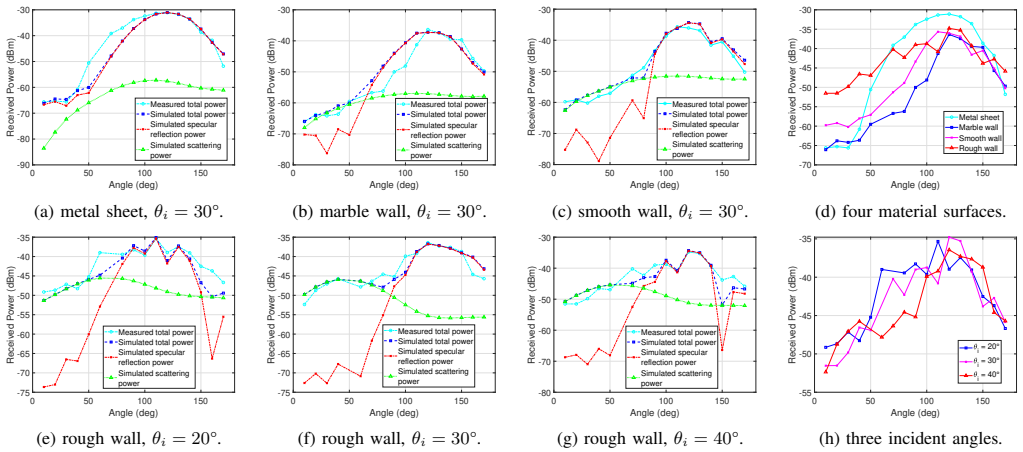
The paper's discovery, stated on its own terms, is that the diffuse scattering parameters of real building surfaces are three-dimensional quantities: they vary with incident angle and with receiver position in space, not just with material type. On the rough wall at 28 GHz, fitting the dual-lobe backscattering model to measured power only in the incident plane produced $S=0.60$, $\alpha_R=1$, $\alpha_i=10$, $\Lambda=0.2$, and that parameterization predicted out-of-plane backscatter power poorly, with FVU equal to 0.6742. Adding receiver positions at heights 10, 20, and 30 cm above the transmit height changed the fit to $S=0.42$, $\alpha_R=6$, $\alpha_i=4$, $\Lambda=0.2$ and lowered the unexplained variance to 0.6259, partially correcting the out-of-plane error while keeping the in-plane fit intact. For smoother surfaces, the single-lobe directive model with $\alpha_R=4$ and $S$ between roughly 0.11 and 0.28 matched the measurements; for the rough surface, the dual-lobe model was required, with $\Lambda$ increasing from 0.1 to 0.3 as the incident angle grew from 20° to 40°.
Load-bearing premise
The conclusions rest on the assumption that each measured power reading comes almost entirely from one specular reflection and one scattered path off the wall under test, with all other paths (ground, neighboring surfaces, higher-order reflections) more than 35 dB weaker and therefore treated as noise.
Editorial extensions
If this is right
- Channel models for air-to-ground millimeter-wave links should parameterize building-scatter models with receiver positions in three dimensions, not a single planar arc, because the incident-plane-only fit leaves FVU equal to 0.6742 at out-of-plane positions.
- The scattering coefficient of a given surface is angle-dependent: for the rough wall it rises from 0.45–0.55 at 40° incidence to 0.65–0.75 at 20°, so a single material label without incidence angle is not a sufficient description.
- For smoother surfaces, the single-lobe directive model with $\alpha_R=4$ suffices, while rough surfaces require the dual-lobe model with a backscattering component.
- The backscattering-lobe balance $\Lambda$ increases with incident angle (0.1 at 20°, 0.2 at 30°, 0.3 at 40°), so the relative strength of backscatter grows as incidence becomes more oblique.
- Parameter sets derived from one incident angle should not be transferred to other geometries; measurements at multiple angles and heights are required.
Reading between the lines
- If the 3D-fit claim holds, single-plane scattering measurements at other bands (for example sub-THz and THz) likely have the same out-of-plane blind spot, and repeating this measurement protocol at those bands would test whether the effect persists as the wavelength-to-roughness ratio changes.
- Because the paper integrates all power within a 5 ns excess-delay window, the fitted $S$, $\alpha_R$, $\alpha_i$, and $\Lambda$ are effective parameters that merge specular and diffuse arrivals; a higher-delay-resolution sounder could separate the two and test whether the dual-lobe model then splits into distinct components.
- The procedure suggests a practical calibration recipe for ray-tracing tools: a small number of receiver arcs at several heights around one wall point may be sufficient to fix the four scattering parameters, shortening outdoor measurement campaigns.
Signed reviews
Editorial analysis
A structured set of objections, weighed in public.
Referee Report
Summary. This paper reports 28 GHz bistatic diffuse-scattering measurements from a metal sheet and three building-wall surfaces (marble, smooth, rough) at incident angles of 20°, 30°, and 40°. The authors parameterize a directive or dual-lobe scattering model in the Wireless InSite ray tracer, using a roughness-based initial scattering coefficient from Eq. (4) and then minimizing the FVU metric of Eq. (7) to obtain S, αR, αi, and Λ for each surface. The central new claim, made in Section IV-A-4, is that fitting with receiver data at multiple heights (3D Rx space) yields different scattering parameters from fitting with incident-plane data alone, and that the 3D fit 'can partially correct' the out-of-plane error of the in-plane-only fit. The paper concludes that 3D receiving positions should be considered when parameterizing scattering from building surfaces.
Significance. The measurement campaign is valuable: real-world building surfaces at 28 GHz, multiple incident angles, and receiver positions outside the incident plane are underrepresented in the literature, and the paper provides a useful parameterization table for the four surfaces. The roughness-based initial S computed from Eq. (4) gives a physically grounded starting point. However, the paper's headline quantitative claim is not supported by the numbers as reported (see major comments), and the high in-sample FVU values mean the model fits are of limited accuracy. If the missing out-of-plane FVU for the 3D fit and a proper validation split confirm the claimed improvement, the conclusion would be an important practical message for mmWave channel modelers.
major comments (3)
- [Section IV-A-4, Fig. 6] The claim that the 3D-fitted parameter set (S=0.42, αR=6, αi=4, Λ=0.2) 'can partially correct' the out-of-plane error is not quantitatively supported, because the out-of-plane FVU for this parameter set is not reported. The paper reports only FVU=0.6742 for the in-plane-only fit evaluated out of plane, and FVU=0.6259 for the 3D fit evaluated in the incident plane. The latter is not the metric being corrected. Please report the out-of-plane FVU for both parameter sets, ideally per receiver height, and state whether the 3D fit actually reduces out-of-plane FVU relative to 0.6742; otherwise the conclusion rests on visual inspection of Fig. 6.
- [Section IV-A-2 and IV-A-4] All scattering parameters are fitted to the same measured positions that are later used for evaluation by minimizing FVU, so the agreement in Figs. 5 and 6 is in-sample. The reported minimum FVU values (0.2223 to 0.6273) are high, meaning a large fraction of the power variation remains unexplained even after fitting. To support the claim that the 3D fit generalizes better than the in-plane fit, please add a cross-validation or out-of-sample evaluation (e.g., fit on in-plane data and evaluate out of plane, or fit on a subset of heights and evaluate on the rest), and compare the fitted model against a baseline with specular reflection only. Also provide an estimate of the uncertainty of the fitted parameters.
- [Section IV-A-1] The assumption that one-hop reflection and one-hop scattering from the wall under test dominate the received power is load-bearing for the parameter fitting, but it is only stated, not demonstrated, for the out-of-plane receiver positions. The paper says other paths are more than 35 dB below the main path and are treated as noise, but no measured power delay profiles or ray-tracing path lists are shown to verify this at the non-zero receiver heights. If ground or adjacent-structure multipath is not negligible, the fitted S, αR, αi, and Λ will absorb the error, biasing the in-plane versus 3D comparison. Please show the residual multipath level at representative receiver positions or carry out a sensitivity analysis by adding and removing paths in the ray tracer.
minor comments (5)
- [Section II-A] The sentence following Eq. (2) contains a typo: 'the new reflection coefficient the for rough surface' should read 'the new reflection coefficient for the rough surface.'
- [Section II-B and Fig. 6] The heading 'Method for Calculating Initial Scatting Coefficient S' and the Fig. 6 caption 'Recevied power' contain typos; they should read 'Scattering' and 'Received', respectively.
- [Eq. (7)] The quantity defined in Eq. (7) is the square root of the fraction of unexplained variance (normalized RMSE), not the usual FVU; please clarify the definition or rename the metric to avoid confusion.
- [Section II-C] The notation 'αR, αi=1,2,...,10' should be written as 'αR, αi ∈ {1,2,...,10}' to avoid ambiguity about whether the two parameters are equal.
- [Section IV-A-1] Please clarify the relationship between the 5 ns maximum excess delay and the 1.5 m path-length-difference criterion, since at the speed of light these two thresholds correspond to the same delay; state which one is used to select paths.
Circularity Check
No significant circularity; the parameterization is in-sample fitting transparently reported, and the central 3D claim rests on a genuine out-of-plane generalization test.
full rationale
The derivation chain is not circular. The scattering models in Eqs. (5)-(6) and the roughness loss factor in Eqs. (1)-(2) are adopted from prior literature and are not derived from the measured data. The theoretical scattering coefficient S in Eq. (4) is computed from independent inputs (roughness hrms and permittivity in Table I) via the stated conservation-of-energy relation, giving an initial value that is then refined by fitting. The fitting procedure is explicit: Section IV-A-2 states that parameters are adjusted to minimize FVU (Eq. 7) and the process is repeated until the optimal parameters are obtained. Table II therefore reports the minimized objective, which is a fitting diagnostic rather than an independent prediction, so no fitted input is renamed as a prediction. The central claim about 3D receiving space is supported by a legitimate out-of-sample comparison: the incident-plane-only parameter set (S=0.60, alpha_R=1, alpha_i=10, Lambda=0.2) is evaluated at out-of-plane Rx heights and yields FVU=0.6742 (Section IV-A-4), which is a held-out evaluation. The claimed partial correction by the 3D fit is less quantitatively supported because the paper reports only the in-plane FVU=0.6259 for that fit and relies on visual inspection of Fig. 6 for the out-of-plane improvement; however, under-support is an evidentiary gap, not circularity. The only self-citation, Ref. [20] by co-author S. Sun, is used for the far-field criterion and is not load-bearing to the main conclusion. No step reduces, by the paper's own equations or by a self-citation chain, to its own inputs.
Assumptions & free parameters
free parameters (4)
- Scattering coefficient S =
metal: 0.05-0.15; marble: 0.10-0.20; smooth wall: 0.20-0.30; rough wall: 0.65-0.75 (20 degrees), 0.55-0.65 (30…
- Lobe width factor alpha_R =
4 for metal/marble/smooth wall; 1 for rough wall; 6 in 3D fit
- Backscatter lobe width alpha_i =
10 for rough wall; 4 in 3D fit
- Backscatter proportion Lambda =
0.1 (20 degrees), 0.2 (30 degrees), 0.3 (40 degrees) for rough wall; 0.2 in Fig. 7 and 3D fit
assumptions (7)
- domain assumption The Beckmann-Kirchhoff roughness factor R in Eq. (2) accurately describes the specular reflection loss for the measured surfaces at small incident angles.
- domain assumption Energy conservation expressed by Eq. (3) holds with negligible transmission through the wall.
- domain assumption The directive and dual-lobe scattering models (Eqs. 5-6) describe the angular distribution of diffuse scattering for building surfaces.
- domain assumption The surface permittivity and rms roughness values in Table I accurately represent the measured surfaces.
- domain assumption One-hop reflection and one-hop scattering paths dominate the received power; other paths are more than 35 dB below the main path and treated as noise.
- domain assumption The center of the wall is in the far field of both antennas, so plane-wave incidence and far-field scattering formulas apply.
- domain assumption Received power within 5 ns excess delay and path-length difference within 1.5 m captures all relevant specular and scattering energy.
Cite this review
Pith. "Pith review of Measurement and Analysis of Scattering From Building Surfaces at Millimeter-Wave Frequency." pith.science (2026). https://pith.science/paper/Z56G4MBV
@misc{pith2026250200699,
  author       = {Pith},
  title        = {Pith review of: Measurement and Analysis of Scattering From Building Surfaces at Millimeter-Wave Frequency},
  year         = {2026},
  howpublished = {\url{https://pith.science/paper/Z56G4MBV}},
  note         = {Machine review of arXiv:2502.00699}
}
read the original abstract
In future air-to-ground integrated networks, the scattering effects from ground-based scatterers, such as buildings, cannot be neglected in millimeter-wave and higher frequency bands, and have a significant impact on channel characteristics. However, current scattering measurement studies primarily focus on single incident angles within the incident plane, leading to insufficient characterization of scattering properties. In this paper, we present scattering measurements conducted at 28 GHz on various real-world building surfaces with multiple incident angles and three-dimensional (3D) receiving angles. The measured data are analyzed in conjunction with parameterized scattering models in ray tracing and numerical simulations. Results indicate that for millimeter-wave channel modeling near building surfaces, it is crucial to account not only for surface materials but also for the scattering properties of the building surfaces with respect to the incident angle and receiving positions in 3D space.
Figures


Figures from the paper (4 more)



Reference graph
Works this paper leans on
-
[1]
A survey of air-to-ground propagation channel modeling for unmanned aerial vehicles,
W. Khawaja et al ., “A survey of air-to-ground propagation channel modeling for unmanned aerial vehicles,” IEEE Commun. Surveys Tuts. , vol. 21, no. 3, pp. 2361–2391, thirdquarter 2019
work page 2019
-
[2]
UA V air-to-ground channel characterization for mmWave systems,
W. Khawaja et al ., “UA V air-to-ground channel characterization for mmWave systems,” in Proc. IEEE Veh. Technol. Conf. , Toronto, ON, Canada, Sep. 2017, pp. 1–5
work page 2017
-
[3]
Optimum hovering locations with angular domain user separation for cooperative UA V networks,
N. Rupasinghe et al., “Optimum hovering locations with angular domain user separation for cooperative UA V networks,” in Proc. IEEE Global Telecommun. Conf. , 2016, pp. 1–6
work page 2016
-
[4]
CmWave and Sub-THz: Key Radio Enablers and Complementary Spectrum for 6G
M. V . Katwe et al. , “CmWave and sub-THz: Key radio en- ablers and complementary spectrum for 6G,” [Online]. Available: https://arxiv.org/pdf/2406.18391
-
[5]
Beckmann et al ., The Scattering of Electromagnetic Waves From Rough Surfaces
P. Beckmann et al ., The Scattering of Electromagnetic Waves From Rough Surfaces. Norwood, MA: Artech House, 1987
work page 1987
-
[6]
Measurement and modeling of scattering from buildings,
V . Degli-Esposti et al., “Measurement and modeling of scattering from buildings,” IEEE Trans. on Ant. and Prop. , vol. 55, no. 1, pp. 143–153, Jan 2007
work page 2007
-
[7]
T. S. Rappaport, Wireless Communications: Principles and Practice, 2nd ed. Upper Saddle River, NJ: Prentice Hall, 2002
work page 2002
-
[8]
Scattering mechanisms and modeling for terahertz wireless communications,
S. Ju et al., “Scattering mechanisms and modeling for terahertz wireless communications,” in Proc. IEEE Int. Conf. Commun. , May 2019, pp. 1–7
work page 2019
Show all 20 references
-
[9]
Guo et al., ”Diffuse scattering analysis of indoor propagation channel at terahertz frequency,” Proc
G. Guo et al., ”Diffuse scattering analysis of indoor propagation channel at terahertz frequency,” Proc. IEEE Wireless Commun. Netw. Conf., Apr. 2024, pp. 1–6
2024
-
[10]
On the importance of diffuse scattering model parameterization in indoor wireless channels at mmWave frequencies,
J. Pascual-Garcia et al., “On the importance of diffuse scattering model parameterization in indoor wireless channels at mmWave frequencies,” IEEE Access, vol. 4, pp. 688-701, Feb. 2016
2016
-
[11]
Diffuse scattering directive model parameterization method for construction materials at mmWave frequencies,
M.-H. Ren et al ., “Diffuse scattering directive model parameterization method for construction materials at mmWave frequencies,” Int. J. Antennas Propag., vol. 2020, pp. 1–9, Dec. 2020
2020
-
[12]
Effect level based parameterization method for diffuse scattering models at millimeter-wave frequencies,
H. Tian et al ., “Effect level based parameterization method for diffuse scattering models at millimeter-wave frequencies,” IEEE Access, vol. 7, pp. 93286–93293, 2019
2019
-
[13]
Boithias et al., Radio wave propagation
L. Boithias et al., Radio wave propagation. McGraw-Hill NY , 1987
1987
-
[14]
Evaluation of the role of diffuse scattering in urban microcellular propagation,
V . Degli-Esposti and H. L. Bertoni, “Evaluation of the role of diffuse scattering in urban microcellular propagation,” in Proc. IEEE Veh. Tech- nol. Conf. , Amsterdam, The Netherlands, Sep. 1999, pp. 1392–1396
1999
-
[15]
Full-wave simulation and scattering modeling for terahertz communications,
H. Yi et al., “Full-wave simulation and scattering modeling for terahertz communications,” IEEE J. Sel. Topics Signal Process. , vol. 17, no. 4, pp. 1–16, Nov. 2023
2023
-
[16]
Terahertz wave propagation characteristics on rough surfaces based on full-wave simulations,
P. Xie et al ., “Terahertz wave propagation characteristics on rough surfaces based on full-wave simulations,” Radio Sci. , vol. 57, no. 6, 2022, Art. no. e2021RS007385
2022
-
[17]
Millimeter-wave channel measurements and analysis for statistical spatial channel model in in-building and urban environments at 28 GHz
J. Ko et al ., “Millimeter-wave channel measurements and analysis for statistical spatial channel model in in-building and urban environments at 28 GHz”, IEEE Trans. Wireless Commun., vol. 16, no. 9, pp. 5853-5868, Sep. 2017
2017
-
[18]
Small-scale, local area, and transitional millime- ter wave propagation for 5G communications,
T. S. Rappaport et al., “Small-scale, local area, and transitional millime- ter wave propagation for 5G communications,” IEEE Trans. on Ant. and Prop., vol. 65, no. 12, pp. 6474-6490, Dec. 2017
2017
-
[19]
The comparative study of S–V model between 3.5 and 28 GHz in indoor and outdoor scenarios
T. Jiang et al., “The comparative study of S–V model between 3.5 and 28 GHz in indoor and outdoor scenarios”, IEEE Trans. Veh. Technol. , vol. 69, no. 3, pp. 2351-2364, Mar. 2020
2020
-
[20]
How to differentiate between near field and far field: Revisiting the Rayleigh distance,
S. Sun et al ., “How to differentiate between near field and far field: Revisiting the Rayleigh distance,” IEEE Commun. Magazine , vol. 63, no. 1, pp. 22-28, Jan. 2025
2025
Reviewed August 9, 2026 · model on record in the stance chip above.
Discussion (0). Continue with ORCID to comment.