REVIEW 2 major objections 4 minor 26 references
Tri-band Aperture-shared Antenna Array Using Scalable FSS-based Electromagnetic Transparent Structure
T0 review · 2 major / 4 minor · reviewed 2026-08-07 · deepseek-v4-flash
Pith's one-line read Building the low-band dipole from a frequency-selective skin lets one aperture serve three bands without shading the higher-band antennas.
desk verdict Solid, well-executed antenna design with a new dual-transparent FSS; the headline <0.6 dB gain-deviation claim rests on simulation only, so the paper needs a small but honest revision. read the letter →
The pith
A machine-rendered reading of the paper's core claim, the machinery that carries it, and where it could break.
The reading
What carries the argument
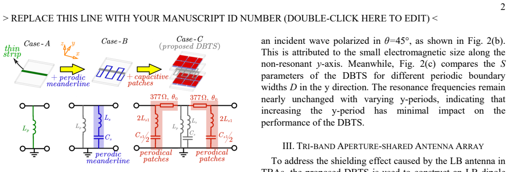
The central object is the DBTS unit cell, an FSS whose equivalent circuit starts from a thin strip acting as a shunt inductor $L_p$ and gains two serial $L_s$-$C_s$ resonant tanks, one from a meander line and one from capacitive patches; each tank opens one transmission passband, and the air gaps between laminates are modeled as transmission lines. The inductance and capacitance values come from published formulas and equivalent-circuit extraction, so both passband frequencies are tunable by geometry and additional passbands are introduced by adding more L-C tanks. Inside the low-band dipole, the same DBTS pattern is used with a coupled-line middle section designed to preserve the passbands, and the authors argue the open boundary along the non-resonant direction is the limit of the nearly period-insensitive periodic design.
What would settle it
Measure or simulate the exact finite low-band radiator alone (the coupled-line DBTS dipole arm with open boundaries) and check whether transmission remains above about -1 dB at 1.92-2.18 GHz and 3.3-3.8 GHz; if the passbands shift or close, the restored higher-band patterns cannot be attributed to the element's transparency.
Extended reading notes
Core claim
A dual-band electromagnetic transparent structure (DBTS), formed by loading a meander line and capacitive patches onto an inductive strip, can serve as the radiator of a low-band dipole while remaining nearly transparent in two higher bands. In the array built here, those passbands cover 1.92-2.18 GHz and 3.3-3.8 GHz, and the measured low-, middle-, and high-band reflections are all below -10 dB. Compared with a conventional low-band dipole, the transparent dipole restores the middle- and high-band radiation patterns to nearly the case with no low-band element at all, with broadside gain deviation below 0.6 dB. The paper interprets this as evidence that the shielding effect of the low-band element is essentially eliminated, enabling a compact triple-band shared aperture.
Load-bearing premise
The load-bearing premise is that the DBTS designed under infinite periodic boundary conditions keeps its two passbands when truncated into the finite, coupled-line form used in the low-band dipole, argued from insensitivity to the y-direction period rather than a direct simulation of the exact finite element.
Editorial extensions
If this is right
- Adding another serial L-C tank to the DBTS should open a third passband, so the same low-band dipole concept can extend to four or more operational bands.
- Base-station panels can interleave middle- and high-band antennas in the same physical aperture occupied by the low-band dipole instead of stacking them above it.
- Measured reflections below -10 dB in the three bands indicate the element set can cover 2G/3G/4G/5G cellular allocations from one structure.
- The reported 100% aperture reuse ratio at the high band and 51% at the middle band follow from the reduced shielding, meaning more antenna elements fit in a fixed panel footprint.
Reading between the lines
- A direct next experiment is to build a three-tank version of the DBTS and verify that a third transmission band appears while the low-band dipole still radiates correctly, since the paper establishes the two-band case only.
- The transparency assessment is made at broadside and at three azimuth cuts, so testing the same dipole under oblique incidence near the edges of a sector beam would show whether the shielding suppression survives scanning.
- The coupled-line middle segment is tuned indirectly; deriving its equivalent circuit explicitly would let designers scale the dipole length without full-wave resimulation of every variant.
Editorial analysis
A structured set of objections, weighed in public.
Referee Report
Summary. The manuscript proposes a dual-band electromagnetic transparent structure (DBTS) built from an inductive strip loaded with meander lines and capacitive patches, and uses it to realize a low-band (LB) dipole for a tri-band aperture-shared base-station array. The DBTS is designed to have passbands at the middle band (MB, 1.92–2.18 GHz) and high band (HB, 3.3–3.8 GHz), while the LB dipole operates at 0.65–0.88 GHz. Full-wave simulations compare three configurations: the MB/HB sub-array alone, with a conventional LB dipole, and with the DBTS-based LB dipole; the last case shows radiation patterns nearly identical to the LB-free case, with broadside gain deviation below 0.6 dB. A prototype is fabricated and measured, showing reflection coefficients below –10 dB in the three bands and renormalized patterns in reasonable agreement with simulations. The paper claims that the DBTS-based LB dipole effectively restores MB/HB radiation performance and provides frequency scalability through additional L-C tanks.
Significance. The paper addresses a real problem in multiband base-station arrays and offers a systematic FSS-based route to reducing LB shielding. The main strengths are the full-wave Case-I/II/III comparison, the fabricated prototype with measured S-parameters and patterns, and the quantitative aperture-reuse comparison in Table I. If the claims are correct, the design is a useful step toward compact tri-band shared-aperture arrays. The principal weakness is that the headline 'less than 0.6 dB' gain-deviation claim is supported only by simulation; the measurements do not include a no-LB-dipole baseline, and the measured gain offset (0.5–1 dB) is comparable in size to the claimed effect. The paper would be significantly strengthened by adding such a baseline or by clearly qualifying the claim as simulation-only.
major comments (2)
- [Sec. IV, Fig. 7] The abstract and conclusion state that the DBTS-based LB dipole restores radiation performance with broadside gain deviation below 0.6 dB. This figure comes from the full-wave comparison of Case-I and Case-III in Sec. III-B, but the measured results in Sec. IV contain no Case-I baseline. The measured broadside gains for the full array are 0.5–1 dB below simulation (attributed to cable/adaptor loss), which is the same order of magnitude as the claimed improvement; consequently the measurement cannot confirm the 0.6 dB restoration claim. Please either add a measured Case-I (array without the LB dipole) comparison, or explicitly state that the <0.6 dB deviation is a simulated result and discuss the measurement limitation.
- [Sec. II, abstract] The abstract and Sec. II claim that the DBTS features 'flexible frequency band scalability by loading additional serial L-C tanks.' The only evidence is that Case-C has two passbands while Case-B has one, which is a suggestion rather than a demonstration. Since 'Scalable' appears in the title and is presented as a key contribution, I ask the authors to provide a concrete example (e.g., a third passband obtained by adding another L-C tank, verified by full-wave simulation or measurement) or to temper the claim to what is actually shown.
minor comments (4)
- [Sec. II, Fig. 2] The DBTS transmission response is characterized for periodic boundary conditions at normal incidence only (θ=0° and 45°). In the final array, the LB dipole is illuminated by the MB/HB antennas in the near field, so the plane-wave normal-incidence FSS response is not directly representative of the operating condition. Although the full-wave Case-III simulation in Sec. III-B does model the actual configuration and largely mitigates this concern, the FSS-level characterization would be more convincing if oblique incidence were reported, or if the text explicitly stated that the periodic-boundary response is merely an indicator and the integrated Case-III simulation is the validation.
- [Sec. IV, Eq. (1)] The aperture reuse ratio is referenced as Eq. (1), but the equation itself is not displayed in the manuscript text provided. Please ensure the formula is present and explicitly defined, since Table I relies on this metric for the comparison.
- [Sec. IV, Fig. 7 caption] The caption of Fig. 7(b) reads 'Reflection coefficient and isolation within same element for ports...'; the phrase 'isolation within same element' is ambiguous. It likely means reflection coefficient at each port and isolation between ports of the same element; please clarify.
- [Abstract] There are minor typographical and language issues, e.g., 'Th e LB dipole' in the abstract and the awkward phrase 'is firstly proposed.' A light language edit is recommended.
Circularity Check
No significant circularity: the DBTS passbands are calibrated design targets, and the <0.6 dB gain-deviation claim is a direct full-wave comparison rather than a reduction to the design inputs.
full rationale
No step in the derivation chain reduces to its own inputs by construction. The DBTS passbands are design targets realized by choosing circuit element values (Ls1, Cs1, Lp, Ls, Cs) with slight parameter tuning; the equivalent circuit is then validated against full-wave simulation, so this is a calibration and modeling exercise, not a prediction of an independent quantity. The headline claim that the LB dipole causes minimal shielding, with broadside gain deviation below 0.6 dB, is obtained from a direct full-wave comparison of Case-I (no LB dipole), Case-II (traditional LB dipole), and Case-III (DBTS-based LB dipole) at MB and HB, as shown in Figs. 4-6; it is not computed from the DBTS passband frequencies or from a fitted parameter. The only extrapolation is from periodic-boundary characterization of the DBTS to the finite, coupled-line LB dipole, and the paper addresses this with the y-period insensitivity study and treats the open boundary as the limiting case of an infinite period; this is an engineering assumption rather than a circular reduction. The absence of a measured no-LB-dipole baseline is a validation limitation, not a circularity. Existing citations, including [18] and [23], are used for context, comparison, or standard equivalent-circuit extraction methods and are not load-bearing for the central claim.
Assumptions & free parameters
free parameters (2)
- DBTS circuit values (Ls1, Cs1, Ls, Cs) =
0.1 nH, 0.28 pF, 45.7 nH, 0.0915 pF
- Coupled-line width in LB dipole middle section =
not stated explicitly, dimensions W1=2.95 mm, W2=6.7 mm given
assumptions (3)
- domain assumption The equivalent circuit of the FSS (shunt inductor with serial L-C tanks) accurately represents the full-wave electromagnetic behavior.
- domain assumption The open boundary in the non-resonant y-direction of the finite LB dipole behaves like an infinite periodic boundary, preserving the passbands.
- domain assumption The DBTS transmission remains high for oblique incidence angles corresponding to the sub-array beam.
Cite this review
Pith. "Pith review of Tri-band Aperture-shared Antenna Array Using Scalable FSS-based Electromagnetic Transparent Structure." pith.science (2026). https://pith.science/paper/QRC66GXW
@misc{pith2026250520114,
  author       = {Pith},
  title        = {Pith review of: Tri-band Aperture-shared Antenna Array Using Scalable FSS-based Electromagnetic Transparent Structure},
  year         = {2026},
  howpublished = {\url{https://pith.science/paper/QRC66GXW}},
  note         = {Machine review of arXiv:2505.20114}
}
read the original abstract
In a tri-band aperture-shared array (TBA), the low-band (LB) dipole often deteriorates the radiation patterns of the middle-band (MB) and high-band (HB) antennas due to shielding effects. To address this issue, a novel dual-band electromagnetic transparent structure (DBTS) is firstly proposed and used to realize a TBA. The DBTS achieves two tunable electromagnetic transparent frequency bands by periodically loading capacitive patches and meander lines to an inductive strip. Meanwhile, the DBTS features flexible frequency band scalability by loading additional serial L-C tanks. Then the DBTS is utilized to construct the LB dipole of a TBA, with its electromagnetic transparent bands allocated at MB and HB simultaneously. The proposed array realizes an aperture-shared operation within the frequency ranges covering 0.65-0.88 GHz (LB), 1.92-2.18 GHz (MB) and 3.3-3.8 GHz (HB). The LB dipole induces minimal shielding to the MB and HB antennas, resulting in their restored radiation performance with broadside gain deviation of less than 0.6 dB.
Figures


Figures from the paper (4 more)


Reference graph
Works this paper leans on
-
[1]
Helical Torsion Coaxial Cable for Dual-Band Shared-Aperture Antenna Array Decoupling,
Y. Zhu, Y. Chen, and S. Yang, “Helical Torsion Coaxial Cable for Dual-Band Shared-Aperture Antenna Array Decoupling,” IEEE Trans. Antennas Propag. , vol. 68, no. 8, pp. 6128–6135, Aug. 2020, doi: 10.1109/TAP.2020.2986725
-
[2]
Y. Chen, J. Zhao, and S. Yang, “A Novel Stacked Antenna Configuration and its Applications in Dual-Band Shared-Aperture Base Station Antenna Array Designs,” IEEE Trans. Antennas Propag. , vol. 67, no. 12, pp. 7234–7241, Dec. 2019, doi: 10.1109/TAP.2019.2930136
-
[3]
Y. Zhu, Y. Chen, and S. Yang, “Decoupling and Low-Profile Design of Dual-Band Dual-Polarized Base Station Antennas Using Frequency- Selective Surface,” IEEE Trans. Antennas Propag. , vol. 67, no. 8, pp. 5272–5281, Aug. 2019, doi: 10.1109/TAP.2019.2916730
-
[5]
Broadband Dual- Polarized Element With Rotated Sle eve Arms for Compact Dual-Band Antenna,
X. W. Dai, C. Ding, F. Zhu, L. Liu, and G. Q. Luo, “Broadband Dual- Polarized Element With Rotated Sle eve Arms for Compact Dual-Band Antenna,” IEEE Antennas Wirel. Propag. Lett. , vol. 20, no. 12, pp. 2519–2523, Dec. 2021, doi: 10.1109/LAWP.2021.3117037
arXiv 2021
-
[6]
Scattering Suppression in a 4G and 5G Base Station Antenna Array Using Spiral Chokes,
H.-H. Sun, H. Zhu, C. Ding, B. Jones, and Y. J. Guo, “Scattering Suppression in a 4G and 5G Base Station Antenna Array Using Spiral Chokes,” IEEE Antennas Wirel. Propag. Lett. , vol. 19, no. 10, pp. 1818–1822, Oct. 2020, doi: 10.1109/LAWP.2020.3019930
arXiv 2020
-
[7]
Suppression of Cross-Band Scattering in Multiband Antenna Arrays,
H.-H. Sun, C. Ding, H. Zhu, B. Jones, and Y. J. Guo, “Suppression of Cross-Band Scattering in Multiband Antenna Arrays,” IEEE Trans. Antennas Propag. , vol. 67, no. 4, pp. 2379–2389, Apr. 2019, doi: 10.1109/TAP.2019.2891707
-
[8]
Suppression of Cross-Band Coupling Interference in Tri-Band Shared-Aperture Base Station Antenna,
Y.-L. Chang and Q.-X. Chu, “Suppression of Cross-Band Coupling Interference in Tri-Band Shared-Aperture Base Station Antenna,” IEEE Trans. Antennas Propag., vol. 70, no. 6, pp. 4200–4214, Jun. 2022, doi: 10.1109/TAP.2021.3138531
-
[9]
Dual-Band Aperture Shared Antenna Array With Decreased Radiation Pattern Distortion,
W. Niu, B. Sun, G. Zhou, and Z. Lan, “Dual-Band Aperture Shared Antenna Array With Decreased Radiation Pattern Distortion,” IEEE Trans. Antennas Propag. , vol. 70, no. 7, pp. 6048–6053, Jul. 2022, doi: 10.1109/TAP.2022.3161267
arXiv 2022
Show all 26 references
-
[10]
Suppression of Cross-Band Scattering in Interleave d Dual-Band Cellular Base-Station Antenna Arrays,
H.-H. Sun, B. Jones, Y. J. Guo, and Y. H. Lee, “Suppression of Cross-Band Scattering in Interleave d Dual-Band Cellular Base-Station Antenna Arrays,” IEEE Access, vol. 8, pp. 222486–222495, 2020, doi: 10.1109/ACCESS.2020.3043578
2020
-
[11]
Self-Decoupled Dual-Band Dual-Polarized Aperture-Shared Antenna Array,
S. J. Yang, R. Ma, and X. Y. Zhang, “Self-Decoupled Dual-Band Dual-Polarized Aperture-Shared Antenna Array,” IEEE Trans. Antennas Propag. , vol. 70, no. 6, pp. 4890–4895, Jun. 2022, doi: 10.1109/TAP.2021.3137531
2022
-
[12]
A Filtering and Electromagnetic- Transparent Antenna for Triple-Ba nd Aperture-Shared Base Station Antenna Array,
W. Niu, B. Sun, and X. Hua ng, “A Filtering and Electromagnetic- Transparent Antenna for Triple-Ba nd Aperture-Shared Base Station Antenna Array,” IEEE Antennas Wirel. Propag. Lett. , vol. 23, no. 1, pp. 244–248, Jan. 2024, doi: 10.1109/LAWP.2023.3322414
2024
-
[13]
In-Band Mutual Coupling Suppression in Dual-Band Shared-Aperture Base Station Arrays Using Dielectric Block Loading,
Y. Da, X. Chen, and A. A. Kishk, “In-Band Mutual Coupling Suppression in Dual-Band Shared-Aperture Base Station Arrays Using Dielectric Block Loading,” IEEE Trans. Antennas Propag. , vol. 70, no. 10, pp. 9270–9281, Oct. 2022, doi: 10.1109/TAP.2022.3177496
2022
-
[14]
Dual- Polarized Dipole Antenna With Dual -Band Spatial Filtering Response for Aperture-Shared Triband Ba se Station Array Application,
P. Liu, F. Jia, Y. Zhang, G. Su, Q. Wang, and X. Y. Zhang, “Dual- Polarized Dipole Antenna With Dual -Band Spatial Filtering Response for Aperture-Shared Triband Ba se Station Array Application,” IEEE Antennas Wirel. Propag. Lett. , vol. 22, no. 12, pp. 3057–3061, Dec. 2023, d...
2023
-
[15]
Dual-Band Shared-Aperture Base Station Antenna Array With El ectromagnetic Transparent Antenna Elements,
D. He, Q. Yu, Y. Chen, and S. Yang, “Dual-Band Shared-Aperture Base Station Antenna Array With El ectromagnetic Transparent Antenna Elements,” IEEE Trans. Antennas Propag. , vol. 69, no. 9, pp. 5596– 5606, Sep. 2021, doi: 10.1109/TAP.2021.3061151
2021
-
[16]
Cross-Band Mutual Coupling Reduction in Dual-Band Base-Station Antennas With a Novel Grid Frequency Selective Surface,
Y. Zhu, Y. Chen, and S. Yang, “Cross-Band Mutual Coupling Reduction in Dual-Band Base-Station Antennas With a Novel Grid Frequency Selective Surface,” IEEE Trans. Antennas Propag. , vol. 69, no. 12, pp. 8991–8996, Dec. 2021, doi: 10.1109/TAP.2021.3098514
2021
-
[17]
Triband Dual-Polarized Shared-Aperture Antenna for 2G/3G/4G/5G Base Sta tion Applications,
G.-N. Zhou, B.-H. Sun, Q.-Y. Liang, S.-T. Wu, Y.-H. Yang, and Y.-M. Cai, “Triband Dual-Polarized Shared-Aperture Antenna for 2G/3G/4G/5G Base Sta tion Applications,” IEEE Trans. Antennas Propag., vol. 69, no. 1, pp. 97–108, Jan. 2021, doi: 10.1109/TAP.2020.3016406
2021
-
[18]
Low Scattering Element- Based Aperture-Shared Array for Multiband Base Stations,
S. J. Yang, Y. Yang, and X. Y. Zhang, “Low Scattering Element- Based Aperture-Shared Array for Multiband Base Stations,” IEEE Trans. Antennas Propag. , vol. 69, no. 12, pp. 8315–8324, Dec. 2021, doi: 10.1109/TAP.2021.3083760
2021
-
[19]
A Mutual-Coupling-Suppressed Dual-Band Dual- Polarized Base Station Antenna Using Multiple Folded-Dipole Antenna,
X. Liu et al. , “A Mutual-Coupling-Suppressed Dual-Band Dual- Polarized Base Station Antenna Using Multiple Folded-Dipole Antenna,” IEEE Trans. Antennas Propag. , vol. 70, no. 12, pp. 11582–11594, Dec. 2022, doi: 10.1109/TAP.2022.3209177
2022
-
[20]
A Quadruple-Band Shared-Aperture Antenna Array W ith Multiband Radiation Pattern Restorations,
Y. Jia, H. Zhai, J. Yin, Y. Wang, and Y. Liu, “A Quadruple-Band Shared-Aperture Antenna Array W ith Multiband Radiation Pattern Restorations,” IEEE Trans. Antennas Propag. , vol. 72, no. 10, pp. 7722–7735, Oct. 2024, doi: 10.1109/TAP.2024.3439874
2024
-
[21]
A Systematic Approach to Design Spatial Filtenna for Aperture-Shared Base-Station Array,
Y. Wang, H. Su, R. C. Dai, L. T. Chen, L. H. Ye, and X. Y. Zhang, “A Systematic Approach to Design Spatial Filtenna for Aperture-Shared Base-Station Array,” IEEE Trans. Antennas Propag., vol. 71, no. 10, pp. 7792–7803, Oct. 2023, doi: 10.1109/TAP.2023.3299409
2023
-
[22]
Electromagnetic Transparent Antenna With Slot-Loaded Patch Dipoles in Dual-Band Array,
Y.-S. Wu, Q.-X. Chu, and H.-Y. Huang, “Electromagnetic Transparent Antenna With Slot-Loaded Patch Dipoles in Dual-Band Array,” IEEE Trans. Antennas Propag. , vol. 70, no. 9, pp. 7989–7998, Sep. 2022, doi: 10.1109/TAP.2022.3164194
2022
-
[23]
Aperture-Shared Dual-Band Antennas With Partia lly Reflecting Surfaces for Base- Station Applications,
Y. Qin, R. Li, Q. Xue, X. Zhang, and Y. Cui, “Aperture-Shared Dual-Band Antennas With Partia lly Reflecting Surfaces for Base- Station Applications,” IEEE Trans. Antennas Propag., vol. 70, no. 5, pp. 3195–3207, May 2022, doi: 10.1109/TAP.2021.3137448
2022
-
[24]
Simultaneous Suppression of Cross-Band Scattering and Coupling Between Closely Spaced Dual-Band Dual-Polarized Antennas,
S.-Y. Sun, C. Ding, W. Jiang, and Y. J. Guo, “Simultaneous Suppression of Cross-Band Scattering and Coupling Between Closely Spaced Dual-Band Dual-Polarized Antennas,” IEEE Trans. Antennas Propag., vol. 71, no. 8, pp. 6423–6434, Aug. 2023, doi: 10.1109/TAP.2023.3284136
2023
-
[25]
Broadband Electromagnetic-Transpa rent Antenna and Its Application to Aperture-Shared Dual-Band Base Station Array,
R. C. Dai, H. Su, S. J. Yang, J.-H. Ou, and X. Y. Zhang, “Broadband Electromagnetic-Transpa rent Antenna and Its Application to Aperture-Shared Dual-Band Base Station Array,” IEEE Trans. Antennas Propag. , vol. 71, no. 1, pp. 180–189, Jan. 2023, doi: 10.1109/TAP.2022.3217351
2023
-
[26]
Harmonic-Suppressed Miniaturized-Element Frequency Selective Surfaces With Higher Order Bandpass Responses,
S. M. A. Momeni Hasan Abadi, M. Li, and N. Behdad, “Harmonic-Suppressed Miniaturized-Element Frequency Selective Surfaces With Higher Order Bandpass Responses,” IEEE Trans. Antennas Propag. , vol. 62, no. 5, pp. 2562–2571, May 2014, doi: 10.1109/TAP.2014.2303822
2014
-
[27]
An Overview of Equivalent Circuit Modeling Techniques of Frequency Selective Surfaces and Metasurfaces,
F. Costa, A. Monorchio, and G. Manara, “An Overview of Equivalent Circuit Modeling Techniques of Frequency Selective Surfaces and Metasurfaces,” vol. 29, no. 12, 2014
2014
Reviewed August 7, 2026 · model on record in the stance chip above.
Discussion (0). Continue with ORCID to comment.