Recognition: unknown
The rapidly advancing contact line Part-1: Navier slip and microscale inertial effects
Pith reviewed 2026-05-09 19:20 UTC · model grok-4.3
The pith
The observed microscale velocity acceleration near advancing contact lines is compatible with Navier slip models once local inertia is included.
A machine-rendered reading of the paper's core claim, the machinery that carries it, and where it could break.
Core claim
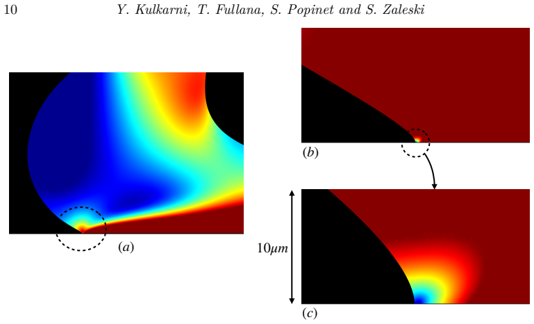
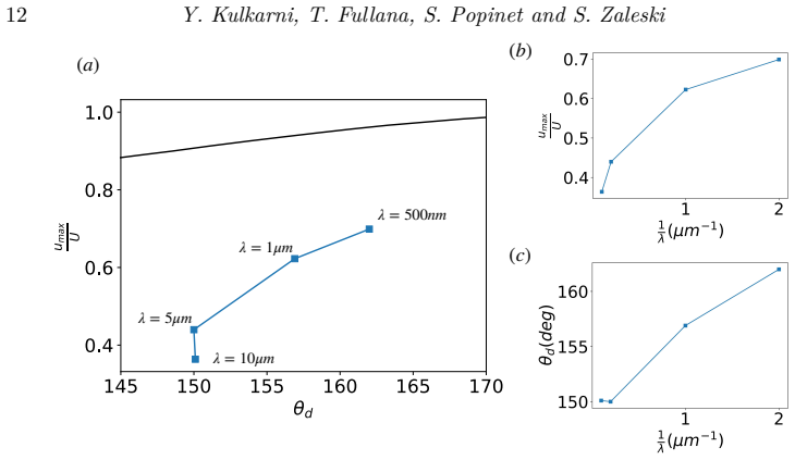
The experimentally reported acceleration of fluid velocity along the interface as the contact line is approached is reproduced by Navier slip models when the local flow outside the slip region is described by an inertially corrected wedge solution. Curtain coating at Ca ~ O(1) yields local Re ~ O(1) based on distances of tens of micrometers, so inertia governs the observable microscale region. Simulations confirm that qualitative microscale observations therefore do not rule out slip models for advancing contact lines.
What carries the argument
Navier slip boundary condition together with an inertially corrected wedge flow solution whose wedge angle is fixed by the macroscopic inflection-point contact angle.
If this is right
- The critical capillary number for wetting failure varies non-monotonically with global Reynolds number.
- The macroscopic contact angle at the inflection point changes with Reynolds number in agreement with experiment.
- At scales larger than the microscale region the interface shape follows the Benney solution.
- Agreement between the inertially corrected wedge solution and the simulated interface velocity improves as the slip length is reduced.
Where Pith is reading between the lines
- Similar inertial corrections outside the slip zone may apply to other high-speed coating flows that involve advancing contact lines.
- Varying the slip length in controlled experiments could reveal the transition from wedge-like to slip-dominated behavior.
- Pure Stokes-flow models are likely insufficient for describing the observable microscale region when Ca is order one.
- The framework could be extended to test predictions for unsteady contact-line motion or the onset of air entrainment.
Load-bearing premise
That a fixed microscopic contact angle plus the inertially corrected wedge solution remain accurate descriptors in the microscale region outside the slip zone, provided the slip length is sufficiently small relative to that region.
What would settle it
Direct measurement or simulation of interfacial velocity at scales comparable to or smaller than the slip length showing systematic deviation from the inertially corrected wedge solution while still obeying the global trends in critical capillary number.
Figures


read the original abstract
Curtain coating, in which a moving plate is coated by a falling liquid sheet, sustains advancing contact lines at large capillary numbers Ca ~ O(1), based on plate speed. Steady states exist up to a critical capillary number, beyond which wetting failure occurs through air-bubble entrainment. In the steady regime, experiments report that velocity along the fluid-fluid interface accelerates as the contact line is approached, down to tens of micrometres; this has been interpreted as evidence against the Navier slip model. We ask whether this acceleration is compatible with slip models, and show that it is. Although Navier slip implies a vanishing velocity at the contact line, the experimentally accessible microscale region lies outside the slip region. The curtain-coating setup is revealing because the local Reynolds number, based on distance from the contact line r ~ 10 microns, is order unity, so the observable flow is governed by local inertia. Our two-phase Navier-Stokes Volume-of-Fluid simulations with quadtree adaptive mesh refinement resolve the smallest scales and study the flow with a Navier slip boundary condition and fixed contact angle. The simulations reproduce the non-monotonic dependence of the critical capillary number on global Reynolds number, based on feed-flow velocity, and the variation of the macroscopic contact angle at the inflection point, in agreement with Liu et al (2016). The interfacial velocity in the microscale region is well described by an inertially corrected wedge flow solution whose wedge angle is set by the inflection-point value, with agreement improving as slip length is reduced; at larger scales, interface bending follows the Benney solution. These inertial effects, absent from pure Stokes flow, are essential in the experimental region. Thus qualitative microscale observations do not decisively invalidate slip models for advancing contact lines.
Editorial analysis
A structured set of objections, weighed in public.
Referee Report
Summary. The paper claims that microscale interfacial velocity acceleration observed in curtain-coating advancing contact lines (r ~ 10 μm) is compatible with Navier slip models. Although slip enforces zero velocity at the contact line, the experimentally accessible region lies outside the slip zone; there local Reynolds number is O(1), so inertially corrected wedge flow (with wedge angle set by the inflection-point macroscopic angle) governs the observable dynamics. Two-phase Navier-Stokes VOF simulations with quadtree AMR, Navier slip, and fixed microscopic contact angle reproduce the non-monotonic critical Ca versus global Re dependence and the inflection-point angle variation reported by Liu et al. (2016). Interface velocity in the microscale region matches the inertially corrected wedge solution (improving as slip length decreases), while larger-scale bending follows the Benney solution. The conclusion is that qualitative microscale observations do not invalidate slip models.
Significance. If the numerical results hold, the work resolves an apparent contradiction between slip models and microscale experiments by showing that local inertia (absent in Stokes analyses) accounts for the observed acceleration once the observable region is outside the slip zone. It strengthens the physical basis for Navier slip in dynamic wetting at Ca ~ O(1) and highlights the necessity of scale separation plus inertia in modeling coating flows. Strengths include direct reproduction of two independent experimental trends from Liu et al. (2016), quantitative comparison to an independent analytic wedge solution, and use of adaptive mesh refinement to resolve the relevant microscales.
major comments (2)
- [Numerical results and comparison to wedge solution] The central claim requires that the chosen slip length remains sufficiently small relative to the 10 μm observable region so that the microscale flow is accurately described by the inertially corrected wedge solution outside the slip zone. No explicit values of the slip length, no quantitative bound demonstrating slip length ≪ 10 μm, and no sensitivity plots of velocity profiles versus slip length are provided in the results or methods sections; without these the scale-separation argument remains unverified and load-bearing for the compatibility conclusion.
- [Simulation setup and validation] Mesh convergence, resolution in the microscale region, and quantitative error bars on the extracted velocity profiles are not reported. The abstract states that simulations reproduce the non-monotonic Ca-Re trend and inflection-angle variation, but without documented grid-independence tests or residual norms the quantitative match to the inertially corrected wedge solution cannot be assessed at the level needed to support the claim that inertia, rather than slip details, governs the observations.
minor comments (2)
- [Introduction] The distinction between the global Reynolds number (based on feed-flow velocity) and the local Reynolds number (based on distance r from the contact line) should be defined explicitly with symbols and numerical estimates in the introduction or methods.
- [Results] Figure captions and text should clarify the precise location of the inflection point used to set the wedge angle and how it is extracted from the simulated interface shape.
Simulated Author's Rebuttal
We thank the referee for the positive assessment of our work and for the constructive comments that help strengthen the manuscript. We address each major point below and will incorporate the requested clarifications and additional documentation in the revised version.
read point-by-point responses
-
Referee: The central claim requires that the chosen slip length remains sufficiently small relative to the 10 μm observable region so that the microscale flow is accurately described by the inertially corrected wedge solution outside the slip zone. No explicit values of the slip length, no quantitative bound demonstrating slip length ≪ 10 μm, and no sensitivity plots of velocity profiles versus slip length are provided in the results or methods sections; without these the scale-separation argument remains unverified and load-bearing for the compatibility conclusion.
Authors: We agree that explicit documentation of the slip lengths and their relation to the observable scale is necessary to fully substantiate the scale-separation argument. Although the manuscript notes that agreement with the wedge solution improves as slip length is reduced, we did not include the specific values or sensitivity analysis in the submitted version. In the revision we will add: (i) the precise slip lengths used (on the order of 0.1–1 μm), (ii) a quantitative bound confirming slip length ≪ 10 μm (typically < 0.1), and (iii) sensitivity plots of interfacial velocity profiles for several slip lengths demonstrating convergence to the inertially corrected wedge solution. These additions will verify that the microscale acceleration is governed by local inertia outside the slip zone. revision: yes
-
Referee: Mesh convergence, resolution in the microscale region, and quantitative error bars on the extracted velocity profiles are not reported. The abstract states that simulations reproduce the non-monotonic Ca-Re trend and inflection-angle variation, but without documented grid-independence tests or residual norms the quantitative match to the inertially corrected wedge solution cannot be assessed at the level needed to support the claim that inertia, rather than slip details, governs the observations.
Authors: We concur that mesh-convergence documentation and error quantification are required to support the quantitative claims. The submitted manuscript relies on quadtree AMR to resolve microscales but does not present convergence tests or error bars. In the revised version we will include: (i) grid-independence studies with successive refinement levels, (ii) minimum cell sizes achieved in the microscale region relative to the slip length, and (iii) quantitative error norms or bars on the extracted velocity profiles and their deviation from the wedge solution. These will confirm that the reported trends and comparisons are robust and not sensitive to numerical details. revision: yes
Circularity Check
No significant circularity; results from independent simulations validated externally
full rationale
The paper derives its conclusions from direct two-phase Navier-Stokes VOF simulations with adaptive mesh refinement, Navier slip boundary condition, and a fixed microscopic contact angle. These are compared to external experimental data (Liu et al. 2016) for critical capillary number and macroscopic angle, and to an independent analytic inertially corrected wedge solution whose angle is taken from the simulation's inflection point but whose functional form is not fitted to the same data. No load-bearing step reduces a prediction to a fitted parameter from the validation set, nor relies on self-citation chains for uniqueness or ansatz. The derivation chain is self-contained against external benchmarks.
Axiom & Free-Parameter Ledger
free parameters (1)
- slip length
axioms (3)
- standard math Incompressible two-phase Navier-Stokes equations govern the flow
- domain assumption Volume-of-Fluid method with quadtree AMR accurately captures the interface and contact-line region
- domain assumption Microscopic contact angle remains fixed while macroscopic angle varies
Reference graph
Works this paper leans on
-
[1]
Philosophical Transactions of the Royal Society of London , number =
Young, Thomas , title =. Philosophical Transactions of the Royal Society of London , number =. 1805 , month =. doi:10.1098/rstl.1805.0005 , url =
-
[2]
Wetting and spreading , author =. Rev. Mod. Phys. , volume =. 2009 , doi =
2009
-
[3]
Kistler, S. F. , title =
-
[4]
A Cartesian grid embedded boundary method for Poisson's equation on irregular domains , author =. J. Comput. Phys. , year =
-
[5]
Dynamic wetting failure in curtain coating: Comparison of model predictions and experimental observations , author =. Chem. Eng. Sci. , volume =. 2019 , doi =
2019
-
[6]
An atomistic model for the Navier slip condition , author =. J. Fluid Mech. , volume =. 2021 , doi =
2021
-
[7]
Navier, C. L. M. H. , title =. M
-
[8]
and Fullana, T
Kulkarni, Y. and Fullana, T. and Zaleski, S. , title =. Proc. R. Soc. A , volume =. 2023 , doi =
2023
-
[9]
The moving contact line on a smooth solid surface , author =. Int. J. Multiph. Flow , volume =. 1993 , doi =
1993
-
[10]
and Zaleski, S
Chirco, L. and Zaleski, S. , title =. Int. J. Numer. Methods Fluids , volume =. 2023 , doi =
2023
-
[11]
Putting the micro into the macro: A molecularly augmented hydrodynamic model of dynamic wetting applied to flow instabilities during forced dewetting , author =. J. Fluid Mech. , volume =. 2022 , doi =
2022
-
[12]
Nanoscale sheared droplet: Volume-of-fluid, phase-field and no-slip molecular dynamics , author =. J. Fluid Mech. , volume =. 2022 , doi =
2022
-
[13]
A variational approach to moving contact line hydrodynamics , author =. J. Fluid Mech. , volume =. 2006 , doi =
2006
-
[14]
Kinetics of liquid--liquid displacement , author =. J. Colloid Interface Sci. , volume =. 1969 , doi =
1969
-
[15]
and Vandre, E
Liu, C.-Y. and Vandre, E. and Carvalho, M. S. and Kumar, S. , title =. J. Fluid Mech. , year =
-
[16]
Rival contact-angle models and the spreading of drops , author =. J. Fluid Mech. , volume =. 1992 , doi =
1992
-
[17]
Dynamic wetting by liquids of different viscosity , author =. J. Colloid Interface Sci. , volume =. 2002 , doi =
2002
-
[18]
Comment on ``Dynamic wetting by liquids of different viscosity'' , author =. J. Colloid Interface Sci. , volume =. 2004 , doi =
2004
-
[19]
Physica D , volume =
Singularities at the moving contact line: Mathematical, physical and computational aspects , author =. Physica D , volume =. 2006 , doi =
2006
-
[20]
and Zaleski, S
Afkhami, S. and Zaleski, S. and Bussmann, M. , journal =. A mesh-dependent model for applying dynamic contact angles to. 2009 , doi =
2009
-
[21]
and Scriven, L
Huh, C. and Scriven, L. E. , title =. J. Colloid Interface Sci. , year =
-
[22]
On the motion of a fluid--fluid interface along a solid surface , author =. J. Fluid Mech. , volume =. 1974 , doi =
1974
-
[23]
The moving contact line: The slip boundary condition , author =. J. Fluid Mech. , volume =. 1976 , doi =
1976
-
[24]
A moving fluid interface. Part 2. The removal of the force singularity by a slip flow , author =. J. Fluid Mech. , volume =. 1977 , doi =
1977
-
[25]
Fluid Dyn
Hydrodynamics of wetting , author =. Fluid Dyn. , volume =. 1976 , doi =
1976
-
[26]
The dynamics of the spreading of liquids on a solid surface. Part 1. Viscous flow , author =. J. Fluid Mech. , volume =. 1986 , doi =
1986
-
[27]
Physica D , volume =
A kinematic evolution equation for the dynamic contact angle and some consequences , author =. Physica D , volume =. 2019 , doi =
2019
-
[28]
Meniscus draw-up and draining , author =. Eur. J. Appl. Math. , volume =. 2001 , doi =
2001
-
[29]
Forced dewetting on porous media , author =. J. Fluid Mech. , volume =. 2007 , doi =
2007
-
[30]
Weinstein, S. J. and Ruschak, K. J. , title =. Annu. Rev. Fluid Mech. , volume =. 2004 , doi =
2004
-
[31]
Characteristics of air entrainment during dynamic wetting failure along a planar substrate , author =. J. Fluid Mech. , volume =. 2014 , doi =
2014
-
[32]
Blake, T. D. and Bracke, M. and Shikhmurzaev, Y. D. , title =. Phys. Fluids , volume =. 1999 , doi =
1999
-
[33]
, title =
Clarke, A. , title =. Chem. Eng. Sci. , volume =. 1995 , doi =
1995
-
[34]
Dynamic drying transition via free-surface cusps , author =. J. Fluid Mech. , volume =. 2019 , doi =
2019
-
[35]
Cox--Voinov theory with slip , author =. J. Fluid Mech. , volume =. 2020 , doi =
2020
-
[36]
Nonlocal hydrodynamic influence on the dynamic contact angle: Slip models versus experiment , author =. Phys. Rev. E , volume =. 2006 , doi =
2006
-
[37]
Inertial effects on the flow near a moving contact line , author =. J. Fluid Mech. , volume =. 2021 , doi =
2021
-
[38]
and Bussmann, M
Afkhami, S. and Bussmann, M. , title =. Int. J. Numer. Methods Fluids , volume =. 2008 , doi =
2008
-
[39]
and Bussmann, M
Afkhami, S. and Bussmann, M. , title =. Int. J. Numer. Methods Fluids , volume =. 2009 , doi =
2009
-
[40]
, title =
Popinet, S. , title =. J. Comput. Phys. , year =
-
[41]
, title =
Popinet, S. , title =. Annu. Rev. Fluid Mech. , year =
-
[42]
and Zaleski, S
Scardovelli, R. and Zaleski, S. , title =. Annu. Rev. Fluid Mech. , year =
-
[43]
and Zaleski, S
Popinet, S. and Zaleski, S. , title =. Int. J. Numer. Methods Fluids , year =
-
[44]
and Buongiorno, J
Afkhami, S. and Buongiorno, J. and Guion, A. and Popinet, S. and Saade, Y. and Scardovelli, R. and Zaleski, S. , title =. J. Comput. Phys. , year =
-
[45]
and Zaleski, S
Fullana, T. and Zaleski, S. and Popinet, S. , title =. Eur. Phys. J. Spec. Top. , year =
-
[46]
and Johansson, P
Lācis, U. and Johansson, P. and Fullana, T. and Hess, B. and Amberg, G. and Bagheri, S. and Zaleski, S. , title =. Eur. Phys. J. Spec. Top. , year =
-
[47]
Hirt, C. W. and Nichols, B. D. , title =. J. Comput. Phys. , volume =. 1981 , doi =
1981
-
[48]
and Scardovelli, R
Tryggvason, G. and Scardovelli, R. and Zaleski, S. , title =. 2011 , doi =
2011
-
[49]
A second-order projection method for the incompressible Navier--Stokes equations , author =. J. Comput. Phys. , volume =. 1989 , doi =
1989
-
[50]
, journal =
Popinet, S. , journal =. Gerris: A tree-based adaptive solver for the incompressible. 2003 , doi =
2003
-
[51]
Benney, D. J. and Timson, W. J. , title =. Stud. Appl. Math. , volume =. 1980 , doi =
1980
-
[52]
Ngan, C. G. and Dussan V., E. B. , title =. Phys. Fluids , volume =. 1984 , doi =
1984
-
[53]
Benilov, E. S. and Vynnycky, M. , journal =. Contact lines with a 180^. 2013 , doi =
2013
-
[54]
Viscous and resistive eddies near a sharp corner , author =. J. Fluid Mech. , volume =. 1964 , doi =
1964
discussion (0)
Sign in with ORCID, Apple, or X to comment. Anyone can read and Pith papers without signing in.