Recognition: 3 theorem links
· Lean TheoremYinsen: A low power density HTS tokamak fusion reactor for marine and off-grid applications
Pith reviewed 2026-05-08 18:17 UTC · model grok-4.3
The pith
An HTS tokamak limited to 0.7 MW per square meter fusion power density can deliver more than 25 MWe net for marine and off-grid uses.
A machine-rendered reading of the paper's core claim, the machinery that carries it, and where it could break.
Core claim
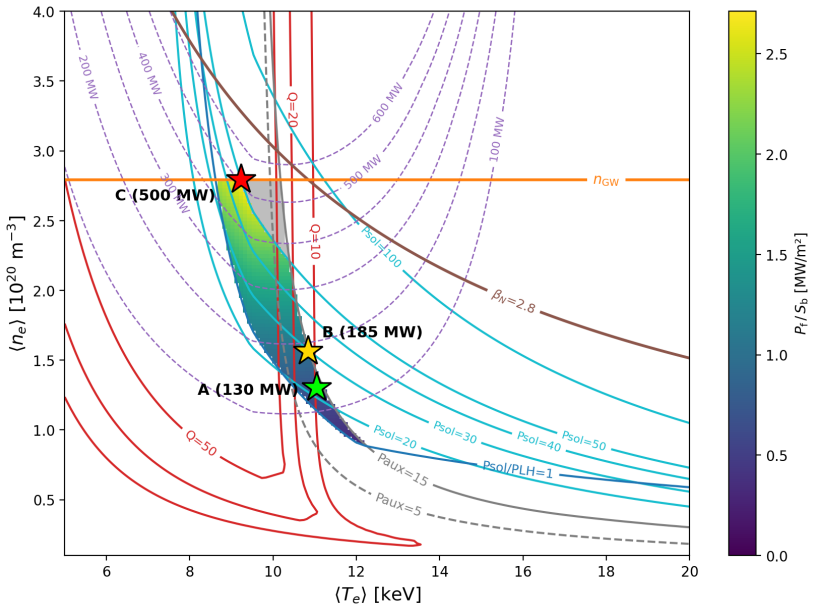
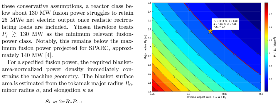
By anchoring the entire reactor design to a materials-limited fusion power density of 0.7 MW per square meter, obtained from the 35 DPA structural limit on V-4Cr-4Ti with a 20-year lifetime, 40 percent utilization, and geometric correction, a self-consistent high-temperature-superconducting tokamak emerges with 130 MW fusion power, a shaped 9.29 T plasma at 9.67 MA, tritium breeding ratio of approximately 1.1, and net electric output above 25 MWe, suitable for maritime and remote applications.
What carries the argument
The materials-limited fusion power density of 0.7 MW per square meter, derived from the 35 DPA limit on the V-4Cr-4Ti vacuum vessel together with lifetime, utilization, and geometric factors, which fixes the minimum useful reactor size and enables the remaining high-field HTS, transport, divertor, and neutronics design points.
If this is right
- The vacuum vessel reaches a lifetime of 1040 MW·yr, supporting the full 20-year plant life at 130 MW fusion power.
- Total nuclear heating in the toroidal-field HTS magnets is only 7.4 kW at 20 K, allowing them to remain lifetime components across many vacuum-vessel replacements.
- Neon-seeded detached divertor operation reduces peak heat fluxes well below 10 MW per square meter.
- A supercritical CO₂ balance of plant combined with a 34 kV medium-voltage backbone and local energy storage supports pulsed operation.
- Several technical challenges that lie between Q greater than 1 and competitive grid-scale economics are avoided in this lower-density regime.
Where Pith is reading between the lines
- A reactor of this type could reach first commercial deployment in niche markets such as large vessels or isolated industrial sites well before full grid economics are solved.
- The same materials-limited sizing logic could be applied to other fusion concepts to shorten the path from laboratory results to useful power.
- Further increases in net output within the same power-density ceiling could be achieved by enlarging plasma volume or raising thermal-to-electric conversion efficiency.
- Dedicated experiments that measure actual plasma performance and neutron damage rates at the modeled conditions would directly test whether the operating window remains accessible.
Load-bearing premise
The 0.7 MW per square meter power density limit derived from the 35 DPA damage threshold on the vanadium alloy accurately represents the reactor's structural endurance under the assumed lifetime and utilization without requiring higher densities for practical output.
What would settle it
A neutron irradiation test on V-4Cr-4Ti samples that reaches the 35 DPA damage limit in less than the modeled equivalent operating time at the baseline power, or an experimental plasma discharge that cannot meet the required confinement and stability at 9.29 T and 9.67 MA while keeping divertor heat fluxes below 10 MW per square meter.
Figures


read the original abstract
Yinsen is a high-temperature-superconducting (HTS) tokamak reactor concept for off-grid applications such as maritime propulsion, remote power, and industrial energy. Rather than pursuing grid-scale power density, the design is anchored to a materials-limited fusion power density of $P_f/S_b=0.7~\mathrm{MW/m^2}$, obtained from a 35 DPA structural limit, a 20-year plant lifetime, 40% utilization, and a geometric damage-peaking correction. The resulting device has a V-4Cr-4Ti vacuum-vessel lifetime of $1040~\mathrm{MW\cdot yr}$, pointing to a minimum useful fusion power of $130~\mathrm{MW}$ and more than $25~\mathrm{MWe}$ net output. Integrated FUSE modeling refines the design into a self-consistent high-field baseline with a shaped 9.29 T, 9.67 MA plasma, while ASTRA transport analysis corroborates a broader operating window above the minimum design point. Divertor power handling is addressed with UEDGE modeling, showing that impurity-seeded detached operation is attainable with neon seeding, reducing peak heat fluxes well below $10~\mathrm{MW/m^2}$. OpenMC neutronics calculations with a double-layered WC/W$_2$B$_5$ shield show that the vacuum vessel is the lifetime-limiting solid structure, while the HTS magnets remain lifetime components: at the 130 MW baseline, total TF nuclear heating is 7.4 kW at 20 K, and the TF fast-neutron limit corresponds to roughly sixteen vacuum-vessel lifetimes. The same neutronics analysis gives $TBR\approx1.1$ with 30% $^6\mathrm{Li}$ enrichment and no dedicated neutron multiplier. Plant-level studies detail a supercritical CO$_2$ balance of plant and pulsed-power operation using a 34 kV medium-voltage backbone and local energy storage. Taken together, these results suggest that a low-power-density HTS tokamak offers a near-term path for relevant FOAK fusion reactors where many remaining challenges between $Q>1$ and economic grid operation are alleviated.
Editorial analysis
A structured set of objections, weighed in public.
Referee Report
Summary. The manuscript presents a conceptual design for Yinsen, a high-temperature superconducting (HTS) tokamak fusion reactor for off-grid and marine applications. It is anchored to a materials-limited fusion power density of 0.7 MW/m² derived from a 35 DPA limit on V-4Cr-4Ti vacuum vessel material, 20-year lifetime, 40% utilization, and geometric peaking correction, yielding a minimum useful fusion power of 130 MW with >25 MWe net output. Integrated modeling with FUSE establishes a self-consistent high-field baseline (9.29 T, 9.67 MA), ASTRA confirms a broader operating window, UEDGE demonstrates neon-seeded detached divertor operation with heat fluxes <10 MW/m², and OpenMC neutronics yields TBR≈1.1 with WC/W₂B₅ shielding while showing HTS magnets as lifetime components. Plant-level analysis covers supercritical CO₂ balance of plant and pulsed-power systems. The authors conclude this low-power-density approach offers a near-term path to first-of-a-kind fusion reactors by alleviating challenges between Q>1 and economic grid operation.
Significance. If the materials-limited power density and modeling fidelity hold, the work has moderate significance as an exploration of an alternative fusion design space that prioritizes earlier deployment for niche applications over grid-scale power density. The explicit linkage of structural lifetime assumptions to device scale, combined with multi-code integration (FUSE, ASTRA, UEDGE, OpenMC) for a consistent baseline, provides a useful reference for systems-level studies. It highlights how HTS enables high-field operation at reduced densities, potentially simplifying some power-handling and lifetime issues. The absence of experimental validation for the codes in this regime and the assumption-driven nature of the central scale limit the broader impact.
major comments (3)
- [Introduction / Design philosophy] Introduction and design philosophy section: The 0.7 MW/m² fusion power density limit is obtained from a 35 DPA structural limit on V-4Cr-4Ti, 20-year lifetime, 40% utilization, and geometric damage-peaking correction, directly setting the minimum 130 MW fusion power. No sensitivity analysis is provided for variations in these inputs (e.g., 30 DPA or 30% utilization), and no experimental benchmarks for the DPA-to-power-density conversion under fusion spectra are cited; this assumption is load-bearing for the entire minimum-size claim and the 'near-term path' assertion.
- [FUSE / ASTRA sections] FUSE and ASTRA modeling sections: The self-consistent baseline (9.29 T, 9.67 MA) and broader operating window are derived from these codes without any comparison to experimental tokamak data in the high-field low-density regime or uncertainty quantification on transport assumptions. If the predicted performance deviates, both the claimed operating window and the assertion that many challenges between Q>1 and economic operation are alleviated are affected.
- [UEDGE / OpenMC sections] UEDGE and OpenMC sections: Detached operation is shown with neon seeding reducing peak heat fluxes below 10 MW/m², and TBR≈1.1 is reported with 30% ⁶Li enrichment, but the specific impurity concentrations, their impact on core performance or TBR, and sensitivity of neutronics results (including the claim that TF magnets correspond to sixteen vacuum-vessel lifetimes) lack quantification or error bars. These are load-bearing for the feasibility and lifetime conclusions.
minor comments (3)
- All acronyms (TBR, DPA, HTS, FOAK, sCO₂) should be defined at first use for clarity.
- Add explicit references to prior experimental or modeling benchmarks for the FUSE, ASTRA, UEDGE, and OpenMC codes in relevant parameter regimes.
- Include a table summarizing key parameters (B_t, I_p, P_f, TBR, heat fluxes) with uncertainty ranges where available.
Simulated Author's Rebuttal
We thank the referee for their constructive comments on our manuscript describing the Yinsen low-power-density HTS tokamak concept. We have carefully considered each major comment and provide point-by-point responses below. Where the comments identify opportunities to strengthen the analysis, we will incorporate revisions in the updated manuscript.
read point-by-point responses
-
Referee: Introduction and design philosophy section: The 0.7 MW/m² fusion power density limit is obtained from a 35 DPA structural limit on V-4Cr-4Ti, 20-year lifetime, 40% utilization, and geometric damage-peaking correction, directly setting the minimum 130 MW fusion power. No sensitivity analysis is provided for variations in these inputs (e.g., 30 DPA or 30% utilization), and no experimental benchmarks for the DPA-to-power-density conversion under fusion spectra are cited; this assumption is load-bearing for the entire minimum-size claim and the 'near-term path' assertion.
Authors: We agree that sensitivity analysis on the key assumptions would improve the robustness of the minimum-size claim. In the revised manuscript, we will add a dedicated subsection or appendix presenting sensitivity studies varying the DPA limit (30-40), utilization (30-50%), and lifetime, showing the resulting range in minimum fusion power (approximately 100-160 MW). For the DPA-to-power-density conversion, we will cite additional references on vanadium alloy irradiation data under fission and fusion-relevant spectra, noting that the 35 DPA limit is a conservative engineering value from the literature. While direct long-term experimental benchmarks in a true fusion neutron spectrum are not yet available, the methodology aligns with standard practices in fusion reactor design studies. We will also clarify the geometric peaking correction derivation. revision: yes
-
Referee: FUSE and ASTRA modeling sections: The self-consistent baseline (9.29 T, 9.67 MA) and broader operating window are derived from these codes without any comparison to experimental tokamak data in the high-field low-density regime or uncertainty quantification on transport assumptions. If the predicted performance deviates, both the claimed operating window and the assertion that many challenges between Q>1 and economic operation are alleviated are affected.
Authors: The high-field low-density operating space is an extrapolation beyond current experimental databases, which is inherent to exploring HTS-enabled designs. FUSE incorporates empirical scalings from existing tokamaks, and we will add explicit comparisons to the ITER98(y,2) scaling law and other high-field projections in the revised text. For ASTRA, we will include a discussion of transport model uncertainties by varying the anomalous transport coefficients within ranges consistent with existing data and showing the impact on the Q and power balance. A new figure will illustrate the operating window with uncertainty bands derived from these variations. This will support the claim that the design alleviates certain challenges while acknowledging the modeling limitations. revision: partial
-
Referee: UEDGE and OpenMC sections: Detached operation is shown with neon seeding reducing peak heat fluxes below 10 MW/m², and TBR≈1.1 is reported with 30% ⁶Li enrichment, but the specific impurity concentrations, their impact on core performance or TBR, and sensitivity of neutronics results (including the claim that TF magnets correspond to sixteen vacuum-vessel lifetimes) lack quantification or error bars. These are load-bearing for the feasibility and lifetime conclusions.
Authors: We will enhance the UEDGE section with the specific neon concentration (approximately 1.5% in the scrape-off layer for the detached case) and couple it to ASTRA to quantify any degradation in core confinement or fusion power. For OpenMC neutronics, we will report Monte Carlo statistical uncertainties on TBR (typically ±0.01) and provide sensitivity curves for TBR versus ⁶Li enrichment and shield thickness. The TF magnet lifetime claim will be backed by explicit dpa and fast neutron fluence values, with a note that the sixteen-fold margin is based on the conservative fast-neutron limit for REBCO. Additional text will address potential impacts of impurities on TBR. revision: yes
- The complete experimental validation of integrated modeling in the high-field, low-density regime cannot be provided, as no tokamak has yet operated in this parameter space.
Circularity Check
Minimum useful fusion power of 130 MW and 0.7 MW/m² density limit follow directly by arithmetic from the 35 DPA, 20 yr, 40% utilization and geometric correction inputs
specific steps
-
self definitional
[Abstract]
"the design is anchored to a materials-limited fusion power density of P_f/S_b=0.7 MW/m², obtained from a 35 DPA structural limit, a 20-year plant lifetime, 40% utilization, and a geometric damage-peaking correction. The resulting device has a V-4Cr-4Ti vacuum-vessel lifetime of 1040 MW·yr, pointing to a minimum useful fusion power of 130 MW and more than 25 MWe net output."
The 0.7 MW/m² value is defined from the listed assumptions; the 1040 MW·yr is the total fusion energy the vessel can sustain before 35 DPA; dividing by the assumed operating time (20 yr × 0.4) yields exactly 130 MW. The 'minimum useful' power is therefore the arithmetic consequence of the inputs, not an independent result.
full rationale
The paper fixes the central scale (power density and minimum power) by explicit construction from material lifetime assumptions rather than from an independent external benchmark or first-principles derivation. The subsequent modeling (FUSE, ASTRA, UEDGE, OpenMC) is performed on a device whose size and power are already set by those same assumptions, so the claim that this configuration 'offers a near-term path' inherits the definitional scaling. No self-citation chain or renamed known result is present; the circularity is limited to this one load-bearing definitional step.
Axiom & Free-Parameter Ledger
free parameters (2)
- Fusion power density limit =
0.7 MW/m²
- Vacuum vessel lifetime =
1040 MW·yr
axioms (2)
- domain assumption V-4Cr-4Ti vacuum vessel can operate to 35 DPA before replacement
- domain assumption Standard tokamak transport and divertor physics models in ASTRA and UEDGE apply without major modification
Lean theorems connected to this paper
-
Constants/RSUnitsHelpers (no overlap)n/a unclear?
unclearRelation between the paper passage and the cited Recognition theorem.
Pf = C(T) β^2 B^4 V, C(T) ≡ E_f ⟨σv⟩/(64 μ0^2 T^2)
What do these tags mean?
- matches
- The paper's claim is directly supported by a theorem in the formal canon.
- supports
- The theorem supports part of the paper's argument, but the paper may add assumptions or extra steps.
- extends
- The paper goes beyond the formal theorem; the theorem is a base layer rather than the whole result.
- uses
- The paper appears to rely on the theorem as machinery.
- contradicts
- The paper's claim conflicts with a theorem or certificate in the canon.
- unclear
- Pith found a possible connection, but the passage is too broad, indirect, or ambiguous to say the theorem truly supports the claim.
Reference graph
Works this paper leans on
-
[1]
R. J. Hawryluk, Results from deuterium– tritium tokamak confinement experiments, Rev. Mod. Phys. 70 (1998) 537–587
1998
-
[2]
Keilhacker et al, High fusion performance from deuterium–tritium plasmas in JET, Nucl
M. Keilhacker et al, High fusion performance from deuterium–tritium plasmas in JET, Nucl. Fusion 39 (1999) 209–234
1999
-
[3]
Abu-Shawareb et al, Achievement of ignition in a laboratory fusion experiment, Phys
H. Abu-Shawareb et al, Achievement of ignition in a laboratory fusion experiment, Phys. Rev. Lett. 132 (2024) 065102
2024
-
[4]
A. J. Creely et al, Overview of the SPARC toka- mak, J. Plasma Phys. 86 (2020) 865860502
2020
-
[5]
Online ITER overview available from the IAEA Fusion Energy Conference 2001 materials
International Atomic Energy Agency, Interna- tional Organizations — ITER, 2001. Online ITER overview available from the IAEA Fusion Energy Conference 2001 materials
2001
-
[6]
Whyte, Fusion economics: power den- sity, materials and maintenance, September 12, 2024
D. Whyte, Fusion economics: power den- sity, materials and maintenance, September 12, 2024
2024
-
[7]
nuclear generat- ing statistics, accessed April 4, 2026
Nuclear Energy Institute, U.S. nuclear generat- ing statistics, accessed April 4, 2026
2026
-
[8]
Commander, Navy Region Mid-Atlantic, His- tory, Naval Submarine Base New London, not- ing USSNautilusas the world’s first nuclear- powered submarine, accessed April 4, 2026
2026
-
[9]
Department of Energy, December 23, 1957: Shippingport, Office of History and Her- itage Resources, accessed April 4, 2026
U.S. Department of Energy, December 23, 1957: Shippingport, Office of History and Her- itage Resources, accessed April 4, 2026
1957
-
[10]
D. Pettinari, S. Meschini, and R. Testoni, As- sessment of structural materials in compact fu- sion reactor design, Front. Nucl. Eng. 4 (2025) 1683702. doi:10.3389/fnuen.2025.1683702
-
[11]
A. F. Rowcliffe and G. Burn,Fusion Mate- rials Semiannual Progress Report for Period Ending December 31, 1998, DOE/ER-0313/25, ORNL/M-6712, Oak Ridge National Labora- tory, April 1999. doi:10.2172/6717
-
[12]
H. M. Chung, B. A. Loomis, and D. L. Smith, Properties of V–4Cr–4Ti for application as fusion reactor structural components, Fusion Eng. Des. 29 (1995) 455–464. doi:10.1016/0920- 3796(95)80053-Z
-
[13]
H. M. Chung, A. P. Tsai, D. L. Smith, L. J. Nowicki, D. L. Rink, and R. V. Strain, Mi- crostructural evolution of V–4Cr–4Ti during neutron irradiation at 390–600 ◦C to 24–34 dpa, U.S./Japan collaborative irradiation stud- ies technical report, ANL/FPP/TM-286, 1995. doi:10.2172/415186
-
[14]
D. P. Butt, X. Hu, C. H. Skinner, T. Muroga, T. Nagasaka, N. Baluc, and R. L¨ asser, Research and development on vana- dium alloys for fusion breeder blanket appli- cation, Fusion Eng. Des. 210 (2025) 114739. doi:10.1016/j.fusengdes.2024.114739
-
[15]
A. C. Rolfe, P. Brown, P. Carteret al., A re- port on the first remote handling operations at JET, Fusion Eng. Des. 46 (1999) 299–306. doi:10.1016/S0920-3796(99)00022-8
-
[16]
Blanchard, J
W. Blanchard, J. Bartlit, R. Bellet al., Tritium processing and management during D–T exper- iments on TFTR, OSTI record 41436, 1995
1995
-
[17]
Wenninger et al, The physics and technology basis entering European system code studies for DEMO, Nucl
R. Wenninger et al, The physics and technology basis entering European system code studies for DEMO, Nucl. Fusion 57 (2017) 016011
2017
-
[18]
Kuang et al (2018), Fus
A.Q. Kuang et al (2018), Fus. Eng. and Design, 137, p. 221-242
2018
-
[19]
Stambaugh, L
R. Stambaugh, L. Lao, and E. Lazarus, Re- lation of vertical stability and aspect ratio in tokamaks, Nucl. Fusion 32 (9) (1992) 1642
1992
-
[20]
U. Plank, R. M. McDermott, G. Birkenmeier, N. Bonanomi, M. Cavedon, G. D. Conway, T. Eich, M. Griener, O. Grover, P. A. Schneider, M. Willensdorfer, et al., Overview of L- to H- mode transition experiments at ASDEX Up- grade, Plasma Phys. Control. Fusion 65 (2023) 014001. doi:10.1088/1361-6587/aca35b
-
[21]
C. Hansen, I. G. Stewart, D. Burgess, M. Pharr, S. Guizzo, F. Logak, A. O. Nelson, and C. Paz-Soldan, TokaMaker: An open-source time- dependent Grad-Shafranov tool for the design and modeling of axisymmetric fusion devices, Comput. Phys. Commun. 298 (2024) 109111. doi:10.1016/j.cpc.2024.109111
-
[22]
N. Leuthold, N. C. Logan, D. A. Burgess, A. O. Nelson, S. Benjamin, C. Hansen, A. Kumar, C. F. B. Zimmermann, F. Carpanese, A. J. Creely, J. C. Hillesheim, M. Muraca, and C. Paz-Soldan, ARC physics basis– 69 magnetohydrodynamics, J. Plasma Phys. 92 (2026) E49. doi:10.1017/S0022377826101421
-
[23]
S. Guizzo, M. A. Drabinskiy, C. Hansen, A. G. Kachkin, E. N. Khairutdinov, A. O. Nelson, M. R. Nurgaliev, M. Pharr, G. F. Subbotin, and C. Paz-Soldan, Electromagnetic system conceptual design for a negative triangularity tokamak, Fusion Eng. Des. 219 (2025) 115257. doi:10.1016/j.fusengdes.2025.115257
-
[24]
D. A. Humphreys, T. A. Casper, N. Eidietis, M. Ferrara, D. A. Gates, I. H. Hutchinson, G. L. Jackson, E. Kolemen, J. A. Leuer, J. Lister, L. L. LoDestro, W. H. Meyer, L. D. Pearlstein, A. Portone, F. Sartori, M. L. Walker, A. S. We- lander, and S. M. Wolfe, Experimental vertical stability studies for ITER performance and de- sign guidance, Nucl. Fusion 49...
-
[25]
A. O. Nelson, A. Hyatt, W. Wehner, A. We- lander, C. Paz-Soldan, T. Osborne, H. Anand, and K. E. Thome, Vertical control of DIII-D discharges with strong negative triangularity, Plasma Phys. Control. Fusion 65 (2023) 044002. doi:10.1088/1361-6587/acbe65
-
[26]
S. Guizzo, A. O. Nelson, C. Hansen, F. Lo- gak, and C. Paz-Soldan, Assessment of vertical stability for negative triangularity pilot plants, Plasma Phys. Control. Fusion 66 (2024) 065018. doi:10.1088/1361-6587/ad4175
-
[28]
Neiser, O
T. Neiser, O. Meneghini, T. Slendebroek, S. Smith, J. McClenaghan, A. Ghiozzi, B. Patel, A. Nelson, G. Avdeeva, C. Roach, et al., Large database validation of TGLF on DIII-D and MAST-U plasmas, Bull. Am. Phys. Soc. (2024)
2024
-
[29]
Pereverzev and P
G. Pereverzev and P. N. Yushmanov (2002), ASTRA Automated System for TRansport Analysis in a Tokamak, MPI for Plasma Physics, Garching, Germany, https://pure.mpg.de/rest/items/item_ 2138238/component/file_2138237/content
2002
-
[30]
E. Fableet al.(2013), Novel free-boundary equilibrium and transport solver with theory- based models and its validation against ASDEX Upgrade current ramp scenarios, Plasma Phys. Control. Fusion 55(12) 124028,https://dx. doi.org/10.1088/0741-3335/55/12/124028
-
[31]
G. M. Staebler, J. E. Kinsey and R. E. Waltz (2007), A theory-based transport model with comprehensive physics, Physics of Plasmas 14(5) 055909,https://doi.org/10.1063/1. 2436852
work page doi:10.1063/1 2007
-
[32]
T. Eich, T. Body, M. Faitsch, O. Grover, M. A. Miller, P. Manz, T. Looby, A. Q. Kuang, A. Redl, M. Reinke, A. J. Creely, D. Battaglia, J. Hillesheim, M. Wigram, J. W. Hughes, and the ASDEX Upgrade Team, The separatrix oper- ational space of next-step fusion experiments: From ASDEX Upgrade data to SPARC sce- narios, Nucl. Mater. Energy 42 (2025) 101896. do...
-
[33]
T. Eich, P. Manz, and the ASDEX Upgrade Team, The separatrix operational space of AS- DEX Upgrade due to interchange-drift-Alfv´ en turbulence, Nucl. Fusion 61 (2021) 086017. doi:10.1088/1741-4326/ac0412
-
[34]
M. Faitsch, T. Eich, G. F. Harrer, E. Wolfrum, D. Brida, P. David, M. Dunne, L. Gil, B. Labit, U. Stroth, the EUROfusion MST1 Team, and the ASDEX Upgrade Team, Analysis and ex- pansion of the quasi-continuous exhaust (QCE) regime in ASDEX Upgrade, Nucl. Fusion 63 (2023) 076013. doi:10.1088/1741-4326/acd464
-
[35]
G. F. Harrer, M. Faitsch, L. Radovanovic, E. Wolfrum, C. Albert, A. Cathey, M. Cave- don, M. Dunne, T. Eich, R. Fischer, M. Griener, M. Hoelzl, B. Labit, H. Meyer, F. Aumayr, the ASDEX Upgrade Team, and the EUROfusion MST1 Team, Quasicontin- uous exhaust scenario for a fusion reac- tor: The renaissance of small edge localized modes, Phys. Rev. Lett. 129 (...
-
[36]
O. Meneghini, J. Citrin, M. Boyer, M. Casanova, A. Correa, A. D. Pace, C. D. Challis, 70 S. E. Ferry, A. Janzer, A. M. Jokisaari, G. Man- duchi, T. M. Rognlien, D. T. Farina, N. den Harder, S. H. Hahn, M. Jaeger, F. Imbeaux, D. Kalupin, S. K. Kim, S. Kwon, P. M. Meng, G. Raupp, J. S. Son, R. T. Sbarbaro, J. V. O’Connor, J. L. Varela, F. A. Volpe, M. Wilso...
-
[37]
D. N. Smithe, Finite Larmor radius effects in ion cyclotron resonance heating of inhomo- geneous plasmas, Ph.D. thesis, University of Michigan, 1987
1987
-
[38]
C. Migliore, M. Usoltseva, and J. Wright, Simu- lations of ICRF heating for SPARC during first campaign and primary reference-like discharge using the Stix code, EPJ Web Conf. 346 (2026) 02011. doi:10.1051/epjconf/202634602011
-
[39]
D. N. Smithe, Novel ICRH coupler configura- tion for high-field tokamak, 25th Topical Con- ference on Radio Frequency Power in Plasmas, Hohenkammer, Germany, 2025
2025
-
[40]
S. Moriyama, Y. Ogawa, T. Fujii, K. Anno, S. Shinozaki, M. Terakado, H. Kimura, M. Sai- gusa, T. Nagashima, M. Ohta, D. B. Rem- sen, C. Marshall Loring, S. G. McNees, K. Oi- hara, and T. Yamane, The results of X2242 and X2274 high power tetrodes with the JT- 60 ICRF amplifier in a frequency range of 110– 130 MHz, Fusion Eng. Des. 18 (1992) 237–243. doi:10...
-
[41]
A. D. Maris, A. Wang, C. Rea, R. Granetz, and E. Marmar, The impact of disrup- tions on the economics of a tokamak power plant, Fusion Sci. Technol. 80 (2024) 636–652. doi:10.1080/15361055.2023.2229675
-
[42]
A. M. Wang, C. Rea, O. So, C. Dawson, D. T. Garnier, and C. Fan, Active ramp-down control and trajectory design for tokamaks with neural differential equations and reinforce- ment learning, Commun. Phys. 8 (2025) 231. doi:10.1038/s42005-025-02146-6
-
[43]
N. W. Eidietis, S. P. Gerhardt, R. S. Granetz, Y. Kawano, M. Lehnen, J. B. Lister, G. Pau- tasso, V. Riccardo, R. L. Tanna, A. J. Thorn- ton, and the ITPA Disruption Database Par- ticipants, The ITPA disruption database, Nucl. Fusion 55 (2015) 063030. doi:10.1088/0029- 5515/55/6/063030
-
[44]
Eich et al 2020 Nucl
T. Eich et al 2020 Nucl. Fusion 60 056016
2020
-
[45]
Brunner et al 2018 Nucl
D. Brunner et al 2018 Nucl. Fusion 58 094002
2018
-
[46]
Sorbom, A
B. Sorbom, A. Q. Creely, and C. Tse, Recent developments in the design of ARC, 62nd An- nual Meeting of the APS Division of Plasma Physics (2020)
2020
-
[47]
R. A. Pitts, X. Bonnin, P. Escourbiac, H. Frerichs, J. Gunn, T. Hirai, A. Kukushkin, S. Lisgo, M. Loarte, M. Merola, A. S. Naik, R. Neu, T. Eich, W. Fundamenski, A. Loarte, D. Mou, B. Sieglin, and D. Reiter, Physics basis for the first ITER tungsten diver- tor, Nucl. Mater. Energy 20 (2019) 100696. doi:10.1016/j.nme.2019.100696
-
[50]
J. Li, J. Li, H. Liu, J. Qian, X. Huang, T. Luo, Q. Wang, G. Chen, P. Hu, Y. Lu, and S. Zhang, Optimization design for plasma configuration at the CFETR, Fusion Eng. Des. 152 (2020) 111447. doi:10.1016/j.fusengdes.2019.111447
-
[52]
Rognlien et al, J
T.D. Rognlien et al, J. Nucl. Mater., v. 196-198, 71 p. 347, 1992
1992
-
[53]
Hulse, Nuclear Technology - Fusion 1983,3,259-272
R.A. Hulse, Nuclear Technology - Fusion 1983,3,259-272
1983
-
[54]
Post, Journal of Nuclear Materials 1995,220-222,143-157
D.E. Post, Journal of Nuclear Materials 1995,220-222,143-157
1995
-
[55]
Wang et al., Nucl
H.Q. Wang et al., Nucl. Mater. Energy, v. 33, 2022, 101301
2022
-
[56]
Hydrogenic fast-ion diagnostic using Balmer-alpha light
A. Kallenbach, Impurity seeding for toka- mak power exhaust: from present devices via ITER to DEMO, Plasma Phys. Control. Fusion 55 (2013) 124041. doi:10.1088/0741- 3335/55/12/124041
-
[57]
Wigram et al 2019 Nucl
M.R.K. Wigram et al 2019 Nucl. Fusion 59 106052
2019
-
[58]
J. D. Lore et al 2024 Nucl. Fusion 64 126054
2024
-
[59]
Gong et al 2024 Nucl
X. Gong et al 2024 Nucl. Fusion 64 112013
2024
-
[60]
ITER Organization, IIS PFC design note, educational materials PDF available from the ITER public materials repository, accessed April 2026.https://www.iter.org/sites/ default/files/education/%5B4-3%5D1901% 20IIS%20PFC%20Ezato.pdf
2026
-
[61]
K. Tsuchida, T. Miyazawa, A. Hasegawa, S. Nogami, and M. Fukuda, Recrystallization be- havior of hot-rolled pure tungsten and its alloy plates during high-temperature anneal- ing, Nucl. Mater. Energy 15 (2018) 158–163. doi:10.1016/j.nme.2018.04.004
-
[62]
Robinson Research Institute, Victoria Univer- sity of Wellington, HTS tape database at 20 K, including the Faraday Factory and Shang- hai Superconductor angle-dependence datasets used in this work; local dataset archive accessed April 2026
2026
-
[63]
Bocci et al (2020), Fus
M. Bocci et al (2020), Fus. Eng. and Design, 154, 111529
2020
-
[64]
Muroga et al (2002), J
T. Muroga et al (2002), J. Nucl. Mater., 307– 311, p. 547–554
2002
-
[65]
H. E. McCoy, Status of Materials Develop- ment for Molten Salt Reactors, Oak Ridge National Laboratory technical memorandum ORNL/TM-5920 (1978), summarizing the de- velopment and qualification of Hastelloy N for fluoride-salt service in the Molten Salt Reactor Experiment, including the rationale for limiting Cr content to suppress selective Cr leaching by...
1978
-
[66]
J. W. Fletcher, E. E. Peterson, J. R. Trelewicz, and L. L. Snead, Design and performance of metal hydride composite neutron shields for compact, high-power fusion reactors, Fu- sion Sci. Technol. 82 (4) (2025) 901–916. doi:10.1080/15361055.2025.2514910
-
[67]
MIT Plasma Science and Fusion Center, PSFC report 20JA056 (2020), MIT Plasma Science and Fusion Center report library
2020
-
[68]
P. J. Rutkowski, D. Whyte, and M. Short, Chrysopoeia and its implications for fu- sion energy, arXiv:2507.13461 (2025). doi:10.48550/arXiv.2507.13461
-
[69]
B. Bocci, Z. S. Hartwig, S. Segantin, R. Testoni, D. Whyte, and M. Zucchetti, ARC reactor materials: Activation analysis and optimiza- tion, Fusion Eng. Des. 154 (2020) 111539. doi:10.1016/j.fusengdes.2020.111539
-
[70]
ICRP 40(2–5)
ICRP (2010), Conversion Coefficients for Radi- ological Protection Quantities for External Ra- diation Exposures, ICRP Publication 116, Ann. ICRP 40(2–5)
2010
-
[71]
3, IAEA, Vienna (2002)
International Atomic Energy Agency, IAEA Safeguards Glossary, 2001 Edition, Interna- tional Nuclear Verification Series No. 3, IAEA, Vienna (2002)
2001
-
[72]
L. E. McNeese and L. M. Ferris, Molten- Salt Breeder Reactor Fuel Processing, Oak Ridge National Laboratory technical memoran- dum, describing the salt–bismuth reductive- extraction flowsheet and fluoride-volatility ura- nium recovery developed for the MSBR pro- gram. OSTI 4628558
-
[73]
D. D. Sood and S. K. Patil, Chemistry of nu- clear fuel reprocessing: Current status, J. Ra- dioanal. Nucl. Chem. 203 (1996) 547–573, re- viewing fluoride-volatility separation of ura- nium and the difficulty of plutonium recovery via PuF6 disproportionation
1996
-
[74]
Activation of FLiBe coolant in the molten salt reactor, Annals of Nuclear Energy 132 (2019), quantifying short-lived 20F, 16N, 19O activation 72 and tritium / 14C buildup in operational FLiBe
2019
-
[75]
The MANTA Collaboration, MANTA: a negative-triangularity NASEM-compliant fu- sion pilot plant, Plasma Phys. Control. Fusion 66 (2024) 105006. doi:10.1088/1361- 6587/ad6708
-
[76]
Tesla, Order Megapack, Tesla product config- uration page, listing current Megapack prod- uct details including 3.854 MWh (2-hour) and 3.916 MWh (4-hour) per unit, accessed April 9, 2026, available from the Tesla Megapack design page
2026
-
[77]
Forsberg et al (2020), Nuclear Technology, 206:11, 1778-1801
C. Forsberg et al (2020), Nuclear Technology, 206:11, 1778-1801
2020
-
[78]
Nishimura, A
H. Nishimura, A. Suzuki, M. Enoeda, Y. Naruse, S. Tanaka, and A. Sagara, Chemical behavior of Li2BeF4 molten salt as a liquid tri- tium breeder, Fus. Eng. Des. 61–62 (2002) 783– 788
2002
-
[79]
G. J. Janz, C. B. Allen, N. P. Bansal, R. M. Murphy, and R. P. T. Tomkins, Physical Properties Data Compilations Relevant to En- ergy Storage. II. Molten Salts: Data on Single and Multi-Component Salt Systems, Journal of Physical and Chemical Reference Data 17, Sup- plement 2 (1988), Table 2.3.a
1988
-
[80]
NOAA Pacific Marine Environmental Labora- tory, Ocean Climate Stations sensor specifica- tions, conductivity range for seawater salinity measurements, accessed April 6, 2026
2026
-
[81]
Segantin et al (2020), Fus
S. Segantin et al (2020), Fus. Eng. and Design, 155, 111645
2020
- [82]
-
[83]
P. J. Linstrom and W. G. Mallard (eds.), NIST Chemistry WebBook, SRD 69, Carbon dioxide thermophysical properties, National Institute of Standards and Technology, critical temper- ature 304.13 K and critical pressure 7.38 MPa, accessed April 7, 2026
2026
-
[84]
Dostal, M
V. Dostal, M. J. Driscoll, and P. Hejzlar, A su- percritical carbon dioxide cycle for next genera- tion nuclear reactors, MIT-ANP-TR-100, Mas- sachusetts Institute of Technology, 2004
2004
discussion (0)
Sign in with ORCID, Apple, or X to comment. Anyone can read and Pith papers without signing in.