Recognition: no theorem link
Existent condition of partially wet state in capillary tubes
Pith reviewed 2026-05-13 01:40 UTC · model grok-4.3
The pith
The partially wet state in cornered capillary tubes exists only within a specific region of equilibrium contact angle and corner curvature.
A machine-rendered reading of the paper's core claim, the machinery that carries it, and where it could break.
Core claim
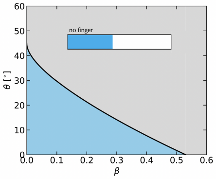
The equilibrium states are found by minimizing the interfacial energy for a fixed fluid volume in a static geometry. For the square tube with rounded corners, the phase diagram in the plane of contact angle and corner curvature reveals a bounded region where the partially wet state is favored over complete wetting or drying.
What carries the argument
The phase diagram in the parameter space of equilibrium contact angle and corner curvature, derived from energy minimization.
If this is right
- If the parameters are outside this region, the tube section will either fill completely or remain dry.
- Corner films form only when the contact angle allows partial wetting at the rounded corners.
- The theory applies to predicting fluid distribution in non-circular capillaries.
Where Pith is reading between the lines
- This could imply that in real tubes with slight rounding, corner flow might be suppressed for many contact angles.
- Experiments varying corner radius could test the boundaries of the partial wet region.
- Applications in oil recovery or inkjet printing might depend on tuning these parameters.
Load-bearing premise
The equilibrium states are determined solely by minimizing the interfacial energy for a fixed volume in a static tube geometry without gravity, flow, or dynamic effects.
What would settle it
Direct observation of whether corner films persist or disappear in a square capillary with controlled contact angle and corner radius would confirm or refute the phase boundaries.
Figures


read the original abstract
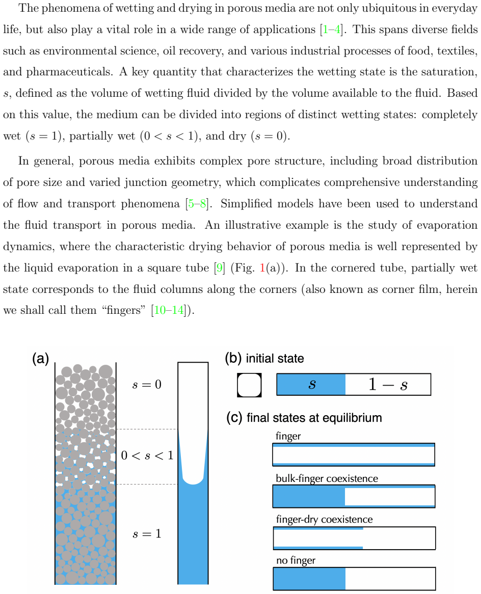
We develop a theory that predicts the equilibrium states of a fluid contained in a capillary which has corners. Each section of the tube can take three states: completely wet state where the tube section is completely occupied by the fluid, partially wet state where only the corners are occupied by the fluid known as corner film or finger, and completely dry state. We calculate the phase diagram of these states for a square tube with rounded corners. It is shown that the partially wet state can exist only in a certain region in the parameter space spanned by the equilibrium contact angle and the corner curvature.
Editorial analysis
A structured set of objections, weighed in public.
Referee Report
Summary. The paper develops a variational theory for the equilibrium states of a fixed-volume fluid in a capillary tube with corners, using a square cross-section with rounded corners as the model geometry. Three candidate states are considered: fully wet (tube section completely occupied by fluid), partially wet (fluid confined to corner films), and dry. The phase diagram in the plane of equilibrium contact angle and corner curvature is obtained by minimizing the interfacial energy of each configuration and determining the regions where each state has the lowest energy.
Significance. If the energy minimizations are correctly executed, the work supplies a concrete existence region for corner films, which is a useful addition to the literature on capillary wetting in non-circular channels. The approach follows the standard energy-comparison method for static capillary equilibria and could inform microfluidic design or porous-media modeling.
major comments (2)
- [§3] §3, Eq. (8): the interfacial energy for the partially wet state is written as a function of the meniscus curvature radius R and the corner radius r; the subsequent minimization with respect to R appears to be performed analytically, but the resulting expression for the critical contact angle boundary is not shown explicitly. Please insert the intermediate steps that lead from the energy functional to the phase-boundary curves plotted in Fig. 5.
- [§4.2] §4.2: the comparison between the three states assumes that the fluid volume is fixed and that gravity is absent. While this is appropriate for the static problem, the manuscript should state the range of Bond numbers for which the neglect of gravity remains valid, especially near the phase boundaries where the energy differences become small.
minor comments (2)
- [Abstract] The abstract states that the phase diagram is 'calculated,' yet the main text does not indicate whether the boundaries are obtained analytically or numerically; a brief sentence clarifying the method would improve clarity.
- [Figure 5] Figure 5 caption should explicitly label the three regions (wet, partially wet, dry) and indicate the direction of increasing corner curvature.
Simulated Author's Rebuttal
We thank the referee for the careful reading of our manuscript and the constructive comments. We address each major comment below and indicate the revisions that will be incorporated.
read point-by-point responses
-
Referee: [§3] §3, Eq. (8): the interfacial energy for the partially wet state is written as a function of the meniscus curvature radius R and the corner radius r; the subsequent minimization with respect to R appears to be performed analytically, but the resulting expression for the critical contact angle boundary is not shown explicitly. Please insert the intermediate steps that lead from the energy functional to the phase-boundary curves plotted in Fig. 5.
Authors: We agree that the derivation steps should be shown explicitly for transparency. In the revised manuscript we will insert the analytical minimization of the interfacial energy functional (Eq. 8) with respect to the meniscus radius R. This will yield the explicit relation for the critical contact angle as a function of the corner curvature parameter, directly connecting the energy expression to the phase-boundary curves in Fig. 5. No change to the final results is required. revision: yes
-
Referee: [§4.2] §4.2: the comparison between the three states assumes that the fluid volume is fixed and that gravity is absent. While this is appropriate for the static problem, the manuscript should state the range of Bond numbers for which the neglect of gravity remains valid, especially near the phase boundaries where the energy differences become small.
Authors: We accept that an explicit statement on the validity range is useful. In the revised §4.2 we will add a brief paragraph noting that the gravity-free assumption holds for Bond numbers Bo ≪ 1 (based on the tube radius and fluid properties), with a stricter criterion Bo < 0.1 recommended near the phase boundaries where interfacial energy differences are small. This addition clarifies the regime without altering the core analysis. revision: yes
Circularity Check
No significant circularity; energy comparison uses independent inputs
full rationale
The paper's central result is obtained by minimizing the interfacial energy for fixed volume in three distinct static configurations (fully wet, corner-film partially wet, and dry) and comparing those energies to delineate the phase diagram in the (contact angle, corner curvature) plane. Both the contact angle (from Young's law) and the geometric corner curvature are external parameters supplied to the model; neither is fitted to nor defined by the resulting existence boundaries. No load-bearing step reduces to a self-citation, an ansatz smuggled from prior work, or a renaming of an empirical pattern. The derivation is therefore self-contained and non-circular.
Axiom & Free-Parameter Ledger
axioms (2)
- domain assumption Equilibrium states are found by minimizing interfacial energy at fixed volume.
- standard math Contact angle is constant and given by Young's law on the solid surface.
Reference graph
Works this paper leans on
-
[1]
Jacob Bear,Dynamics of Fluids in Porous Media(Dover, 1972)
work page 1972
-
[2]
Pierre-Gilles de Gennes, Fran¸ coise Brochard-Wyart, and David Qu´ er´ e,Capillarity and Wet- ting Phenomena(Springer, 2004)
work page 2004
-
[3]
Wetting: statics and dynamics,
Pierre-Gilles de Gennes, “Wetting: statics and dynamics,” Rev. Mod. Phys.57, 827–863 (1985)
work page 1985
-
[4]
Daniel Bonn, Jens Eggers, Joseph Indekeu, Jacques Meunier, and Etienne Rolley, “Wetting and spreading,” Rev. Mod. Phys.81, 739–805 (2009)
work page 2009
-
[5]
Characteristic lengths affecting evaporative drying of porous media,
Peter Lehmann, Shmuel Assouline, and Dani Or, “Characteristic lengths affecting evaporative drying of porous media,” Phys. Rev. E77, 056309 (2008)
work page 2008
-
[6]
Analytical solutions of drying in porous media for gravity-stabilized fronts,
A. G. Yiotis, D. Salin, E. S. Tajer, and Y. C. Yortsos, “Analytical solutions of drying in porous media for gravity-stabilized fronts,” Phys. Rev. E85, 046308 (2012)
work page 2012
-
[7]
On the influence of pore shape, contact angle and film flows on drying of capillary porous media,
M. Prat, “On the influence of pore shape, contact angle and film flows on drying of capillary porous media,” Int. J. Heat Mass Transfer50, 1455–1468 (2007)
work page 2007
-
[8]
Scaling approach of the convective drying of a porous medium,
P. Coussot, “Scaling approach of the convective drying of a porous medium,” Eur. Phys. J. B 15, 557–566 (2000)
work page 2000
-
[9]
Three periods of drying of a single square capillary tube,
F. Chauvet, P. Duru, S. Geoffroy, and M. Prat, “Three periods of drying of a single square capillary tube,” Phys. Rev. Lett.103, 124502 (2009)
work page 2009
-
[10]
Capillary imbibition in a square tube,
Tian Yu, Jiajia Zhou, and Masao Doi, “Capillary imbibition in a square tube,” Soft Matter 14, 9263–9270 (2018)
work page 2018
-
[11]
Wetting equilibrium in a rectangular channel,
Tian Yu, Qicheng Sun, Chen Zhao, Jiajia Zhou, and Masao Doi, “Wetting equilibrium in a rectangular channel,” Soft Matter17, 3594–3602 (2021)
work page 2021
-
[12]
Wetting dynamics in an angular channel,
Chen Zhao, Tian Yu, Jiajia Zhou, and Masao Doi, “Wetting dynamics in an angular channel,” Langmuir37, 11276–11280 (2021)
work page 2021
-
[13]
Capillary rising in a tube with corners,
Chen Zhao, Jiajia Zhou, and Masao Doi, “Capillary rising in a tube with corners,” Langmuir 38, 5779–5786 (2022)
work page 2022
-
[14]
Capillary filling dynamics in polygonal tubes,
Chen Zhao, Yu Huang, Tingxuan Chen, Jiaxuan Li, Jiajia Zhou, and Masao Doi, “Capillary filling dynamics in polygonal tubes,” Phys. Fluids37, 042105 (2025)
work page 2025
-
[15]
Phase behavior and 12 morphology of multicomponent liquid mixtures,
Sheng Mao, Derek Kuldinow, Mikko P. Haataja, and Andrej Koˇ smrlj, “Phase behavior and 12 morphology of multicomponent liquid mixtures,” Soft Matter15, 1297–1311 (2019)
work page 2019
-
[16]
On the behavior of a capillary surface in a wedge,
Paul Concus and Robert Finn, “On the behavior of a capillary surface in a wedge,” PNAS 63, 292–299 (1969)
work page 1969
-
[17]
Dichotomous behavior of capillary surfaces in zero gravity,
P. Concus and R. Finn, “Dichotomous behavior of capillary surfaces in zero gravity,” Micro- gravity Sci. Technol.3, 87 (1990)
work page 1990
-
[18]
Cesare M. Cejas, Jean-Christophe Castaing, Larry Hough, Christian Fr´ etigny, and R´ emi Dreyfus, “Experimental investigation of water distribution in a two-phase zone during gravity- dominated evaporation,” Phys. Rev. E96, 062908 (2017)
work page 2017
-
[19]
Capillary-driven flow in corner geome- tries,
Nikolai Kubochkin and Tatiana Gambaryan-Roisman, “Capillary-driven flow in corner geome- tries,” Curr. Opin. Colloid Interface Sci.59, 101575 (2022)
work page 2022
-
[20]
The Gauss equation in capillarity,
Sun-Tak Hwang, “The Gauss equation in capillarity,” Zeitschrift f¨ ur Physikalische Chemie 105, 225–235 (1977)
work page 1977
-
[21]
Meniscus curvatures in capillaries of uniform cross- section,
Geoffrey Mason and Norman R. Morrow, “Meniscus curvatures in capillaries of uniform cross- section,” J. Chem. Soc., Faraday Trans. 180, 2375–2393 (1984)
work page 1984
-
[22]
Mercury porosimetry—breakthrough pressure for penetration between packed spheres,
Raymond P Mayer and Robert A Stowe, “Mercury porosimetry—breakthrough pressure for penetration between packed spheres,” J. Colloid Sci.20, 893–911 (1965)
work page 1965
-
[23]
Capillary phenomena in assemblies of parallel cylinders: I. capillary rise between two cylinders,
H. M. Princen, “Capillary phenomena in assemblies of parallel cylinders: I. capillary rise between two cylinders,” J. Colloid Interface Sci.30, 69 (1969)
work page 1969
-
[24]
H. M. Princen, “Capillary phenomena in assemblies of parallel cylinders: II. capillary rise in systems with more than two cylinders,” J. Colloid Interface Sci.30, 359 (1969)
work page 1969
-
[25]
H. M. Princen, “Capillary phenomena in assemblies of parallel cylinders: III. liquid columns between horizontal parallel cylinders,” J. Colloid Interface Sci.34, 171 (1970). 13 Appendix A: Different wetting cases Figure S1 show different wetting states for a circular tube, a square tube, and a square tube with rounded corners (from top to bottom). FIG. S1...
work page 1970
-
[26]
The radius of the interface is r1
Case I: full-circle meniscus Case I corresponds to a full circle of liquid-vapor interface. The radius of the interface is r1. The area of the liquid isS= 4a 2 −πr 2 1, thus the saturation is s= S S0 = 1− π 4 r1 a 2 ,(C1) ⇒ r1 a = r 4 π (1−s) 1/2 .(C2) The maximum ofr 1 is the half of the side-length,r 1 ≤a. This leads to lower bound for the saturations c...
-
[27]
On one corner, the meniscus touches the side wall at point B with a contact angleθ(Fig
Case II, corner meniscus Case II corresponds to the fingers at four corners. On one corner, the meniscus touches the side wall at point B with a contact angleθ(Fig. S2). This leads to ̸ BOC =θ. One eighth of the meniscus ⌢ BD is a portion of the circle with angleα= π 4 −θand radiusr 2. FIG. S2. Square tube, case II withθ < π 4 . The finger meniscus is con...
-
[28]
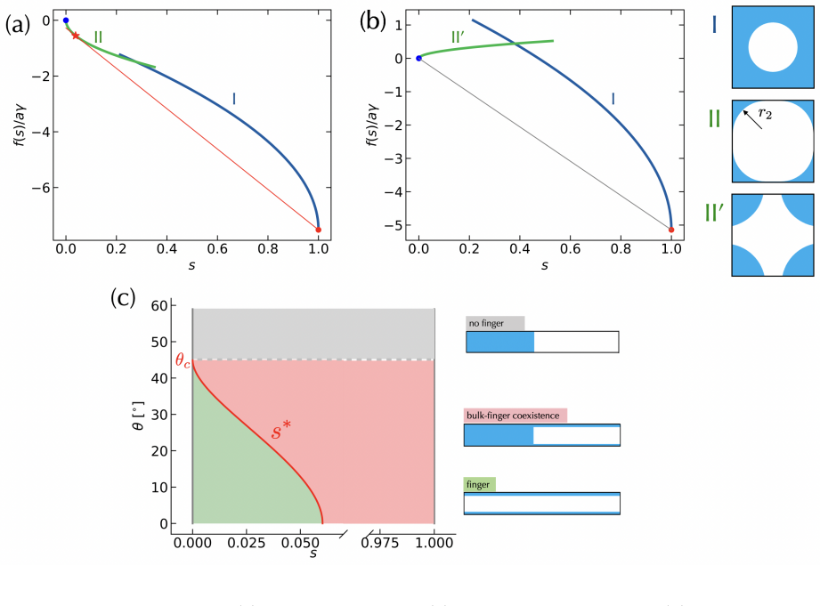
Summary of square tubef(s) We summarize the interfacial energy functions for square tube. •case I:s c1 ≤s≤1,s c1 = 1− π 4 f(s) aγ =−8 cosθ+ 4 √π(1−s) 1/2 (C25) •case II: 0≤s≤s c2,s c2 = A(θ) (cosθ−sinθ) 2 f(s) aγ =−sign π 4 −θ 8 p A(θ)s1/2 (C26) A(θ) is given in Eq. (C14). 18
-
[29]
Analysis of interfacial energyf(s) The interfacial energy curves forθ= 20 ◦ is shown in Fig. S4(a). The value off(s) varies significantly betweens= 0 ands= 1, making the line of tangency difficult to distinguish. For clear illustration, we define a new functiong(s) g(s) =f(s)−f(1)×s .(C27) This function satisfiesg(0) = 0 andg(1) = 0. It quantifies the dev...
-
[30]
The area of the liquid is givenS=S 0 −πr 2
Case I: full-circle meniscus Case I corresponds to a full circle of liquid-vapor interface of radiusr 1. The area of the liquid is givenS=S 0 −πr 2
-
[31]
The saturation is s= S S0 = 1− π 4B2(β) r1 a 2 ,(D4) ⇒ r1 a = r 4B2(β) π (1−s) 1/2 .(D5) The range of saturation in Case I is sc1 ≤s≤1, s c1 = 1− π 4B2(β) .(D6) The length of solid-liquid interface isL SL = 8a−8b+ 2πb= 8aB 1(β), and the length of liquid-vapor interface isL L V= 2πr1. The interfacial energy is then f(s) =L SL(−γcosθ) +L L Vγ=−8aγcosθB 1(β)...
-
[32]
On one corner, the meniscus touches the side wall at point B with a contact angleθ
Case II: corner meniscus, contact line on the straight side Case II of rounded corner is similar to the sharp corner. On one corner, the meniscus touches the side wall at point B with a contact angleθ. This leads to ̸ BOC =θ(Fig. S6). One eighth of the meniscus ⌢ BD is a portion of the circle with angleα= π 4 −θand radiusr 2. 21 FIG. S6. Square tube with ...
-
[33]
Case III: corner meniscus, contact line on the curved side For rounded corner, there is a case III when the saturation is small. The meniscus touches the solid surface on the rounded corner instead of the side-walls of the square (Fig. S8). The meniscus ⌢ BF is an arc with open angleα−θand radiusr 3. Comparing△CBG and △OBG BG =bsinα=r 3 sin(α−θ) (D26) ⇒r ...
-
[34]
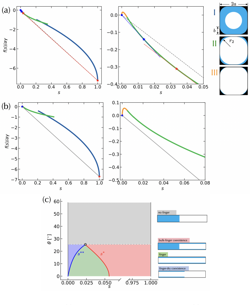
Summary of rounded cornerf(s) We summarize the interfacial energy functions for rounded corners. •case I:s c1 ≤s≤1,s c1 = 1− π 4B2(β) f(s) aγ =−8 cosθB 1(β) + 4 p πB2(β)(1−s) 1/2 (D38) •case II:s c3 ≤s≤s c2, sc2 = A(θ)(cosθ−sinθ) −2 −(1−B 2(β)) B2(β) sc3 = β2A(θ)(cosθ−sinθ) −2 −(1−B 2(β)) B2(β) f(s) aγ = 8(1−B 1(β)) cosθ−sign π 4 −θ 8 p A(θ) p B2(β)s+ (1−...
-
[35]
Oncexis obtained, we can use the reverse relation to gets ∗ s∗ = x2 −A(1−B 2) AB2 (E7) 27 FIG
calculation ofs ∗ The condition fors ∗ is f ′(s) = f(1)−f(s) 1−s ,(E3) which leads to −4AB2√ A p B2s+ (1−B 2) = −8 cosθ+ 8 √ A p B2s+ (1−B 2) 1−s (E4) Letx= √ A p B2s+ (1−B 2),xsatisfies the equation x2 −2 cosθx+A= 0 (E5) ⇒x= cosθ− √ cos2 θ−A .(E6) We chose the solution with negative sign. Oncexis obtained, we can use the reverse relation to gets ∗ s∗ = x...
-
[36]
calculation ofs ∗∗ The condition fors ∗∗ is f ′(s) = f(s) s ,(E8) which leads to −4AB2√ A p B2s+ (1−B 2) = 8(1−B 1) cosθ+ 8 √ A p B2s+ (1−B 2) s (E9) Lety= √ A p B2s+ (1−B 2),ysatisfies the equation y2 −2(1−B 1) cosθy+A(1−B 2) = 0 (E10) ⇒y= (1−B 1) cosθ− p (1−B 1)2 cos2 θ−A(1−B 2)2 .(E11) 28 FIG. S11. Square tube with rounded corners, interfacial energy c...
discussion (0)
Sign in with ORCID, Apple, or X to comment. Anyone can read and Pith papers without signing in.