A 100 GHz Wideband Reconfigurable Intelligent Surface Based on Orthogonal Polarization and Sub-Array Partitioning Concepts
Pith reviewed 2026-06-29 23:19 UTC · model grok-4.3
The pith
A PCB-based reconfigurable intelligent surface at 100 GHz achieves 10 dB gain enhancement from 86 to 100 GHz through orthogonal polarization and subarray partitioning.
A machine-rendered reading of the paper's core claim, the machinery that carries it, and where it could break.
Core claim
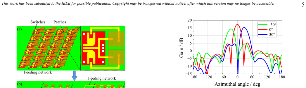
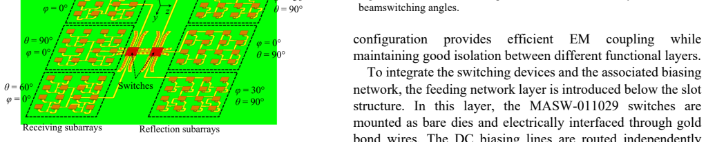
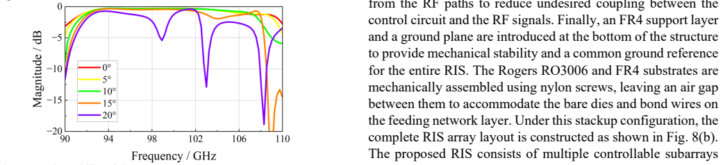
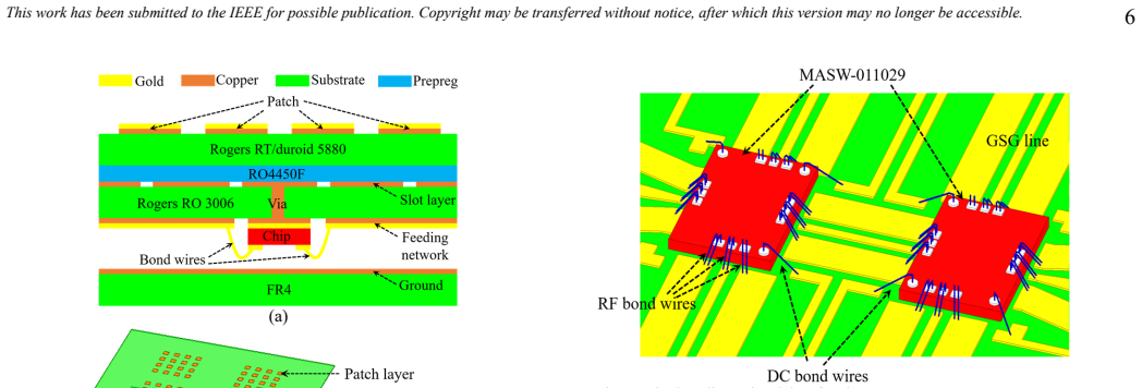
The paper presents a 100 GHz wideband RIS prototype fabricated on PCB that uses an orthogonal-polarization slot-coupled patch structure partitioned into subarrays. Reconfigurability for different beamforming angles is realized with AlGaAs SP3T bare-die switches connected through optimized bond-wire interconnections. Measurements on the 12 by 8 element design confirm gain enhancements of about 10 dB from 86 to 100 GHz and 5 dB from 100 to 106 GHz while consuming 0.165 W.
What carries the argument
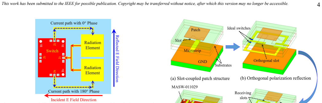
The orthogonal-polarization slot-coupled patch structure combined with subarray partitioning, which reduces switch count and parasitic effects to enable subarray-level beam control at 100 GHz.
If this is right
- The subarray approach enables multiple beamforming angles with reduced control complexity.
- Low power draw of 0.165 W supports deployment in energy-constrained sub-terahertz systems.
- PCB fabrication allows low-cost scaling for coverage enhancement in bands with high propagation loss.
Where Pith is reading between the lines
- The design may extend to larger arrays for testing coverage in realistic multi-user scenarios.
- Subarray partitioning could be adapted to other millimeter-wave frequencies where switch size limits unit-cell density.
- Integration with baseband processing might allow dynamic adaptation to changing blockage conditions.
Load-bearing premise
Bond-wire integration of the AlGaAs SP3T switches onto the orthogonal-polarization structure produces negligible parasitic effects and supports the intended subarray reconfigurability at 100 GHz.
What would settle it
Measurements on the prototype showing gain enhancement well below 10 dB from 86 to 100 GHz, or failure to achieve the designed beam angles, due to switch parasitic effects.
Figures


read the original abstract
The sub-terahertz frequency band offers extremely large bandwidth and enables ultra-high data rates for future wireless applications. However, severe propagation loss and blockage significantly limit coverage at these frequencies. Reconfigurable intelligent surfaces can dynamically shape EM wave propagation and provide a promising solution for coverage enhancement. Realizing such surfaces using standard printed circuit board technology is attractive due to its low cost and scalability, but it remains challenging around 100 GHz because of fabrication limits, limited switch availability, large switch size compared with the unit cell, switch parasitic effects, and high control complexity. In this work, we demonstrate a wideband PCB-based reconfigurable intelligent surface operating around 100 GHz. The design combines an orthogonal-polarization slot-coupled patch structure with subarray partitioning to mitigate switch-induced parasitic effects, reduce the required number of RF switches, and simplify the control architecture. The reconfigurability is achieved using AlGaAs SP3T bare-die switches integrated through optimized bond-wire interconnections. For proof of concept, a six-subarray structure with 4 by 4 elements per subarray is designed for different beamforming angles, and a 12 by 8 prototype is fabricated and experimentally characterized. The measured results show a gain enhancement of about 10 dB from 86 to 100 GHz and about 5 dB from 100 to 106 GHz, while maintaining a low power consumption of 0.165 W. These results validate the feasibility of practical wideband PCB-based reconfigurable intelligent surfaces for sub-terahertz wireless systems.
Editorial analysis
A structured set of objections, weighed in public.
Referee Report
Summary. The manuscript presents the design and experimental validation of a PCB-based reconfigurable intelligent surface (RIS) operating around 100 GHz. It combines an orthogonal-polarization slot-coupled patch unit cell with subarray partitioning to reduce the number of RF switches, simplify control, and mitigate parasitic effects from AlGaAs SP3T bare-die switches integrated via bond wires. A 12×8 prototype with six subarrays (4×4 elements each) is fabricated and measured, reporting approximately 10 dB gain enhancement from 86–100 GHz and 5 dB from 100–106 GHz at 0.165 W power consumption.
Significance. If the measured gain enhancements are confirmed to arise from the intended electromagnetic design rather than unaccounted integration effects, the work would demonstrate a practical route to wideband, low-power, PCB-fabricated RIS at sub-THz frequencies. This addresses key scalability barriers (switch size, parasitics, control complexity) and supplies concrete hardware data that could inform system-level studies of coverage enhancement in future wireless networks.
major comments (1)
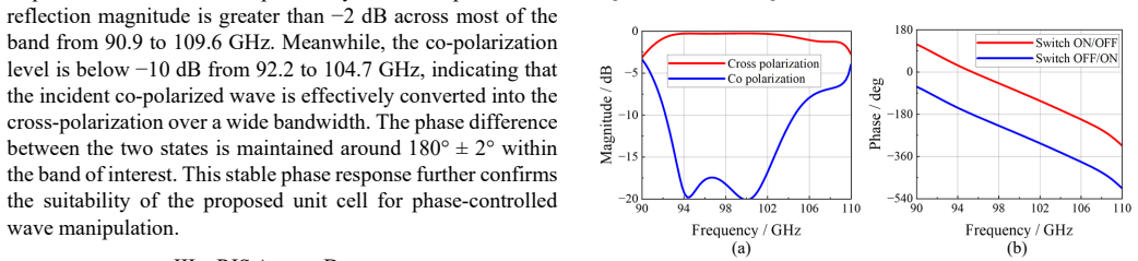
- [Abstract / Experimental Characterization] Abstract / Experimental Characterization: The central performance claims (10 dB gain enhancement 86–100 GHz, 5 dB 100–106 GHz) rest on the assertion that the slot-coupled orthogonal-polarization structure plus subarray partitioning renders AlGaAs SP3T switch and bond-wire parasitics negligible. No switch-level S-parameter data, de-embedding procedure, or measured-versus-simulated unit-cell comparison (with/without full switch model) is supplied; without these, the observed roll-off above 100 GHz cannot be unambiguously attributed to the intended EM design rather than integration parasitics.
Simulated Author's Rebuttal
We thank the referee for the constructive feedback. We address the single major comment below and will incorporate additional data to strengthen the experimental characterization.
read point-by-point responses
-
Referee: [Abstract / Experimental Characterization] The central performance claims (10 dB gain enhancement 86–100 GHz, 5 dB 100–106 GHz) rest on the assertion that the slot-coupled orthogonal-polarization structure plus subarray partitioning renders AlGaAs SP3T switch and bond-wire parasitics negligible. No switch-level S-parameter data, de-embedding procedure, or measured-versus-simulated unit-cell comparison (with/without full switch model) is supplied; without these, the observed roll-off above 100 GHz cannot be unambiguously attributed to the intended EM design rather than integration parasitics.
Authors: We agree that the manuscript would benefit from explicit supporting data on this point. In the revision we will add: (i) measured S-parameters of the bare-die AlGaAs SP3T switches over 80–110 GHz, (ii) a description of the de-embedding procedure used for the prototype, and (iii) simulated unit-cell reflection coefficients with and without the full switch-plus-bond-wire model. These additions will show that the orthogonal-polarization slot-coupled topology combined with 4×4 subarray partitioning keeps the parasitic impact small enough that the measured roll-off above 100 GHz is dominated by the intended EM design rather than integration effects. revision: yes
Circularity Check
No circularity: experimental hardware validation with no derivation chain
full rationale
The paper describes design, fabrication, and measurement of a PCB-based RIS prototype at ~100 GHz. Claims rest on measured gain enhancement (10 dB 86-100 GHz, 5 dB 100-106 GHz) and power consumption (0.165 W), not on any mathematical derivation, fitted parameters renamed as predictions, or self-citation load-bearing steps. No equations are presented that reduce outputs to inputs by construction. The reader's circularity score of 0.0 is confirmed; this is a standard experimental report whose validity is assessed by measurement reproducibility rather than internal logical reduction.
Axiom & Free-Parameter Ledger
Reference graph
Works this paper leans on
-
[1]
Considering both cost and availability, the MASW-011029 switch is selected in this work to realize the reconfigurable functionality of the RIS
and MASW-011029 [22] represent two typical commercially available solutions. Considering both cost and availability, the MASW-011029 switch is selected in this work to realize the reconfigurable functionality of the RIS. The MASW-011029 is a wideband single-pole triple-throw (SP3T) switch that provides a fast switching speed on the order of 2 ns, making i...
-
[2]
6G wireless systems: Vision, requirements, challenges, insights, and opportunities,
H. Tataria, M. Shafi, A. F. Molisch, M. Dohler, H. Sjoland, and ¨F. Tufvesson, “6G wireless systems: Vision, requirements, challenges, insights, and opportunities,” Proc. IEEE, vol. 109, no. 7,pp. 1166–1199, Jul. 2021
2021
-
[3]
What should 6G be?
S. Dang, O. Amin, B. Shihada, and M.-S. Alouini, “What should 6G be?” Nat. Electron., vol. 3, no. 1, pp. 20–29, Jan. 2020
2020
-
[4]
Reconfigurable hol ographic surfaces for ultra-massive MIMO in 6G: Practical design, optimization and implementation,
R. Deng et al., “Reconfigurable hol ographic surfaces for ultra-massive MIMO in 6G: Practical design, optimization and implementation,” IEEE J. Sel. Areas Commun., vol. 41, no. 8, pp. 2367–2379, Aug. 2023
2023
-
[5]
Device‐to‐Device Communication in 6G Using Machine Learning
Revathy, J. Shanthalakshmi, J. Mang aiyarkkarasi, and J. Matcha Rani. “Device‐to‐Device Communication in 6G Using Machine Learning.” Quantum Computing and Machine Learning for 6G, 261-282, 2026
2026
-
[6]
Smart Radio Environments Empowered byReconfigurable Intelligent Surf aces: How It Works, State of Research,and The Road Ahead,
M. Di Renzo et al., “Smart Radio Environments Empowered byReconfigurable Intelligent Surf aces: How It Works, State of Research,and The Road Ahead,” IEEE J. Sel. Areas Commun. , vol. 38, no. 11, pp.2450-2525, Nov. 2020
2020
-
[7]
Millimeter-wave RIS: Hardware design and system -level considerations,
R. Wang, P. Zheng, Y. Yang, X. Su, M. Vaseem, A. Chaaban, M. J.Hossain, T. Y. Al-Naffouri, and A. Shamim, “Millimeter-wave RIS: Hardware design and system -level considerations,” 2026. [Online]. Available: https://arxiv.org/abs/2602.23345
-
[8]
RIS in cellular networks-challenges and issues,
M. Åström, P. Gentner, O. Haliloglu, B. Makki, and O. Tageman, “RIS in cellular networks-challenges and issues,” 2024, arXiv:2404.04753
-
[9]
A. L. Imoize, V. B. Kumaravelu, and D.-T. Do, Reconfigurable Intelligent Surfaces for 6G and Beyond Wireless Networks. Hoboken, NJ,USA: Wiley, 2025
2025
-
[10]
220-GHz Liquid Crystal RIS-Aided Multi-User Terahertz Communication System: Prototyp e Design and Over-the-Air Experimental Trials
Y. Hou et al., “220-GHz Liquid Crystal RIS-Aided Multi-User Terahertz Communication System: Prototyp e Design and Over-the-Air Experimental Trials” IEEE Transactions on Wireless Communications , vol. 25, pp. 8534-8545, 2026
2026
-
[11]
Electronically reconfigur able reflectarray antenna based on single-layer liquid crystal with inde pendent dual-polari zation control,
R. Guirado, G. Perez-Palomino, P. de la Rosa, E. Carrasco, and X. Quintana, “Electronically reconfigur able reflectarray antenna based on single-layer liquid crystal with inde pendent dual-polari zation control,” IEEE Trans. Antennas Propag., vol. 72, no. 7, pp. 5626–5636, Jul. 2024
2024
-
[12]
A 265-GHz CMOS reflectarray with 98 × 98 elements for 1°-wide beam forming and high-angular-resolution radar imaging,
X. Chen et al., “A 265-GHz CMOS reflectarray with 98 × 98 elements for 1°-wide beam forming and high-angular-resolution radar imaging,” IEEE J. Solid-State Circuits, vol. 59, no. 11, pp. 3655–3669, Nov. 2024
2024
-
[13]
A high- speedprogrammable and scalable te rahertz holographic metasurface basedon tiled CMOS chips,
S. Venkatesh, X. Lu, H. Saei di, and K. Sengupta, “A high- speedprogrammable and scalable te rahertz holographic metasurface basedon tiled CMOS chips,” Nature Electron., vol. 3, no. 12, pp. 785– 793,Dec. 2020
2020
-
[14]
A wideband reconfigurable intelligent surface for 5G millimeter-wave applications,
R. Wang, Y. Yang, B. Makki, and A. Shamim, “A wideband reconfigurable intelligent surface for 5G millimeter-wave applications,” IEEE Trans. Antennas Propag., vol. 72, no. 3, pp. 2399–2410, Mar. 2024
2024
-
[15]
A 2-Bit Wideband 5G mm-Wave RIS With Low Sidelobe Levels and No Quantization Lobe,
R. Wang, Y. Yang and A. Shamim , “A 2-Bit Wideband 5G mm-Wave RIS With Low Sidelobe Levels and No Quantization Lobe,” IEEE Trans. Antennas Propag., vol. 73, no. 12, pp. 10042-10056, Dec. 2025
2025
-
[16]
A fully screen-printed vanadium-dioxide sw itch-based wideband reconfigurable intelligent surface for 5G and beyond,
Y. Yang, M. Vaseem, R. Wang, B. Makki, and A. Shamim, “A fully screen-printed vanadium-dioxide sw itch-based wideband reconfigurable intelligent surface for 5G and beyond,” IEEE Trans. Microw. Theory Techn., vol. 73, no. 9, pp. 5979–5991, Sep. 2025
2025
-
[17]
https://www.macom.com/products/product-detail/MA4AGFCP910
-
[18]
B roadband 1-bit Reconfigurable Intelligent Surface at Millimeter Waves: Overcoming P-I-N -Diode Degradation With Slotline Ring Topology,
Á. Palomares-Caballero, M. Pérez-Escr ibano, C. Molero, P. Padilla, M. García-Vigueras and R. Gillard, “B roadband 1-bit Reconfigurable Intelligent Surface at Millimeter Waves: Overcoming P-I-N -Diode Degradation With Slotline Ring Topology,” IEEE Trans. Antennas Propag., vol. 73, no. 8, pp. 5433-5445, Aug. 2025
2025
-
[19]
Cost-Effective Enhancement of RF Switch Perf ormance Utilizing Novel Coupling Structures,
J. Rao, Z. Ming, J. Zhang, C. -Y. Chiu and R. Murch, “Cost-Effective Enhancement of RF Switch Perf ormance Utilizing Novel Coupling Structures,” IEEE Trans. Microw. Theory Techn. , vol. 73, no. 12, pp.10135-10151, Dec. 2025
2025
-
[20]
https://www.eravant.com/75-to-110-ghz-30-db-isolation-wr-10 waveguide-w-band-reflective-sp4t-solid-state-switch
-
[21]
https://www.pasternack.com/pages/RF-Microwave-and-Millimeter Wave-Products/xx-bands-waveguide-to-coax-adapters.html
-
[22]
https://www.macom.com/products/product-detail/MASW-011111-DIE
-
[23]
https://www.macom.com/products/product-detail/MASW-011029
-
[24]
Complex permittivity measurement of dielectric substrate in sub-THz range,
H.-T. Zhu and K. Wu, “Complex permittivity measurement of dielectric substrate in sub-THz range,” IEEE Trans. THz Sci. Technol., vol. 11, no. 1, pp. 2–15, Jan. 2021
2021
-
[25]
Dualband circularly polarized shared-aperture Vivaldi MIMO antennawith linear- to-circular polarizer for 5G and 6G communication,
R. Wang, M. Ikram, Y. Yu, H. Zhang, and A. Shamim, “Dualband circularly polarized shared-aperture Vivaldi MIMO antennawith linear- to-circular polarizer for 5G and 6G communication,” IEEE Trans. Antennas Propag., vol. 73, no. 7, pp. 4300–4310,Jul. 2025
2025
-
[26]
https://www.macom.com/products/product-detail/MADR-009190- 000100
discussion (0)
Sign in with ORCID, Apple, or X to comment. Anyone can read and Pith papers without signing in.