Advancing Control Electronics for Next-Generation Astronomical Fiber Robotic Positioners
Pith reviewed 2026-06-26 19:34 UTC · model grok-4.3
The pith
A single board controls 42 motors for fiber positioners to 5 micrometer precision using sensorless methods.
A machine-rendered reading of the paper's core claim, the machinery that carries it, and where it could break.
Core claim
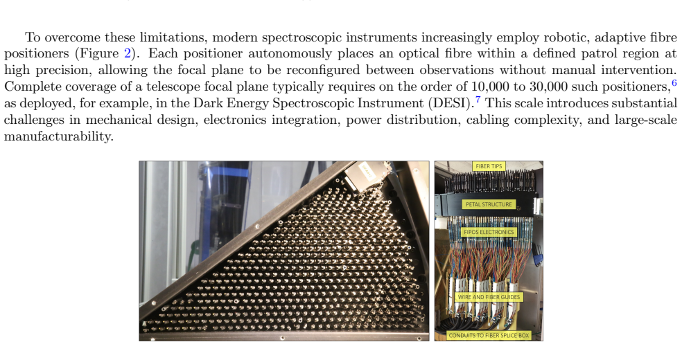
The module demonstrates that sensorless Field Oriented Control combined with collision detection and mechanical and magnetic hard-stop calibration can position 42 motors simultaneously to 5 micrometer accuracy on a single compact board, meeting the size and power constraints of next-generation spectroscopic survey instruments while eliminating the need for per-motor sensors or dedicated control hardware.
What carries the argument
Sensorless Field Oriented Control with collision detection and hard-stop calibration that achieves positioning without Hall sensors or encoders.
If this is right
- Future survey instruments can pack more positioners into the same focal-plane volume.
- System cost and complexity drop by removing encoders and dedicated boards per positioner.
- Energy efficiency improves because one board handles power distribution and synchronization for the entire group.
- Simultaneous motion becomes feasible through the added synchronization line without cross-talk.
Where Pith is reading between the lines
- The same sensorless approach might apply to other precision mechanisms where adding sensors increases mass or failure points.
- Scaling the board to larger motor counts would require testing thermal and electromagnetic interference limits not detailed here.
- Similar calibration routines could reduce maintenance time in remote observatory settings.
Load-bearing premise
Sensorless field-oriented control with collision detection and hard-stop calibration can deliver reliable 5 micrometer accuracy for 42 motors running at once in a dense setup without any position sensors.
What would settle it
A measurement showing positioning error larger than 5 micrometers for the full set of 42 motors operating simultaneously under typical survey load and vibration conditions.
Figures


read the original abstract
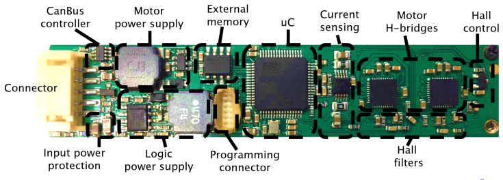
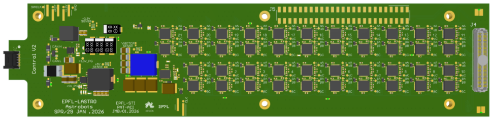
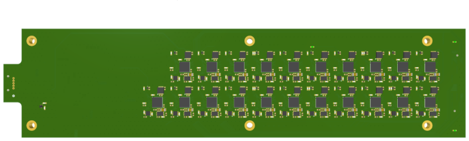
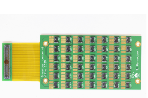
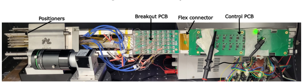
Next-generation spectroscopic surveys require compact, high-density fiber robotic positioner systems achieving 5um precision, placing strict constraints on the size and the power budget of the control electronics. We present a compact control electronics architecture that drives 21 theta phi SCARA positioners (42 BLDC motors) on a single board, representing a significant increase in complexity compared to the electronics used in ongoing surveys such as SDSS V and DESI, where each positioner relies on dedicated hardware. The design integrates power distribution, CAN communication, and a synchronization line for simultaneous motion in high-density environments. Sensorless Field Oriented Control with collision detection and mechanical and magnetic hard-stop calibration enables accurate positioning without Hall sensors or encoders, reducing system cost and complexity. We describe the system architecture and performance validation, demonstrating that the module meets precision requirements while reducing the space required for control electronics and improving energy efficiency for future survey instruments.
Editorial analysis
A structured set of objections, weighed in public.
Referee Report
Summary. The manuscript presents a compact control electronics architecture that drives 42 BLDC motors (21 theta-phi SCARA positioners) on a single board for next-generation fiber positioner systems. It integrates power distribution, CAN communication, and a synchronization line, and employs sensorless Field Oriented Control combined with collision detection and mechanical/magnetic hard-stop calibration to achieve 5 μm positioning accuracy without Hall sensors or encoders, claiming reduced space and improved energy efficiency relative to dedicated hardware in surveys such as SDSS-V and DESI.
Significance. If the performance claims hold, the architecture offers a practical route to higher-density positioner arrays for future spectroscopic surveys by consolidating electronics and lowering power and complexity. The approach directly addresses scaling constraints for instruments requiring thousands of positioners.
major comments (1)
- [Abstract and performance validation section] Performance validation description (Abstract and associated section): The central claim that the module meets 5 μm precision requirements rests on an asserted 'performance validation,' yet the text supplies no quantitative data such as RMS positioning errors, error budgets, test conditions for simultaneous operation of all 42 motors, thermal/EMI effects, or startup transients. Without these measurements, the reliability of sensorless FOC plus hard-stop calibration under full load cannot be assessed.
Simulated Author's Rebuttal
We thank the referee for their constructive review. The single major comment is addressed below; we will revise the manuscript to strengthen the performance validation section.
read point-by-point responses
-
Referee: [Abstract and performance validation section] Performance validation description (Abstract and associated section): The central claim that the module meets 5 μm precision requirements rests on an asserted 'performance validation,' yet the text supplies no quantitative data such as RMS positioning errors, error budgets, test conditions for simultaneous operation of all 42 motors, thermal/EMI effects, or startup transients. Without these measurements, the reliability of sensorless FOC plus hard-stop calibration under full load cannot be assessed.
Authors: We agree that the current description of performance validation lacks sufficient quantitative detail. In the revised manuscript we will expand the relevant section (and update the abstract if needed) to report RMS positioning errors, a full error budget, explicit test conditions including simultaneous drive of all 42 motors, and quantitative discussion of thermal/EMI effects and startup transients. These additions will directly substantiate the 5 μm claim under representative load. revision: yes
Circularity Check
No circularity: hardware architecture report with no derivation chain
full rationale
The manuscript describes a compact control electronics board for 42 BLDC motors, integrating power distribution, CAN bus, synchronization, and sensorless FOC with collision detection and hard-stop calibration. No equations, fitted parameters, predictions, or mathematical derivations appear anywhere in the text. Claims of meeting 5 μm precision rest on asserted performance validation rather than any reduction of outputs to inputs by construction, self-citation chains, or ansatz smuggling. This is a standard engineering hardware report whose central assertions are independent of the circularity patterns enumerated; the absence of any load-bearing derivation makes the score 0.
Axiom & Free-Parameter Ledger
Reference graph
Works this paper leans on
-
[1]
G. J. Alred and C. T. Brusaw and W. E. Oliu. Handbook of Technical Writing. 2015 (eleventh edition)
2015
-
[2]
The LaTeX Companion
Michel Goossens and Frank Mittelbach and Sebastian Rahtz. The LaTeX Companion. 1997
1997
-
[3]
The LaTeX Companion
Frank Mittelbach and Michel Goossens and Johannes Braams and David Carlisle. The LaTeX Companion. 2004
2004
-
[4]
S. F. Gull. Developments in maximum-entropy data analysis. Maximum Entropy and Bayesian Methods. 1989
1989
-
[5]
K. M. Hanson. Introduction to B ayesian image analysis. Medical Imaging:\ Image Processing. 1993
1993
-
[6]
L. Lamport. LaTeX: A Document Preparation System. 1994
1994
-
[7]
Metropolis and A
N. Metropolis and A. W. Rosenbluth and M. N. Rosenbluth and A. H. Teller and E. Teller. Equations of state calculations by fast computing machine. J. Chem. Phys. 1953
1953
-
[8]
L. C. Perelman and J. Paradis and E. Barrett. Mayfield Handbook of Technical and Scientific Writing. 1997
1997
-
[9]
John D Lees-Miller , title =
-
[10]
2024 , eprint=
WST -- Widefield Spectroscopic Telescope: Motivation, science drivers and top-level requirements for a new dedicated facility , author=. 2024 , eprint=
2024
-
[11]
2025 , eprint=
MUltiplexed Survey Telescope: Perspectives for Large-Scale Structure Cosmology in the Era of Stage-V Spectroscopic Survey , author=. 2025 , eprint=
2025
-
[13]
Flaugher, Brenna and Bebek, Chris and. The. 2014 , institution =
2014
-
[14]
2025 , eprint=
Prototyping of 6.2-mm-Pitch Fiber Positioner Modules for Stage-V Telescope Instrumentation , author=. 2025 , eprint=
2025
-
[15]
Journal of Astronomical Telescopes, Instruments, and Systems , number =
Luzius Kronig and Philipp H. Journal of Astronomical Telescopes, Instruments, and Systems , number =. 2020 , doi =
2020
-
[16]
Silber and al. , year=. The Robotic Multiobject Focal Plane System of the Dark Energy Spectroscopic Instrument (DESI) , volume=. The Astronomical Journal , publisher=. doi:10.3847/1538-3881/ac9ab1 , number=
-
[17]
Owen, R. E. , title =. Proceedings of SPIE, Astronomical Instrumentation , volume =. 1994 , doi =
1994
-
[18]
2020 , language =
Luzius Gregor Kronig , title =. 2020 , language =
2020
-
[19]
Hill, J. M. and Angel, J. R. P. and Scott, J. S. and Lindley, D. and Hintzen, P. , title =. The Astrophysical Journal Letters , volume =
-
[20]
Smee, Stephen A. and al. , year=. THE MULTI-OBJECT, FIBER-FED SPECTROGRAPHS FOR THE SLOAN DIGITAL SKY SURVEY AND THE BARYON OSCILLATION SPECTROSCOPIC SURVEY , volume=. The Astronomical Journal , publisher=. doi:10.1088/0004-6256/146/2/32 , number=
-
[21]
Monthly Notices of the Royal Astronomical Society , volume =
Hörler, Philipp and Kronig, Luzius and Kneib, Jean-Paul and Bouri, Mohamed and Bleuler, Hannes and von Moos, Dieter , title =. Monthly Notices of the Royal Astronomical Society , volume =. 2018 , doi =
2018
-
[22]
Blanton and al. , year=. Sloan Digital Sky Survey IV: Mapping the Milky Way, Nearby Galaxies, and the Distant Universe , volume=. The Astronomical Journal , publisher=. doi:10.3847/1538-3881/aa7567 , number=
-
[23]
2026 , note =
Tarik, Ibrahimovic , title =. 2026 , note =
2026
-
[24]
Advancing Control Electronics for Next-Generation Astronomical Fiber Robotic Positioners , booktitle =
Pernecker, S\'. Advancing Control Electronics for Next-Generation Astronomical Fiber Robotic Positioners , booktitle =. 2026 , note =
2026
discussion (0)
Sign in with ORCID, Apple, or X to comment. Anyone can read and Pith papers without signing in.