REVIEW 3 major objections 5 minor 52 references
Beyond the Plane: Coupling Planar Vehicle Dynamics with Three-Dimensional Road Geometry
T0 review · 3 major / 5 minor · reviewed 2026-08-11 · deepseek-v4-flash
Pith's one-line read A wrapping module lets a planar vehicle dynamics model reproduce measured three-dimensional accelerations and yaw rates on banked roads, cutting mean absolute error by roughly 95% for vertical and 78% for lateral acceleration.
desk verdict A useful black-box module for adding 3D road effects to planar vehicle models, but the headline real-data numbers validate the kinematic transformation, not the force-feedback dynamics. read the letter →
The pith
A machine-rendered reading of the paper's core claim, the machinery that carries it, and where it could break.
The reading
What carries the argument
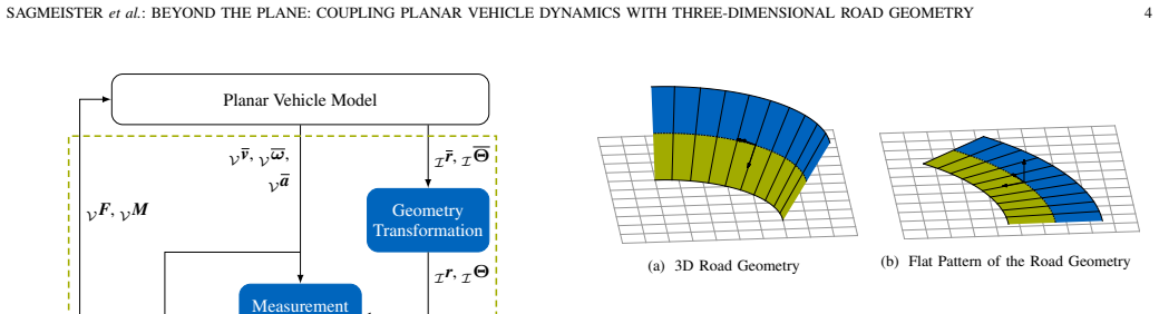
The load-bearing object is the ribbon track representation: a 3D road described by a spine curve plus a lateral offset, with curvature $\Omega_z$, banking $\varphi$, and slope $\mu$ that depend only on arc length $s$. Onto this ribbon the method projects a 'road plane'—the surface cut into infinitesimal slices and laid flat—constructed by numerically integrating the curvature with a circular-arc scheme that avoids accumulation error at low curvature. Curvilinear coordinates $(s, n, \chi)$ are preserved between the plane and the 3D ribbon, which makes the pose transformation well-defined, with the full orientation built from $R_{IV} = R_z(\theta)R_y(\mu)R_x(\varphi)R_z(\chi-\beta)$. The measurement transformations (velocity, angular velocity, acceleration, angular acceleration) and the vehicle-load calculation ($F = ma$ plus angular momentum with a diagonal inertia tensor) then convert planar outputs into 3D sensor-equivalent signals and feed the geometry-induced increments back as external forces and moments at the center of gravity. This force and moment feedback is what changes the planar model's behavior, and the geometry transformation is what explains the yaw-rate correction, since yaw rate itself is not transformed.
What would settle it
Drive the same simulation on a road with laterally varying banking, such as a crowned or rutted road, and compare predicted vertical acceleration with measured values: because the ribbon cannot represent lateral banking variation, agreement should degrade exactly where the paper's synthetic and real tests do not probe. Alternatively, perturb the extracted spine geometry by a 0.5 m lateral offset or a 1-degree banking change and check whether the predicted corrections shift by a comparable amount; if they do, the reported error reductions depend on the accuracy of the geometry extraction from low-speed laps.
Extended reading notes
Core claim
The paper's central claim is that a planar vehicle dynamics model, treated as a black box, can be wrapped in a module that adapts it to 3D roads. The module does three things: it transforms the planar pose into a 3D pose on the road (geometry transformation), transforms the planar velocities, accelerations, and angular rates into their 3D equivalents including gravitational components (measurement transformation), and computes the extra forces and moments the road geometry induces, applied at the center of gravity. Because force and moment feedback changes what the planar model feels, the loop is closed. On the banked Las Vegas Motor Speedway, the approach reproduces measured accelerations and angular rates of a full-scale race car, where the planar baseline cannot; the largest error reductions are in vertical and lateral acceleration and yaw rate, and a closed-loop evaluation with a planar dual-track model and a motion controller remains stable. The authors do not claim to beat full 3D multi-body models, only to close most of the gap while keeping the planar model's speed and interpretability.
Load-bearing premise
The method stands on the road being representable as a ribbon—curvature, banking, and slope varying only with arc length—and on the vehicle staying close enough to the spine that the projection onto the flattened road plane is unambiguous; if the road banks differently across its width or the car drifts far laterally, the corrections inherit that error, and the paper provides no sensitivity analysis.
Editorial extensions
If this is right
- Planar vehicle models can be used on real 3D roads without reformulating their equations, preserving their interpretability for control and state-estimation development.
- The method runs at a mean 9.5 microseconds per step, making it usable for real-time simulation and sped-up training of reinforcement-learning agents.
- Banked-road normal loads, which exceed the nominal load by over 66% on the Las Vegas track, are recovered well enough to alter tire-load-dependent dynamics in simulation.
- Because the geometry transformation alone fixes most of the yaw-rate error, planar controllers evaluated on bird's-eye-view maps will see the road-plane behavior they would encounter in reality.
- The open-source implementation lets other planar models be coupled as long as they accept external forces and moments as inputs.
Reading between the lines
- The reported error reductions come from one track and one racing line, and the ribbon input is extracted from the same vehicle's low-speed laps, so geometry-extraction error is a plausible hidden source of bias in the validation numbers.
- The same wrapping strategy should transfer to smooth, ribbon-representable roads such as highways and test tracks; roads with curbs, bumps, or laterally varying banking would need a superimposed local surface model, which the paper itself proposes as future work.
- Because yaw rate is corrected by the geometry transformation rather than by force feedback, control algorithms tuned on flat-road simulations could be re-tuned on the road-plane reference line to match banked-oval behavior before track testing.
- A natural extension is pairing the coupling with a tire model that explicitly uses the recovered normal load, since the 66% load increase would change friction limits and vehicle response in ways a point-mass validation cannot show.
Signed reviews
Editorial analysis
A structured set of objections, weighed in public.
Referee Report
Summary. The paper proposes a black-box coupling module that lets an existing planar vehicle dynamics model run on three-dimensional road geometry. The method consists of (i) a geometry transformation that projects the planar pose onto a ribbon-represented 3D road, (ii) transformations of velocity, angular velocity, acceleration, and angular acceleration into their 3D counterparts, and (iii) computation of geometry-induced forces and moments applied as external loads to the planar model. The authors validate on four synthetic tracks and on real high-speed data from a race car at Las Vegas Motor Speedway, reporting large reductions in mean absolute error versus a planar baseline, and they provide an open-source C++ implementation.
Significance. The core algebraic derivations in Sections III-D through III-F, including the cross-product expansion in Eq. (26) and the gravity projection in Eq. (27), are internally consistent, and the open-source implementation makes the method immediately usable and reproducible. If the real-data validation were quantitative for the closed-loop dynamic case, this would be a practically valuable contribution: it would let developers keep the interpretability and low cost of planar models while capturing banked-road and elevation effects that are otherwise missed. The synthetic-track experiments (Figs. 10-12) convincingly demonstrate that the transformation produces physically sensible signals in extreme geometry. However, the current real-data evidence is largely kinematic rather than dynamic, so the central claim about closing the gap between planar simulation and real 3D roads is only conditionally supported.
major comments (3)
- [Section IV-B, Table II] The quantitative validation is performed with a planar point-mass model that 'perfectly tracks the road plane reference line in an open-loop simulation' (Section IV, first paragraph). Because the trajectory is prescribed, the forces and moments from Section III-F (Eqs. (34) and (38)) do not feed back into the simulated state; the reported error reductions of about 95% for az, 78% for ay, and 82% for the yaw-rate bias in Table II therefore measure how well the kinematic measurement transformation plus extracted track geometry reconstruct the recorded IMU signals at constant 69.5 m/s, not how well the dynamic coupling preserves vehicle dynamics. The closed-loop dual-track evaluation in Figs. 15 and 16 is qualitative and explicitly not intended to replicate the real oscillations, and it is not scored in Table II. The abstract's statement that the gap between planar simulation and real-world 3D roads is closed thus needs either a quantitative closed-loop comparison or a more modestly scoped claim.
- [Table II, Section IV-B] Table II reports errors only over 10% to 45% of the lap, which the authors state is the portion where the 3D geometry effects are most pronounced. Restricting the comparison to this segment can inflate the apparent improvement and leaves the full-lap behavior unknown. Please provide full-lap metrics, or justify the segment choice by showing that the planar baseline is already accurate over the rest of the lap and that the conclusion is insensitive to the segment boundaries.
- [Sections III-B, III-D, and V] The validation inherits the ribbon track representation, with curvature, banking, and slope extracted from low-speed laps using an approach adapted from Perantoni and Limebeer [27]. The paper provides no sensitivity analysis of the predicted corrections to errors in this geometry extraction, nor to lateral deviations from the reference line, even though Section III-D itself notes that the road-plane projection must remain injective and Section V concedes that laterally varying and uneven roads break the ribbon assumption entirely. Since the corrections in Eqs. (29) and (34) are directly proportional to the geometric quantities, a small extraction error propagates linearly into the reported accelerations; at minimum, the authors should report the expected error level of the geometry extraction or run a perturbation study on the Las Vegas data.
minor comments (5)
- [Introduction] There is a typo in the fourth paragraph: 'Intertial Measurement Unit' should be 'Inertial Measurement Unit'.
- [Fig. 3] The description refers to 'modules drawn in blue', but the figure may not be distinguishable in grayscale; please use labels or a colorblind-safe palette in addition to color.
- [Table I] The vehicle parameters are said to be 'approximated from the recorded data'; please state how each parameter was estimated and, if possible, give an uncertainty range, since some predicted moments depend linearly on Ix, Iy, and Iz.
- [Section IV-B] The 2.0 Hz lowpass filter cutoff for the real-world IMU data is stated but not justified; a sentence explaining that the cutoff was chosen to remove sensor noise and vibration while preserving the track-induced dynamics would help reproducibility.
- [Section III-D] The small-angle approximation in Eqs. (9)-(10) is correct but would be clearer if it were stated as the leading-order Taylor expansion of (1-cos(alpha))/Omega_z,m and sin(alpha)/Omega_z,m, since the current text leaves the limit step implicit.
Circularity Check
No significant circularity; only minor non-load-bearing self-citations for the open-source dual-track model.
full rationale
The derivation chain in Sections III-D through III-F is self-contained: the geometry transformation preserves curvature and arc length and constructs the planar reference line from the measured curvature profile; the measurement transformation (Eqs. 20-30) is a forward kinematic mapping from track geometry and planar state to three-dimensional IMU quantities; and the force/moment feedback (Eqs. 32-38) is the difference between the spatial and planar rigid-body loads. The real-data validation uses track characteristics computed from independent low-speed laps (Fig. 14) to predict high-speed 69.5 m/s IMU data that were not used to fit the geometry, so the agreement in Table II is a cross-check of the forward model rather than a fit renamed as a prediction. The open-loop point-mass setup (Section IV-B) means the reported ME/MAE reductions do not exercise the dynamic feedback, and the closed-loop dual-track comparison is qualitative; this limits what the validation demonstrates, but it does not make any predicted quantity equal to its input by construction. The self-citations to the authors' openly available dual-track model ([4], [45]) are tool citations that are reproducible and not load-bearing to the central claim. Section V's stated limitations (rigid-body center-of-gravity collapsing, ribbon-only road shapes) are acknowledged scope restrictions, not hidden circular dependencies.
Assumptions & free parameters
free parameters (5)
- vehicle mass m =
800 kg
- center-of-gravity height h =
0.3 m
- moments of inertia Ix, Iy, Iz =
100 / 500 / 1000 kg m^2
- measurement filter cutoff =
2.0 Hz
- planar reference line segment window =
100 points at 1 m spacing
assumptions (7)
- domain assumption The 3D road is representable as a ribbon: a spine curve plus lateral offset, with curvature, banking, and slope that depend only on arc length.
- domain assumption All road-induced loads can be collected at the center of gravity; suspension kinematics and gyroscopic moments are negligible.
- domain assumption The road-plane projection preserves curvature and arc length by construction and remains injective over the simulated trajectory.
- standard math Standard Newton-Euler rigid-body kinematics with gravity projection are valid for the corrected 3D state.
- domain assumption Tire normal load is adequately represented by rigid-body vertical specific force, without a tire or suspension model in the quantitative validation.
- domain assumption The racing-line geometry extracted from low-speed laps of the same vehicle is accurate enough for predictions at 69.5 m/s.
- ad hoc to paper Aerodynamic loads on the race car at about 250 km/h are negligible for the validation signals.
Cite this review
Pith. "Pith review of Beyond the Plane: Coupling Planar Vehicle Dynamics with Three-Dimensional Road Geometry." pith.science (2026). https://pith.science/paper/QMAFTVS3
@misc{pith2026260809402,
  author       = {Pith},
  title        = {Pith review of: Beyond the Plane: Coupling Planar Vehicle Dynamics with Three-Dimensional Road Geometry},
  year         = {2026},
  howpublished = {\url{https://pith.science/paper/QMAFTVS3}},
  note         = {Machine review of arXiv:2608.09402}
}
read the original abstract
Simulation is crucial for developing and testing autonomous driving systems. In particular, the development of localization and control algorithms relies on an accurate vehicle dynamics simulation. However, most vehicle dynamics models are two-dimensional while real-world roads are three-dimensional. For example, effects from the three-dimensional road geometry on the Las Vegas Motor Speedway can increase the normal forces on the tires by more than 66% compared to the nominal load at standstill. As a result, even highly detailed planar vehicle dynamics models struggle to accurately reproduce the real vehicle's behavior. While solutions for three-dimensional vehicle dynamics exist, they are rarely adopted, computationally expensive, and complex. To address this issue, we present a novel method to couple planar vehicle dynamics models with real-world three-dimensional road geometry. We transform the planar vehicle state from the vehicle model's two-dimensional plane to its corresponding representation in three-dimensional space. Additionally, we calculate road-geometry-induced forces and moments and apply them to the planar vehicle model. We validate our approach using high-speed data recorded with a full-scale race car on the banked Las Vegas Motor Speedway. Furthermore, on synthetic tracks, we show that our method yields accurate results even in edge cases. Together, our results demonstrate that the gap between planar simulation and real-world three-dimensional roads can be closed without abandoning simpler planar models. To simplify adoption of our method, we provide the implementation as open-source software on github.com/TUMFTM/3d-road-geometry-coupling.
Figures


Figures from the paper (10 more)


Reference graph
Works this paper leans on
-
[27]
G. Perantoni and D. J. N. Limebeer, “Optimal Control of a Formula One Car on a Three-Dimensional Track—Part 1: Track Modeling and Identification,”Journal of Dynamic Systems, Measurement, and Control, vol. 137, no. 5, p. 051018, May 2015. [Online]. Available: https: //asmedigitalcollection.asme.org/dynamicsystems/article/doi/10.1115/ 1.4028253/370529/Optim...
work page 2015
-
[1]
A comparative study on trajectory tracking control methods for automated vehicles,
D. Zenget al., “A comparative study on trajectory tracking control methods for automated vehicles,”Scientific Reports, vol. 15, no. 1, p. 17073, May 2025. [Online]. Available: https://www.nature.com/articles/ s41598-025-01365-9
work page 2025
-
[2]
Comparison of trajectory tracking controllers for autonomous vehicles,
D. Calzolari, B. Schurmann, and M. Althoff, “Comparison of trajectory tracking controllers for autonomous vehicles,” in2017 IEEE 20th International Conference on Intelligent Transportation Systems (ITSC). Yokohama: IEEE, Oct. 2017, pp. 1–8. [Online]. Available: http://ieeexplore.ieee.org/document/8317800/
-
[3]
Tube model predictive control for an autonomous race car,
A. Wischnewski, M. Euler, S. G ¨um¨us, and B. Lohmann, “Tube model predictive control for an autonomous race car,”Vehicle System Dynamics, vol. 60, no. 9, pp. 3151–3173, Sep. 2022. [Online]. Available: https://www.tandfonline.com/doi/full/10.1080/00423114.2021.1943461
arXiv 2022
-
[4]
Analyzing the Impact of Simulation Fidelity on the Evaluation of Autonomous Driving Motion Control,
S. Sagmeister, P. Kounatidis, S. Goblirsch, and M. Lienkamp, “Analyzing the Impact of Simulation Fidelity on the Evaluation of Autonomous Driving Motion Control,” in2024 IEEE Intelligent Vehicles Symposium (IV). Jeju Island, Korea, Republic of: IEEE, Jun. 2024, pp. 230–237. [Online]. Available: https://ieeexplore.ieee.org/ document/10588858/
-
[5]
Optimization-Based Autonomous Racing of 1:43 Scale RC Cars
A. Liniger, A. Domahidi, and M. Morari, “Optimization-Based Autonomous Racing of 1:43 Scale RC Cars,”Optimal Control Applications and Methods, vol. 36, no. 5, pp. 628–647, Sep. 2015. [Online]. Available: http://arxiv.org/abs/1711.07300
work page Pith review arXiv 2015
-
[6]
Stanley: The Robot that Won the DARPA Grand Challenge,
S. Thrunet al., “Stanley: The Robot that Won the DARPA Grand Challenge,”Journal of Field Robotics, vol. 23, no. 9, pp. 661–692, Sep. 2006
work page 2006
-
[7]
P. Mitchell, “Indy Autonomous Challenge,” 2024. [Online]. Available: https://www.indyautonomouschallenge.com/
work page 2024
Show all 52 references
-
[8]
Online Time-Optimal Trajectory Planning on Three-Dimensional Race Tracks,
M. Rowold, L. ¨Ogretmen, U. Kasolowsky, and B. Lohmann, “Online Time-Optimal Trajectory Planning on Three-Dimensional Race Tracks,” in2023 IEEE Intelligent Vehicles Symposium (IV). Anchorage, AK, USA: IEEE, Jun. 2023, pp. 1–8. [Online]. Available: https://ieeexplore.ieee.org/d...
2023
-
[9]
Optimal Control of a Formula One Car on a Three-Dimensional Track—Part 2: Optimal Control,
D. J. N. Limebeer and G. Perantoni, “Optimal Control of a Formula One Car on a Three-Dimensional Track—Part 2: Optimal Control,”Journal of Dynamic Systems, Measurement, and Control, vol. 137, no. 5, p. 051019, May 2015. [Online]. Available: https: //asmedigitalcollection.asme....
2015
-
[10]
Curved-ribbon-based track modelling for minimum lap-time optimisation,
S. Lovato, M. Massaro, and D. J. N. Limebeer, “Curved-ribbon-based track modelling for minimum lap-time optimisation,”Meccanica, vol. 56, no. 8, pp. 2139–2152, Aug. 2021. [Online]. Available: https://link.springer.com/10.1007/s11012-021-01387-3
2021 doi
-
[11]
Sampling- Based Motion Planning with Online Racing Line Generation for Autonomous Driving on Three-Dimensional Race Tracks,
L. ¨Ogretmen, M. Rowold, A. Langmann, and B. Lohmann, “Sampling- Based Motion Planning with Online Racing Line Generation for Autonomous Driving on Three-Dimensional Race Tracks,” in2024 IEEE Intelligent Vehicles Symposium (IV). Jeju Island, Korea, Republic of: IEEE, Jun. 2024...
2024
-
[12]
Modelling and control for high-sideslip vehicles on nonplanar roads,
L. Ruifeng, R. Hongbin, and C. Chih-Keng, “Modelling and control for high-sideslip vehicles on nonplanar roads,”Vehicle System Dynamics, pp. 1–26, Apr. 2026. [Online]. Available: https: //www.tandfonline.com/doi/full/10.1080/00423114.2026.2660695
2026
-
[13]
Non-euclidean vehicle motion models,
T. D. Fork, “Non-euclidean vehicle motion models,” Ph.D. dissertation, University of California, Berkeley, 2024
2024
-
[14]
Models and Predictive Control for Nonplanar Vehicle Navigation,
T. Fork, H. E. Tseng, and F. Borrelli, “Models and Predictive Control for Nonplanar Vehicle Navigation,” in2021 IEEE International Intelligent Transportation Systems Conference (ITSC). Indianapolis, IN, USA: IEEE, Sep. 2021, pp. 749–754. [Online]. Available: https://ieeexplore...
2021
-
[15]
Three-Dimensional Vehicle Dynamics State Estimation for High-Speed Race Cars under varying Signal Quality,
S. Goblirsch, M. Weinmann, and J. Betz, “Three-Dimensional Vehicle Dynamics State Estimation for High-Speed Race Cars under varying Signal Quality,” in2024 IEEE/RSJ International Conference on Intelligent Robots and Systems (IROS). Abu Dhabi, United Arab Emirates: IEEE, Oct. 2...
2024
-
[16]
Vehicle dynamic estimation with road bank angle consideration for rollover detection: Theoretical and experimental studies,
H. Dahmani, M. Chadli, A. Rabhi, and A. El Hajjaji, “Vehicle dynamic estimation with road bank angle consideration for rollover detection: Theoretical and experimental studies,”Vehicle System Dynamics, vol. 51, no. 12, pp. 1853–1871, Dec. 2013. [Online]. Available: http://www....
2013
-
[18]
Motion planning and control for multi vehicle autonomous racing at high speeds,
A. Rajiet al., “Motion planning and control for multi vehicle autonomous racing at high speeds,” inProc. IEEE Intell. Transp. Syst. Conf. (ITSC), Oct. 2022, pp. 2775–2782. [Online]. Available: https://doi.org/10.1109/ITSC55140.2022.9922239
2022
-
[19]
A Tube- MPC Approach to Autonomous Multi-Vehicle Racing on High-Speed Ovals,
A. Wischnewski, T. Herrmann, F. Werner, and B. Lohmann, “A Tube- MPC Approach to Autonomous Multi-Vehicle Racing on High-Speed Ovals,”IEEE Transactions on Intelligent Vehicles, pp. 1–1, 2022. [Online]. Available: https://ieeexplore.ieee.org/document/9762493/
2022
-
[20]
Robust Nonlinear Trajectory Tracking Control for Autonomous Racing on Three-Dimensional Tracks,
J. F. Bongard, G. Jank, S. Sagmeister, and B. Lohmann, “Robust Nonlinear Trajectory Tracking Control for Autonomous Racing on Three-Dimensional Tracks,” 2026. [Online]. Available: https: //arxiv.org/abs/2604.19452
2026 arXiv
-
[21]
High-Speed, All-Terrain Autonomy: Ensuring Safety at the Limits of Mobility,
J. R. Baxter, B. I. Epureanu, P. Jayakumar, and T. Ersal, “High-Speed, All-Terrain Autonomy: Ensuring Safety at the Limits of Mobility,”
-
[22]
W. F. Milliken and D. L. Milliken,Race Car Vehicle Dynamics. Warrendale, PA, U.S.A: SAE International, 1995
1995
-
[23]
Allen, H
R. Allen, H. T. Szostak, D. H. Klyde, T. J. Rosenthal, and K. J. Owens,Vehicle Dynamic Stability and Rollover. Washington, D.C.: National Highway Traffic Safety Administration,
-
[24]
T. D. Gillespie,Fundamentals of Vehicle Dynamics. Warrendale, PA: SAE International, Feb. 1992. [Online]. Available: https: //saemobilus.sae.org/content/R-114/
1992
-
[25]
Models for ground vehicle control on nonplanar surfaces,
T. Fork, H. E. Tseng, and F. Borrelli, “Models for ground vehicle control on nonplanar surfaces,”Vehicle System Dynamics, vol. 62, no. 4, pp. 976–1000, Apr. 2024. [Online]. Available: https://www.tandfonline.com/doi/full/10.1080/00423114.2023.2205596
2024
-
[26]
A General 3D Road Model for Motorcycle Racing,
T. Fork and F. Borrelli, “A General 3D Road Model for Motorcycle Racing,” in16th International Symposium on Advanced Vehicle Control, G. Mastinu, F. Braghin, F. Cheli, M. Corno, and S. M. Savaresi, Eds. Cham: Springer Nature Switzerland, 2024, pp. 357–363. [Online]. Available:...
2024 doi
-
[28]
Realistic 3D Simulators for Automotive: A Review of Main Applications and Features,
I. Silva, H. Silva, F. Botelho, and C. Pend ˜ao, “Realistic 3D Simulators for Automotive: A Review of Main Applications and Features,” Sensors, vol. 24, no. 18, p. 5880, Sep. 2024. [Online]. Available: https://www.mdpi.com/1424-8220/24/18/5880
2024
-
[29]
A Survey on Simulators for Testing Self-Driving Cars,
P. Kaur, S. Taghavi, Z. Tian, and W. Shi, “A Survey on Simulators for Testing Self-Driving Cars,” in2021 Fourth International Conference on Connected and Autonomous Driving (MetroCAD). Detroit, MI, USA: IEEE, Apr. 2021, pp. 62–70. [Online]. Available: https://ieeexplore.ieee.o...
2021
-
[30]
Terrain and Road Surfaces
CarSim, “Terrain and Road Surfaces.” [Online]. Available: https: //www.carsim.com/products/supporting/terrain/index.php
-
[31]
A Generic Multibody Vehicle Model for Simulating Handling and Braking,
M. W. Sayers and D. Han, “A Generic Multibody Vehicle Model for Simulating Handling and Braking,”Vehicle System Dynamics, vol. 25, no. sup1, pp. 599–613, Jan. 1996. [Online]. Available: http://www.tandfonline.com/doi/abs/10.1080/00423119608969223
1996 doi
-
[32]
Road Characterization for the Simulation of Automotive Vehicle Dynamics,
M. W. Sayers, “Road Characterization for the Simulation of Automotive Vehicle Dynamics,”SAE International Journal of Materials and Manufacturing, vol. 04, no. 1, pp. 251–262, Apr. 2011. [Online]. Available: https://saemobilus.sae.org/articles/road-characterization- simulation-...
2011
-
[33]
The Vehicle Dynamics Library: New Concepts and New Fields of Application,
J. Andreasson, “The Vehicle Dynamics Library: New Concepts and New Fields of Application,” inThe 8th International Modelica Conference, Technical Univeristy, Dresden, Germany, Jun. 2011, pp. 414–420. [Online]. Available: https://ep.liu.se/en/conference-article.aspx?series= ecp...
2011
-
[34]
Hybrid Vehicle Model Development using ASM-AMESim-Simscape Co-Simulation for Real-Time HIL Applications,
K. Patil, S. K. Molla, and T. Schulze, “Hybrid Vehicle Model Development using ASM-AMESim-Simscape Co-Simulation for Real-Time HIL Applications,” inSAE 2012 World Congress & Exhibition, Detroit, Michigan, United States, Apr. 2012, pp. 2012–01–0932. [Online]. Available: https:/...
2012
-
[35]
Choose Your Simulator Wisely: A Review on Open-Source Simulators for Autonomous Driving,
Y . Liet al., “Choose Your Simulator Wisely: A Review on Open-Source Simulators for Autonomous Driving,”IEEE Transactions on Intelligent SAGMEISTERet al.: BEYOND THE PLANE: COUPLING PLANAR VEHICLE DYNAMICS WITH THREE-DIMENSIONAL ROAD GEOMETRY 15 Vehicles, vol. 9, no. 5, pp. 48...
2024
-
[36]
A Simulation Benchmark for Autonomous Racing with Large-Scale Human Data,
M. Bertognaet al., “A Simulation Benchmark for Autonomous Racing with Large-Scale Human Data,” inAdvances in Neural Information Processing Systems 37. Vancouver, BC, Canada: Neural Information Processing Systems Foundation, Inc. (NeurIPS), 2024, pp. 102 078–102 100. [Online]. ...
2024
-
[37]
Outracing champion Gran Turismo drivers with deep reinforcement learning,
P. R. Wurmanet al., “Outracing champion Gran Turismo drivers with deep reinforcement learning,”Nature, vol. 602, no. 7896, pp. 223–228, Feb. 2022. [Online]. Available: https://www.nature.com/ articles/s41586-021-04357-7
2022
-
[38]
Multi-body Vehicle Dynamics Simulation Based on Measured 3-D Terrain Data,
T. Varunjikar, P. K. Vemulapalli, and S. N. Brennan, “Multi-body Vehicle Dynamics Simulation Based on Measured 3-D Terrain Data,” in3rd International Conference on Road Safety and Simulation, Inidianapolis, 2011. [Online]. Available: http://onlinepubs.trb.org/ onlinepubs/confe...
2011
-
[39]
An Effective Algorithm of Uneven Road Surface Modeling and Calculating Reaction Forces for a Vehicle Dynamics Simulation,
S. Tengler and K. Warwas, “An Effective Algorithm of Uneven Road Surface Modeling and Calculating Reaction Forces for a Vehicle Dynamics Simulation,”Coatings, vol. 11, no. 5, p. 535, Apr. 2021. [Online]. Available: https://www.mdpi.com/2079-6412/11/5/535
2021
-
[40]
CARLA: An open urban driving simulator,
A. Dosovitskiy, G. Ros, F. Codevilla, A. Lopez, and V . Koltun, “CARLA: An open urban driving simulator,” inProceedings of the 1st Annual Conference on Robot Learning, 2017, pp. 1–16
2017
-
[41]
R-CARLA: High-Fidelity Sensor Simulations with Interchangeable Dynamics for Autonomous Racing,
M. Brunner, E. Ghignone, N. Baumann, and M. Magno, “R-CARLA: High-Fidelity Sensor Simulations with Interchangeable Dynamics for Autonomous Racing,” in2025 IEEE Intelligent Vehicles Symposium (IV). Cluj-Napoca, Romania: IEEE, Jun. 2025, pp. 2558–2564. [Online]. Available: https...
2025
-
[42]
Chrono: An Open Source Multi-physics Dynamics Engine,
A. Tasoraet al., “Chrono: An Open Source Multi-physics Dynamics Engine,” inHigh Performance Computing in Science and Engineering, T. Kozubek, R. Blaheta, J. ˇS´ıstek, M. Rozlo ˇzn´ık, and M. ˇCerm´ak, Eds. Cham: Springer International Publishing, 2016, vol. 9611, pp. 19–49. [O...
2016 doi
-
[43]
Chrono::Vehicle: Template-based ground vehicle modelling and simulation,
R. Serban, M. Taylor, D. Negrut, and A. Tasora, “Chrono::Vehicle: Template-based ground vehicle modelling and simulation,”International Journal of Vehicle Performance, vol. 5, no. 1, p. 18, 2019. [Online]. Available: http://www.inderscience.com/link.php?id=97096
2019
-
[44]
On Determinism of Game Engines Used for Simulation-Based Autonomous Vehicle Verification,
G. Chanceet al., “On Determinism of Game Engines Used for Simulation-Based Autonomous Vehicle Verification,”IEEE Transactions on Intelligent Transportation Systems, vol. 23, no. 11, pp. 20 538– 20 552, Nov. 2022. [Online]. Available: https://ieeexplore.ieee.org/ document/9793395/
2022
-
[45]
Open Car Dynamics,
S. Sagmeister, S. Hoffmann, and P. Kounatidis, “Open Car Dynamics,”
-
[46]
Robust and Efficient Curvilinear Coordinate Transformation with Guaranteed Map Coverage for Motion Planning,
G. W ¨ursching and M. Althoff, “Robust and Efficient Curvilinear Coordinate Transformation with Guaranteed Map Coverage for Motion Planning,” in2024 IEEE Intelligent Vehicles Symposium (IV). Jeju Island, Korea, Republic of: IEEE, Jun. 2024, pp. 2694–2701. [Online]. Available: ...
2024
-
[47]
Lanelets: Efficient map representation for autonomous driving,
P. Bender, J. Ziegler, and C. Stiller, “Lanelets: Efficient map representation for autonomous driving,” in2014 IEEE Intelligent Vehicles Symposium Proceedings. MI, USA: IEEE, Jun. 2014, pp. 420–
2014
-
[48]
CommonRoad Drivability Checker: Simplifying the Development and Validation of Motion Planning Algorithms,
C. Pek, V . Rusinov, S. Manzinger, M. C. Uste, and M. Althoff, “CommonRoad Drivability Checker: Simplifying the Development and Validation of Motion Planning Algorithms,” in2020 IEEE Intelligent Vehicles Symposium (IV). Las Vegas, NV , USA: IEEE, Oct. 2020, pp. 1013–1020. [Onl...
2020
-
[49]
On the Theory of Filter Amplifiers,
S. Butterworth, “On the Theory of Filter Amplifiers,”Experimental Wireless & the Wireless Engineer, vol. 7, pp. 536–541, Oct. 1930
1930
-
[425]
Available: http://ieeexplore.ieee.org/document/6856487/
[Online]. Available: http://ieeexplore.ieee.org/document/6856487/
-
[1992]
Available: https://babel.hathitrust.org/cgi/pt?id= mdp.39015075298698&view=1up&seq=119&skin=2021
[Online]. Available: https://babel.hathitrust.org/cgi/pt?id= mdp.39015075298698&view=1up&seq=119&skin=2021
2021
-
[2024]
Available: https://github.com/TUMFTM/Open-Car- Dynamics
[Online]. Available: https://github.com/TUMFTM/Open-Car- Dynamics
-
[2026]
Available: https://arxiv.org/abs/2603.20525
[Online]. Available: https://arxiv.org/abs/2603.20525
Reviewed August 11, 2026 · model on record in the stance chip above.
Discussion (0). Continue with ORCID to comment.