Joint Direction-of-Arrival and Range Estimation for Millimeter-Wave Uniform Linear Array Radar
Pith reviewed 2026-06-26 23:10 UTC · model grok-4.3
The pith
A 77 GHz uniform linear array radar uses FFT processing on spatial phase samples to jointly estimate target direction and range.
A machine-rendered reading of the paper's core claim, the machinery that carries it, and where it could break.
Core claim
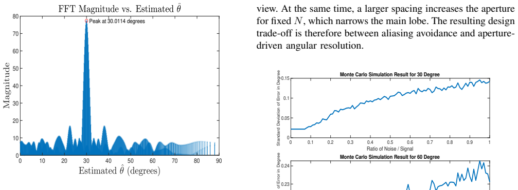
An FFT-based direction-of-arrival and range-estimation framework for a monostatic uniform linear array operating at 77 GHz is presented. A narrowband sinusoidal waveform is used to derive the spatial phase model, determine an aliasing-free inter-element spacing, and select the aperture required to obtain a boresight angular resolution of 2 degree. The resulting design uses an element spacing of 0.97 mm and 58 antenna elements, corresponding to an aperture length of 56.42 mm. Numerical results show accurate angular estimation for a single target at 30 degree and for multiple simultaneous targets. The analysis is further extended to two-dimensional localization by replacing the narrowband wave
What carries the argument
FFT applied to the spatial phase samples collected across the 58-element array, converting phase-progression patterns into distinct spectral peaks at the true target angles.
If this is right
- The 58-element design delivers 2 degree angular resolution at boresight.
- A 1 GHz sinc waveform on the same array yields approximately 0.15 m range resolution.
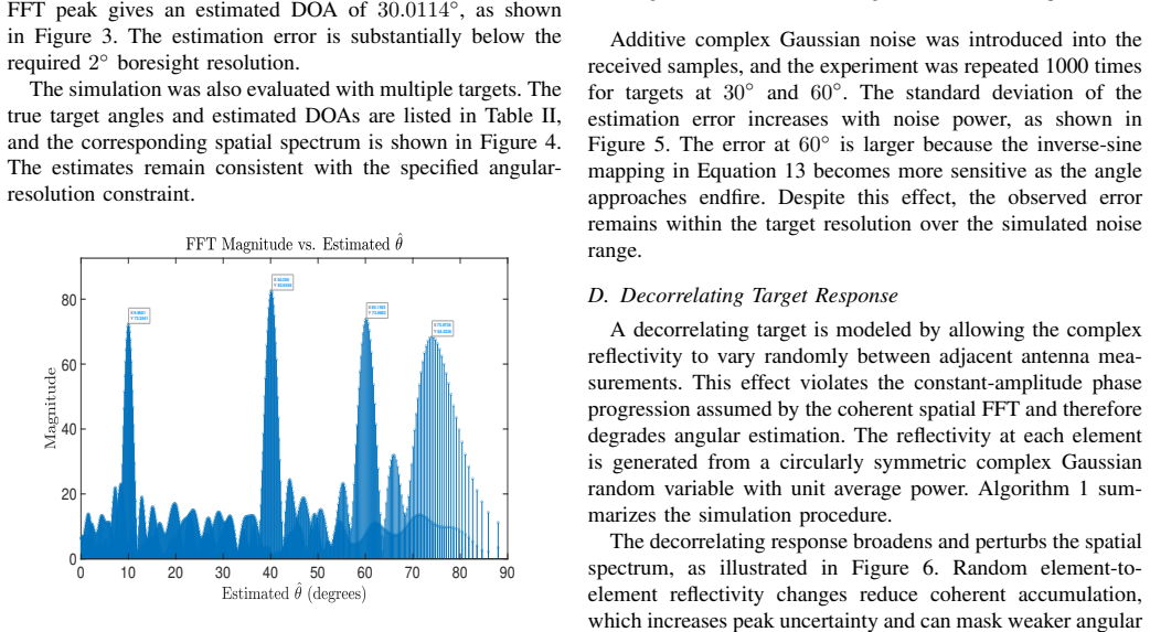
- Additive complex Gaussian noise, larger element spacing, and target decorrelation each shift or broaden the DOA spectral peaks in measurable ways.
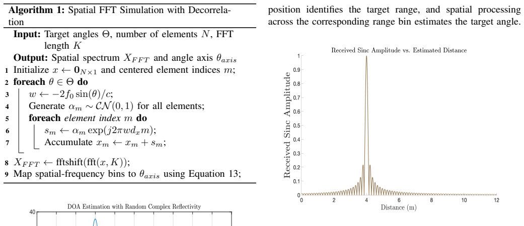
- Multiple targets produce separate, identifiable peaks when their angles differ sufficiently.
Where Pith is reading between the lines
- Real-world tests could check whether the predicted peaks survive indoor multipath or mutual coupling between elements.
- The same phase-model approach might be reused at other carrier frequencies by simply rescaling the element spacing to maintain the alias-free condition.
- Integrating Doppler processing on successive pulses could add velocity estimation without changing the spatial FFT step.
- The 0.15 m range cell size suggests the method could support coarse mapping of extended objects such as vehicles.
Load-bearing premise
The narrowband far-field spatial phase model derived from the sinusoidal waveform remains valid for the chosen 0.97 mm spacing and 58-element aperture, with no significant near-field effects, multipath, or hardware imperfections altering the FFT peaks.
What would settle it
An experiment that places a single known target at 30 degrees in front of the 58-element array and measures whether the dominant FFT peak falls more than one bin away from the predicted location.
Figures

read the original abstract
An FFT-based direction-of-arrival (DOA) and range-estimation framework for a monostatic uniform linear array (ULA) operating at 77 GHz is presented. A narrowband sinusoidal waveform is used to derive the spatial phase model, determine an aliasing-free inter-element spacing, and select the aperture required to obtain a boresight angular resolution of 2 degree. The resulting design uses an element spacing of 0.97 mm and 58 antenna elements, corresponding to an aperture length of 56.42 mm. Numerical results show accurate angular estimation for a single target at 30 degree and for multiple simultaneous targets. The analysis is further extended to two-dimensional localization by replacing the narrowband waveform with a 1 GHz sinc-modulated signal, which provides an approximate range resolution of 0.15 m. Additional simulations quantify the effects of additive complex Gaussian noise, increased antenna spacing, and target decorrelation on the DOA response.
Editorial analysis
A structured set of objections, weighed in public.
Referee Report
Summary. The manuscript presents an FFT-based framework for joint DOA and range estimation with a 77 GHz monostatic ULA. A narrowband sinusoidal waveform is used to derive an aliasing-free inter-element spacing of 0.97 mm and select a 58-element aperture of 56.42 mm for 2° boresight resolution. Numerical simulations demonstrate accurate single-target (30°) and multi-target angular estimation; the approach is extended to joint range-angle localization by substituting a 1 GHz sinc waveform (0.15 m range resolution). Additional simulations examine additive complex Gaussian noise, increased spacing, and target decorrelation.
Significance. If the far-field narrowband model remains valid, the work supplies a low-complexity FFT pipeline for mmWave radar that directly yields both angle and range from the same array. The explicit design formulas for spacing and aperture, together with the noise/decorrelaton test suite, constitute a practical contribution. The simulations are a strength in that they quantify performance degradation under realistic impairments rather than claiming ideal conditions only.
major comments (2)
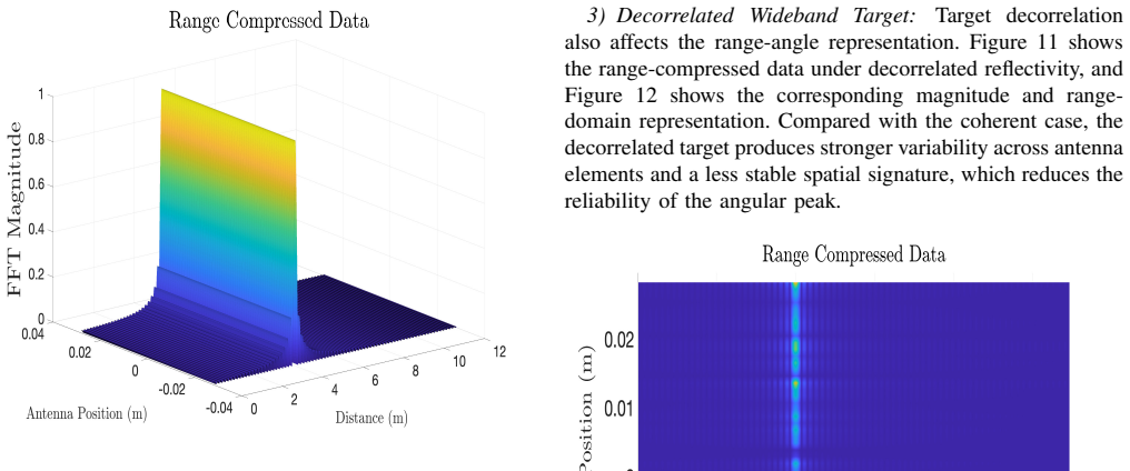
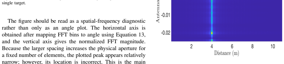
- [Numerical results] The numerical results section reports accurate FFT peaks for the chosen 0.97 mm / 58-element geometry but does not state the simulated target range(s). At 77 GHz the 56.42 mm aperture produces a Fraunhofer distance of ~1.63 m; any target inside this boundary violates the plane-wave assumption underlying the spatial phase model (derived in the narrowband section) and can shift or broaden the observed peaks. This directly affects the central accuracy claims.
- [Two-dimensional localization extension] The wideband extension replaces the sinusoid with a 1 GHz sinc waveform for range estimation but retains the same spatial phase model without re-derivation or validation. Range-angle coupling across the 58 elements is therefore unexamined and could degrade the joint localization performance reported in that section.
minor comments (2)
- The abstract states that 'increased antenna spacing' is simulated, yet the specific spacing values, the resulting aliasing threshold, and the corresponding figures are not cross-referenced in the text.
- Notation for the array response vector and the FFT bin indexing should be made consistent between the derivation and the simulation figures to avoid reader confusion.
Simulated Author's Rebuttal
We thank the referee for the constructive and detailed comments, which help clarify important aspects of the far-field assumption and the wideband extension. We address each major comment below and indicate planned revisions to improve the manuscript.
read point-by-point responses
-
Referee: [Numerical results] The numerical results section reports accurate FFT peaks for the chosen 0.97 mm / 58-element geometry but does not state the simulated target range(s). At 77 GHz the 56.42 mm aperture produces a Fraunhofer distance of ~1.63 m; any target inside this boundary violates the plane-wave assumption underlying the spatial phase model (derived in the narrowband section) and can shift or broaden the observed peaks. This directly affects the central accuracy claims.
Authors: We agree that the absence of explicit target ranges leaves the far-field validation incomplete. The simulations underlying the reported FFT peaks were performed with targets placed at distances satisfying the Fraunhofer criterion (greater than ~1.63 m). We will revise the Numerical Results section to state the specific ranges employed and add a short verification that the plane-wave model remains valid, thereby directly addressing the concern about potential peak shifts or broadening. revision: yes
-
Referee: [Two-dimensional localization extension] The wideband extension replaces the sinusoid with a 1 GHz sinc waveform for range estimation but retains the same spatial phase model without re-derivation or validation. Range-angle coupling across the 58 elements is therefore unexamined and could degrade the joint localization performance reported in that section.
Authors: The spatial phase model is derived under the narrowband approximation at the 77 GHz carrier; the 1 GHz bandwidth corresponds to a fractional bandwidth of only ~1.3 %, which supports retaining the same array response for the joint estimation. We nevertheless recognize that range-angle coupling merits explicit discussion. In the revision we will add a paragraph examining the validity of the approximation for the reported sinc-based range estimation and its implications for the observed localization performance. revision: partial
Circularity Check
No significant circularity; standard array formulas and direct simulation
full rationale
The paper derives the spatial phase model directly from the narrowband sinusoidal waveform under far-field plane-wave assumptions, then computes inter-element spacing (to avoid aliasing) and aperture length (for 2° resolution) using standard wavelength-based formulas at 77 GHz. These are not fitted to any outputs. Numerical results are generated by applying the model in simulation; the sinc-waveform extension for range is a direct substitution without re-derivation or parameter fitting. No self-citations, uniqueness theorems, or ansatzes are invoked. The derivation chain is self-contained against external benchmarks and does not reduce any claimed result to its inputs by construction.
Axiom & Free-Parameter Ledger
free parameters (1)
- Element count and aperture length
axioms (1)
- domain assumption Narrowband far-field assumption produces a linear spatial phase progression across the ULA that FFT can resolve without aliasing when spacing is below lambda/2.
Reference graph
Works this paper leans on
-
[1]
C. A. Balanis,Antenna Theory: Analysis and Design, 4th ed. Hoboken, NJ, USA: John Wiley & Sons, 2016
2016
-
[2]
D. H. Johnson and D. E. Dudgeon,Array Signal Processing: Concepts and Techniques. Englewood Cliffs, NJ, USA: Prentice Hall, 1993
1993
-
[3]
H. L. Van Trees,Optimum Array Processing. New York, NY , USA: Wiley-Interscience, 2002
2002
-
[4]
Multiple emitter location and signal parameter estima- tion,
R. O. Schmidt, “Multiple emitter location and signal parameter estima- tion,”IEEE Transactions on Antennas and Propagation, vol. 34, no. 3, pp. 276–280, 1986
1986
-
[5]
ESPRIT–estimation of signal parameters via ro- tational invariance techniques,
R. Roy and T. Kailath, “ESPRIT–estimation of signal parameters via ro- tational invariance techniques,”IEEE Transactions on Acoustics, Speech, and Signal Processing, vol. 37, no. 7, pp. 984–995, 1989
1989
-
[6]
Two decades of array signal processing research: the parametric approach,
H. Krim and M. Viberg, “Two decades of array signal processing research: the parametric approach,”IEEE Signal Processing Magazine, vol. 13, no. 4, pp. 67–94, 1996
1996
-
[7]
Stoica and R
P. Stoica and R. L. Moses,Spectral Analysis of Signals. Upper Saddle River, NJ, USA: Prentice Hall, 2005
2005
-
[8]
High-resolution frequency-wavenumber spectrum analysis,
J. Capon, “High-resolution frequency-wavenumber spectrum analysis,” Proceedings of the IEEE, vol. 57, no. 8, pp. 1408–1418, 1969
1969
-
[9]
Beamforming: A versatile approach to spatial filtering,
B. D. Van Veen and K. M. Buckley, “Beamforming: A versatile approach to spatial filtering,”IEEE ASSP Magazine, vol. 5, no. 2, pp. 4–24, 1988
1988
-
[10]
Detection of signals by information theoretic criteria,
M. Wax and T. Kailath, “Detection of signals by information theoretic criteria,”IEEE Transactions on Acoustics, Speech, and Signal Process- ing, vol. 33, no. 2, pp. 387–392, 1985
1985
-
[11]
Application of antenna arrays to mobile communications. part II: Beam-forming and direction-of-arrival considerations,
L. C. Godara, “Application of antenna arrays to mobile communications. part II: Beam-forming and direction-of-arrival considerations,”Proceed- ings of the IEEE, vol. 85, no. 8, pp. 1195–1245, 1997
1997
-
[12]
M. A. Richards,Fundamentals of Radar Signal Processing, 2nd ed. New York, NY , USA: McGraw-Hill Education, 2014
2014
-
[13]
M. I. Skolnik, Ed.,Radar Handbook, 3rd ed. New York, NY , USA: McGraw-Hill, 2008
2008
-
[14]
Millimeter-wave technology for automotive radar sensors in the 77 GHz frequency band,
J. Hasch, E. Topak, R. Schnabel, T. Zwick, R. Weigel, and C. Wald- schmidt, “Millimeter-wave technology for automotive radar sensors in the 77 GHz frequency band,”IEEE Transactions on Microwave Theory and Techniques, vol. 60, no. 3, pp. 845–860, 2012
2012
-
[15]
Li and P
J. Li and P. Stoica,MIMO Radar Signal Processing. Hoboken, NJ, USA: John Wiley & Sons, 2008
2008
-
[16]
Monti Guarnieri,Electromagnetic Imaging, 1st ed
A. Monti Guarnieri,Electromagnetic Imaging, 1st ed. Politecnico di Milano, 2015
2015
-
[17]
Ferretti, A
A. Ferretti, A. Monti-Guarnieri, C. Prati, F. Rocca, and D. Massonnet, InSAR Principles: Guidelines for SAR Interferometry Processing and Interpretation, European Space Agency, 2007
2007
discussion (0)
Sign in with ORCID, Apple, or X to comment. Anyone can read and Pith papers without signing in.