REVIEW 3 major objections 4 minor 115 references
Development of large Micromegas readout planes for experiments searching for rare events
T0 review · 3 major / 4 minor · reviewed 2026-08-11 · deepseek-v4-flash
Pith's one-line read This thesis shows that large, low-background readout planes for rare-event searches can be built by tiling modular microbulk Micromegas detectors, and demonstrates the approach with a seven-module prototype plane and a full-size 52-module…
desk verdict A technically honest thesis with two solid new measurements, but the scalability headline is only partially supported: the 7-module prototype was analyzed in selected regions and the 52-module plane uses an untested, different Micromegas technology. read the letter →
The pith
A machine-rendered reading of the paper's core claim, the machinery that carries it, and where it could break.
The reading
What carries the argument
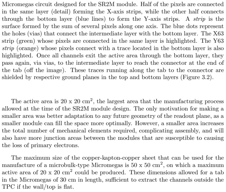
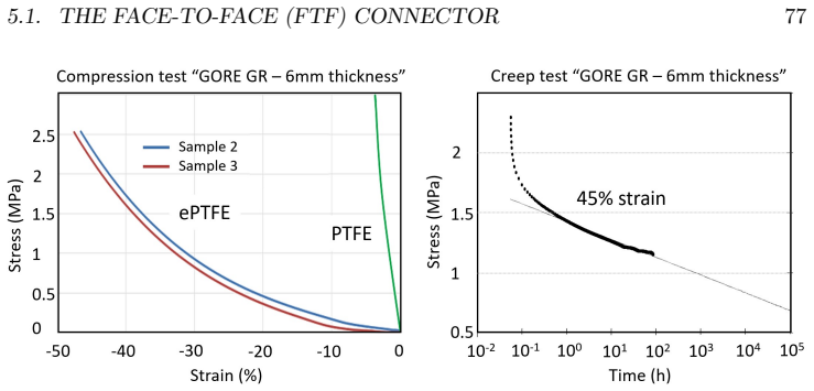
The load-bearing element is the modular readout tile: a microbulk Micromegas circuit — a copper-polyimide laminate with a thin mesh separated from a segmented anode by a roughly 50-micron amplification gap — fixed to a copper support. Around each active area sit rim electrodes that steer the drift electric field lines so that primary electrons are collected even at the gaps between tiles; simulations show collection efficiencies up to 99.94% with sufficient rim voltages. A second key piece is the face-to-face (FtF) connector, two flexible circuits pressed together through expanded PTFE so that pads make contact without a commercial high-radioactivity connector inside the detector; 804 contacts survived eleven months of temperature cycling with no loss of continuity. For the dark matter detector, the additional mechanism is a GEM (a gas electron multiplier foil) placed above the Micromegas to pre-amplify the charge and thereby reduce the energy threshold.
What would settle it
Take the installed 25 x 25 cm pixelated Micromegas and the 2 cm single-pixel Micromegas used for laboratory calibration, place both in the same gas mixture (Ar + 1% isobutane, 1.5 bar) with the same drift and amplification fields, and compare gain curves and energy resolution at the 22 keV line of a 109Cd source; if the large detector still shows 23-29% FWHM while the small one shows 11-13% FWHM under identical conditions, the transferability assumption is falsified.
Extended reading notes
Core claim
The central claim is that microbulk Micromegas readout planes can be scaled to the sizes required by rare-event experiments without losing their advantage in radioactivity or energy resolution. The paper establishes this through the SR2M module: a 20 x 20 cm2 microbulk circuit mounted on a copper support with a tab that exits the chamber, an electron reintegration system of inner and outer rims that steer drift-field lines away from inter-module dead zones, and, in the second version, a radiopure face-to-face connector that replaces high-radioactivity commercial connectors inside the detector. A seven-module readout plane was commissioned with radioactive sources and achieved useful electron transmission, gain, and energy resolution, and a full-size plane of 52 modules was assembled for the finalized 140 kg double beta decay detector. For the WIMP-search detector, the thesis reports that a 25 x 25 cm2 microbulk Micromegas installed in a 10-bar TPC reproduced the expected gain curve, reached voltages close to the expected maximum before sparking, and achieved a 1–1.5 keV energy threshold, with a GEM-Micromegas system and a new low-radioactivity Micromegas designed to push that threshold lower. A separate demonstrator, AlphaCAMM, applies the same readout technology to detect surface alpha particles.
Load-bearing premise
The load-bearing premise, stated in Section 7.2, is that the small Micromegas used for laboratory calibration behaves like the large pixelated one installed in the detector despite a difference in amplification-hole size, and if that small-to-large transfer fails, the chosen operating voltages and expected resolutions are unsupported.
Editorial extensions
If this is right
- A readout plane for a ton-scale double beta decay TPC can be built by tiling 52 SR2M modules, reaching a diameter of nearly two meters with signals extracted through a small number of flanges.
- The electron reintegration system recovers almost all primary electrons that would otherwise be lost in dead zones between modules: simulations reach 99.94% efficiency, and measurements with the internal rim show only a small loss in the last two millimeters at a modest rim voltage.
- Eliminating the external rim and using the face-to-face connector reduced the fraction of dead channels in a seven-module plane from 9.2% to 1.1%, with connection losses removed entirely.
- A GEM pre-amplification stage above a Micromegas can lower the energy threshold of a high-pressure gas TPC, which is the path to sensitivity for low-mass WIMPs.
- The same readout technology, packaged as AlphaCAMM, provides a low-background detector for surface alpha contamination on detector materials.
Reading between the lines
- If the small-to-large transferability assumption holds for the current TREX-DM plane, the same characterization method could be extended to other gas mixtures and pressures, letting future large planes be tuned without building a new prototype for every operating point.
- The tiling concept is not tied to microbulk Micromegas: the SR2M-v2 modules already use a thermally bonded mesh-and-circuit construction, suggesting the module design could accommodate whatever radiopure micropattern technology matures next.
- The edge-loss behaviour measured with the internal rim implies that the optimal plane-level operating point is a trade-off between collecting charge at the boundaries and preserving track reconstruction in the last millimetres; a dedicated study of this trade-off would determine whether higher rim voltages are worth applying.
- AlphaCAMM's emanation-based background model could be turned into a standard screening tool for radiopure materials, extending beyond the specific experiment that motivated it.
Editorial analysis
A structured set of objections, weighed in public.
Referee Report
Summary. This doctoral thesis reports the development of tiled microbulk Micromegas readout planes for two rare-event gaseous TPC experiments. Part I presents the Scalable Radiopure Readout Module (SR2M) for PandaX-III: the module design, the electron reintegration system, a custom feedthrough, a new Face-to-Face (FtF) connector, and two module versions. Commissioning results are shown for a single module and for a 7-module plane; the construction of a 52-module full-size plane is reported. Part II describes the commissioning and optimization of the TREX-DM detector, including a new 25x25 cm² Micromegas, background reduction, energy-threshold studies, and a GEM-Micromegas pre-amplification stage. Part III covers the design, background model, and commissioning of AlphaCAMM, a surface-alpha detector. The overarching claim is that tiling SR2M modules enables the construction of large readout planes for low-background rare-event experiments.
Significance. If the scalability claim is fully established, this work addresses a genuine bottleneck for ton-scale gaseous TPCs in neutrinoless double-beta decay and dark-matter searches. The engineering contributions are concrete and in several places well validated: the FtF connector is supported by an independent FEM-versus-Navier comparison and by 804 direct resistance measurements over eleven months, and the ERS behaviour is studied with Garfield++ simulations. The thesis is also commendably honest about many limitations, including defective channels, manufacturing errors, and the untested status of the full-size plane. However, the central scalability claim is only partially verified: the 7-module plane is characterized with selectively chosen regions and has 9.2% defective channels, while the 52-module full-size plane uses a different Micromegas technology whose performance is not presented. The significance of the work as a standalone demonstration of large-plane usability is therefore currently limited.
major comments (3)
- [§4.4] The 7-module plane is the main experimental evidence for the scalability claim, but its full-plane response is not quantified. The text states that the spectra in Fig. 4.11 were obtained by 'strategically selecting areas with fewer defective channels,' and Fig. 4.12 reports 9.2% defective channels. The manufacturing error that left no amplification holes at the module edges, also noted in this section, further reduces the active area and prevented experimental verification of the external rim. Please provide a full-plane efficiency map, the fraction of active area lost to dead zones and defective channels, and the energy resolution obtained with the complete plane, or explicitly restrict the scalability claim to the mechanical tiling rather than to the usable performance of a tiled readout plane.
- [§5.2.4] The construction of the 52-module full-size readout plane is reported, but this plane is fabricated with a different Micromegas technology (thermal bonding at USTC [55]) whose development and testing are 'outside the scope of this thesis.' No gain, energy resolution, dead-channel fraction, or tiling-efficiency measurement for this plane is presented. The central scalability claim for the final PandaX-III detector therefore extrapolates from the 7-module microbulk prototype to an untested technology. Please either provide the surface-test results for the 52-module plane or clearly state in the abstract and conclusions that the performance of the full-size plane remains unvalidated.
- [§7.2] The TREX-DM operating point is selected using systematic measurements from a 2 cm single-pixel microbulk Micromegas with 55 µm amplification holes [77], while the installed device is a 25x25 cm² pixelated Micromegas with 50 µm holes. The text explicitly assumes 'that the response and behavior of both are similar,' but the measured energy resolution in TREX-DM (23–29% FWHM) is substantially worse than the 11–13% FWHM reported for the small prototypes. This large discrepancy indicates that the transferability assumption is not yet established and is load-bearing for the chosen gain, threshold, and expected background discrimination. Please quantify the sources of the resolution degradation and validate the operating point directly on the large device, or reframe the assumption as an open item requiring dedicated measurement.
minor comments (4)
- [§5.1.3] In Eqs. (5.1) and (5.2), the notation for the standard deviation is confusing: σ_i(R) is written as a sum over j, but the index i appears both as the label of the per-channel quantity and as the summation index in Eq. (5.1). Please use distinct indices for the channel label and the measurement index.
- [§7.2] The sentence comparing energy resolutions is incomplete: the text reads '11−13' and stops abruptly, presumably missing 'FWHM.' Please correct the typo.
- [Chapter headings] Several chapter and section titles appear in Spanish (e.g., 'Sistemas de apoyo...' in the table of contents and 'Necesidad de un detector de partículas alfa superficiales' in Chapter 10) while the rest of the text is in English. Please unify the language throughout.
- [General] The thesis introduces many abbreviations (ERS, FtF, SR2M, FEC, TCM, MCA) without a central list of acronyms. Adding a glossary would improve readability for a journal-style audience.
Circularity Check
No significant circularity: the scalability, FtF-connector, and internal-rim claims rest on direct measurements; prior self-characterizations are used as stated assumptions and consistency checks, not as fitted inputs relabeled as predictions.
full rationale
This thesis reports a development chain (SR2M tiling for PandaX-III, TREX-DM readout optimization, AlphaCAMM) in which each load-bearing claim is backed by direct measurement rather than by a fitted constant relabeled as a prediction. The FtF connector, central to the scalability claim, is validated two independent ways: an FEM stress analysis cross-checked against the analytical Navier plate solution (Sec. 5.1.2), and a dedicated test bench in which all 804 connectors across three assemblies kept continuity through six temperature cycles, with 5628 resistance measurements (Sec. 5.1.3). The internal-rim (ERS) collection efficiency is demonstrated empirically in Fig. 5.16, which shows charge loss dropping from ~100% to ~15% in the last 2 mm when the rim is biased 80 V above the mesh, and the residual loss is openly quantified. The 7-module readout plane is characterized with radioactive sources (Sec. 4.4), and the thesis discloses both the 9.2% defective-channel fraction and that the figure-4.11 spectra were selected from regions with fewer defective channels, so no selective result is disguised as a full-plane prediction. In the TREX-DM part, operating points are carried over from the group's prior systematic characterization of small Micromegas ([77], Sec. 7.2) under an explicitly stated similarity assumption about hole size; the subsequent calibrations are measured, and the observed 23-29% FWHM resolution is reported as worse than the small-prototype 11-13%, so the assumption is not used to manufacture agreement. Use of the group's REST-for-Physics framework for both simulation and analysis is a code-based, falsifiable pipeline and is not used to force spectral agreement; simulated peak positions are physical (59.5 keV and xenon escape peaks). No uniqueness theorem from the authors' earlier work is invoked to forbid alternatives, and no parameter fit is relabeled as a prediction. The main risks, correctly identified in the manuscript, are that the full-size 52-module plane uses a different thermal-bonding Micromegas technology whose testing is outside the thesis scope (Sec. 5.2.4), and that small-area-to-large-area transfer is assumed (Sec. 7.2); these are correctness/extrapolation risks, not circular derivations.
Assumptions & free parameters
free parameters (2)
- SR2M strip width =
3.09 mm
- Internal rim bias above mesh =
+80 V with mesh at 300 V
assumptions (3)
- domain assumption Primary electrons in the conversion volume follow electric field lines in the ERS design simulations.
- domain assumption Small-area single-pixel microbulk Micromegas characterization transfers to large-area pixelated Micromegas.
- standard math Standard gas detector relations, including ionization yield W, Fano factor, drift velocity, and diffusion, apply to the mixtures used.
Cite this review
Pith. "Pith review of Development of large Micromegas readout planes for experiments searching for rare events." pith.science (2026). https://pith.science/paper/XBXD24EN
@misc{pith2026241216313,
  author       = {Pith},
  title        = {Pith review of: Development of large Micromegas readout planes for experiments searching for rare events},
  year         = {2026},
  howpublished = {\url{https://pith.science/paper/XBXD24EN}},
  note         = {Machine review of arXiv:2412.16313}
}
read the original abstract
The use of Time Projection Chambers (TPCs) in particle physics experiments has been growing since their invention, reaching sizes equivalent to buildings (ALICE or ATLAS at CERN). However, their application in another class of experiments, commonly referred to as rare event experiments, has been more recent. This work focuses on two such experiments aimed at searching for rare events: the search for neutrinoless double beta decay (PandaX-III experiment) and the search for WIMPs (TREX-DM experiment). Both utilize a large-sized gaseous TPC, necessitating that the corresponding readout plane is also large. Both also employ microbulk Micromegas readout planes. This technology has become established in recent years and is continuously improving. Due to the size limitation during manufacturing and the concurrent increase in the size of double beta experiments, there arose a need to develop a tiled readout plane, using a mosaic of modules with microbulk Micromegas, conforming the first part of this thesis, in the context of the PandaX-III experiment. The second part, featuring a single readout plane of 25 x 25 cm2 installed in TREX-DM, focuses on the specifications that define a Micromegas and its response in a high-pressure gaseous detector. Additionally, during the work on TREX-DM, the need to reduce the energy threshold of the experiment emerged, leading to the development of another composite readout plane, the GEM-Micromegas system, in which a GEM specifically manufactured for this system was installed above the Micromegas. Finally, leveraging the development of the Micromegas for TREX-DM, a new gaseous detector for the detection of surface alpha particles, called AlphaCAMM, is planned, designed, and implemented, addressing all the requirements of a low-background detector with a projection beyond the TREX-DM experiment.
Figures


Figures from the paper (165 more)









Reference graph
Works this paper leans on
-
[55]
A thermal bonding method for manufacturing Micromegas detectors
Jianxin Feng, Zhiyong Zhang, Jianbei Liu, Binbin Qi, Anqi Wang, Ming Shao, and Yi Zhou. A thermal bonding method for manufacturing Micromegas detectors. Nuclear Instruments and Methods in Physics Research Section A: Accelerators, Spectrometers, Detectors and Associated Equipment, 989:164958, 2 2021
work page 2021
-
[77]
F. J. Iguaz, T. Dafni, C. Canellas, J. F. Castel, S. Cebri´ an, J. G. Garza, I. G. Irastorza, G. Luz´ on, H. Mirallas, and E. Ruiz-Ch´ oliz. Microbulk Micromegas in non-flammable mixtures of argon and neon at high pressure. Journal of Instrumentation, 17(07):P07032, 7 2022
work page 2022
-
[1]
Marx and David R
Jay N. Marx and David R. Nygren. The Time Projection Chamber. Physics Today, 31(10):46–53, 10 1978
1978
-
[2]
Charpak, R
G. Charpak, R. Bouclier, T. Bressani, J. Favier, and ˇC Zupanˇ ciˇ c. The use of multiwire proportional counters to select and localize charged particles. Nuclear Instruments and Methods , 62(3):262–268, 7 1968
1968
-
[3]
A. H. Walenta, J. Heintze, and B. Sch¨ urlein. The multiwire drift chamber a new type of proportional wire chamber. Nuclear Instruments and Methods , 92(3):373–380, 4 1971
1971
-
[5]
National Institute of Standards and Technology
-
[6]
Adams et al
C. Adams et al. Reconstruction and Measurement of O(100) MeV Energy Electromagnetic Activity from π0 → γγ Decays in the MicroBooNE LArTPC. JINST, 15(02), 2 2020
2020
-
[7]
A. Oed. Position-sensitive detector with microstrip anode for electron multiplication with gases. Nuclear Instruments and Methods in Physics Research Section A: Accelerators, Spectrometers, Detectors and Associated Equipment, 263(2-3):351–359, 1 1988
1988
Show all 115 references
-
[8]
F. Sauli. GEM: A new concept for electron amplification in gas detectors. Nuclear Instruments and Methods in Physics Research Section A: Accelerators, Spectrometers, Detectors and Associated Equipment, 386(2-3):531–534, 2 1997
1997
-
[9]
Giomataris, Ph
Y. Giomataris, Ph. Rebourgeard, J.P. Robert, and G. Charpak. MICROMEGAS: a high-granularity position-sensitive gaseous detector for high particle-flux environments. Nuclear Instruments and Methods in Physics Research Section A: Accelerators, Spectrometers, Detectors and Associ...
1996
-
[10]
Giomataris, R
I. Giomataris, R. De Oliveira, S. Andriamonje, S. Aune, G. Charpak, P. Colas, G. Fanourakis, E. Ferrer, A. Giganon, Ph Rebourgeard, and P. Salin. Micromegas in a bulk. Nuclear Instruments and Methods in Physics Research Section A: Accelerators, Spectrometers, Detectors and Ass...
2006
-
[11]
Andriamonje, D
S. Andriamonje, D. Attie, E. Berthoumieux, M. Calviani, P. Colas, T. Dafni, G. Fanourakis, E. Ferrer-Ribas, J. Galan, T. Geralis, A. Giganon, I. Giomataris, A. Gris, C. Guerrero Sanchez, F. Gunsing, J. Iguaz, I. Irastorza, R. De Oliveira, T. Papaevangelou, J. Ruz, I. Savvidis,...
2010
-
[12]
Iguaz, E
J. Iguaz, E. Ferrer-Ribas, A. Giganon, and I. Giomataris. Characterization of microbulk detectors in argon- and neon-based mixtures. Journal of Instrumentation, 7(04):P04007, 4 2012. BIBLIOGRAPHY 239
2012
-
[13]
Anvar, P
S. Anvar, P. Baron, B. Blank, J. Chavas, E. Delagnes, F. Druillole, P. Hellmuth, L. Nalpas, J.L. Pedroza, J. Pibernat, E. Pollacco, A. Rebii, and N. Usher. AGET, the GET front-end ASIC, for the readout of the Time Projection Chambers used in nuclear physic experiments. In 2011...
2011
-
[14]
AFTER, an ASIC for the Readout of the Large T2K Time Projection Chambers
Pascal Baron, Denis Calvet, Eric Delagnes, Xavier de la Broise, Alain Delbart, Fr´Ed´Eric Druillole, Eduardo Mazzucato, Estelle Monmarthe, FranC ¸ ois Pierre, and Marco Zito. AFTER, an ASIC for the Readout of the Large T2K Time Projection Chambers. IEEE Transactions on Nuclear...
2008
-
[15]
Konrad Altenm¨ uller, Susana Cebri´ an, Theopisti Dafni, David D ´ ıez-Ib´ a˜ nez, Javier Gal´ an, Javier Galindo, Juan Antonio Garc ´ ıa, Igor G. Irastorza, Gloria Luz´ on, Cristina Margalejo, Hector Mirallas, Luis Obis, Oscar P´ erez, Ke Han, Kaixiang Ni, Yann Bedfer, Barbar...
2022
-
[16]
ROOT - Data Analysis Framework
-
[17]
Fukuda et al
Y. Fukuda et al. Solar 8B and hep Neutrino Measurements from 1258 Days of Super-Kamiokande Data. Physical Review Letters, 86(25):5651, 6 2001
2001
-
[18]
Q. R. Ahmad et al. Direct Evidence for Neutrino Flavor Transformation from Neutral-Current Interactions in the Sudbury Neutrino Observatory. Physical Review Letters, 89(1):011301, 6 2002
2002
-
[19]
C. K. Jung, T. Kajita, T. Mann, and C. McGrew. OSCILLATIONS OF ATMOSPHERIC NEUTRINOS. https://doi.org/10.1146/annurev.nucl.51.101701.132421, 51(1):451–488, 11 2003
2003
-
[20]
Araki, K
T. Araki, K. Eguchi, S. Enomoto, K. Furuno, K. Ichimura, H. Ikeda, K. Inoue, K. Ishihara, T. Iwamoto, T. Kawashima, Y. Kishimoto, M. Koga, Y. Koseki, T. Maeda, T. Mitsui, M. Motoki, K. Nakajima, H. Ogawa, K. Owada, J. S. Ricol, I. Shimizu, J. Shirai, F. Suekane, A. Suzuki, K. ...
2005
-
[21]
Elliott and Petr Vogel
Steven R. Elliott and Petr Vogel. DOUBLE BETA DECAY. https://doi.org/10.1146/annurev.nucl.52.050102.090641, 52:115–151, 11 2003
2003
-
[22]
Dafni, S
T. Dafni, S. Aune, J. Castel, S. Cebri´ an, G. Fanourakis, E. Ferrer-Ribas, D. Fortu˜ no, J. Gal´ an, J. A. Garc ´ ıa, A. Gardikiotis, J. G. Garza, T. Geralis, I. Giomataris, H. G´ omez, D. C. Herrera, F. J. Iguaz, I. G. Irastorza, G. Luz´ on, J. P. Mols, A. Ortiz, T. Papaevan...
2012
-
[23]
Alexopoulos, A
T. Alexopoulos, A. A. Altintas, M. Alviggi, M. Arik, S. A. Cetin, V. Chernyatine, E. Cheu, D. Della Volpe, M. Dris, D. Fassouliotis, E. N. Gazis, R. Giordano, V. Gratchev, L. Guan, P. Iengo, P. Ioannou, C. Li, K. Johns, V. Kaushik, A. Khodinov, C. Kourkoumelis, S. Maltezos, K....
2010
-
[24]
Alexeev, R
M. Alexeev, R. Birsa, F. Bradamante, A. Bressan, M. B¨ uchele, M. Chiosso, P. Ciliberti, S. Dalla Torre, S. Dasgupta, O. Denisov, V. Duic, M. Finger, M. Finger, H. Fischer, M. Giorgi, B. Gobbo, M. Gregori, F. Herrmann, K. K¨ onigsmann, S. Levorato, A. Maggiora, A. Martin, G. M...
2013
-
[25]
Anastassopoulos, S
V. Anastassopoulos, S. Aune, K. Barth, A. Belov, H. Br¨ auninger, G. Cantatore, J. M. Carmona, J. F. Castel, S. A. Cetin, F. Christensen, J. I. Collar, T. Dafni, M. Davenport, T. A. Decker, A. Dermenev, K. Desch, C. Eleftheriadis, G. Fanourakis, E. Ferrer-Ribas, H. Fischer, J....
2017
-
[26]
Abe and T2K collaboration
K. Abe and T2K collaboration. The T2K experiment. Nuclear Instruments and Methods in Physics Research Section A: Accelerators, Spectrometers, Detectors and Associated Equipment , 659(1):106–135, 12 2011
2011
-
[27]
Cebri´ an, T
S. Cebri´ an, T. Dafni, E. Ferrer-Ribas, J. Gal´ an, I. Giomataris, H. G´ omez, F. J. Iguaz, I. G. Irastorza, G. Luz´ on, R. De Oliveira, A. Rodr ´ ıguez, L. Segu ´ ı, A. Tom´ as, and J. A. Villar. Radiopurity of micromegas readout planes. Astroparticle Physics, 34(6):354–359, 1 2011
2011
-
[28]
Castel, S
J. Castel, S. Cebrian, I. Coarasa, T. Dafni, J. Galan, F. J. Iguaz, I. G. Irastorza, G. Luzon, H. Mirallas, A. Ortiz de Solorzano, and E. Ruiz-Choliz. Background assessment for the TREX dark matter experiment. The European Physical Journal C 2019 79:9 , 79(9):1–19, 9 2019
2019
-
[29]
Description and commissioning of NEXT-MM prototype: first results from operation in a Xenon-Trimethylamine gas mixture
V ´Alvarez, F Aznar, F I G M Borges, D Calvet, S C´ arcel, J Castel, S Cebri´ an, A Cervera, C A N Conde, T Dafni, T H V T Dias, J D ´ ıaz, F Druillole, M Egorov, R Esteve, P Evtoukhovitch, L M P Fernandes, P Ferrario, A L Ferreira, E Ferrer-Ribas, E D C Freitas, V M Gehman, A...
2014
-
[30]
´Alvarez, F
V. ´Alvarez, F. I.G.M. Borges, S. C´ arcel, J. Castel, S. Cebri´ an, A. Cervera, C. A.N. Conde, T. Dafni, T. H.V.T. Dias, J. D ´ ıaz, M. Egorov, R. Esteve, P. Evtoukhovitch, L. M.P. Fernandes, P. Ferrario, A. L. Ferreira, E. D.C. Freitas, V. M. Gehman, A. Gil, A. Goldschmidt, ...
2014
-
[31]
F. J. Iguaz, J. G. Garza, F. Aznar, J. F. Castel, S. Cebri´ an, T. Dafni, J. A. Garc ´ ıa, I. G. Irastorza, A. Lagraba, G. Luz´ on, and A. Peir´ o. TREX-DM: a low-background Micromegas-based TPC for low-mass WIMP detection. The European Physical Journal C 2016 76:10 , 76(10):1...
2016
-
[32]
I. G. Irastorza, F. Aznar, J. Castel, S. Cebri´ an, T. Dafni, J. Gal´ an, J. A. Garcia, J. G. Garza, H. G´ omez, D. C. Herrera, F. J. Iguaz, G. Luzon, H. Mirallas, E. Ruiz, L. Segu ´ ı, and A. Tom´ as. Gaseous time projection chambers for rare event detection: results from the...
2016
-
[33]
Irastorza, F
I.G. Irastorza, F. Aznar, J. Castel, S. Cebri´ an, T. Dafni, J. Gal´ an, J.A. Garcia, J.G. Garza, H. G´ omez, D.C. Herrera, F.J. Iguaz, G. Luzon, H. Mirallas, E. Ruiz, L. Segu ´ ı, and A. Tom´ as. Gaseous time projection chambers for rare event detection: results from the T-RE...
2016
-
[34]
Khan, Neill Raper, Jian Tang, Wei Wang, Jia Ning Dong, Chang Qing Feng, Cheng Li, Jian Bei Liu, Shu Bin Liu, Xiao Lian Wang, Dan Yang Zhu, Juan F
Xun Chen, Chang Bo Fu, Javier Galan, Karl Giboni, Franco Giuliani, Ling Hui Gu, Ke Han, Xiang Dong Ji, Heng Lin, Jiang Lai Liu, Kai Xiang Ni, Hiroki Kusano, Xiang Xiang Ren, Shao Bo Wang, Yong Yang, Dan Zhang, Tao Zhang, Li Zhao, Xiang Ming Sun, Shou Yang Hu, Si Yu Jian, Xing ...
2017
-
[35]
Zhang, H
W. Zhang, H. Lin, Y. Liu, K. Han, K. Ni, S. Wang, W. Zhai, and on behalf of the PandaX-III Collaboration. Status and prospects of the PandaX-III experiment. Journal of Instrumentation , 18(12):C12001, 12 2023
2023
-
[36]
Aznar, J
F. Aznar, J. Castel, S. Cebri´ an, T. Dafni, A. Diago, J. A. Garc ´ ıa, J. G. Garza, H. G´ omez, D. Gonz´ alez-D ´ ıaz, D. C. Herrera, F. J. Iguaz, I. G. Irastorza, BIBLIOGRAPHY 243 G. Luz´ on, H. Mirallas, M. A. Oliv´ an, A. Ortiz De Sol´ orzano, P. Pons, A. Rodr ´ ıguez, E. ...
2013
-
[37]
Leo William R. Techniques for Nuclear and Particle Physics Experiments, Second Revised Edidtion, Springer-Verlag Berlin Heidelberg GmbH, ISBN 978-3-540-57280-0 ISBN 978-3-642-57920-2 (eBook),DOI 10.1007/978-3-642-57920-2. Springer-Verlag Berlin Heidelberg, 1994
-
[38]
J. Galan. Microbulk MicrOMEGAs for the search of 0 νββ of 136Xe in the PandaX-III experiment. Journal of Instrumentation , 11(04):P04024, 4 2016
2016
-
[39]
H. Lin, D. Calvet, L. Chen, X. Chen, T. Dafni, C. Fu, J. Galan, K. Han, S. Hu, Y. Huo, I. G. Irastorza, X. Ji, X. Li, X. Li, J. Liu, H. Mirallas, D. Neyret, K. Ni, H. Qiao, X. Ren, Sh Wang, Si Wang, Y. Yang, Y. Yuan, T. Zhang, and L. Zhao. Design and commissioning of a 600 L T...
2018
-
[40]
Diego Gonz´ alez-D ´ ıaz, V.´Alvarez, F. I.G. Borges, M. Camargo, S. C´ arcel, S. Cebri´ an, A. Cervera, C. A.N. Conde, T. Dafni, J. D ´ ıaz, R. Esteve, L. M.P. Fernandes, P. Ferrario, A. L. Ferreira, E. D.C. Freitas, V. M. Gehman, A. Goldschmidt, J. J. G´ omez-Cadenas, R. M. ...
2015
-
[41]
Galan, X
J. Galan, X. Chen, H. Du, C. Fu, K. Giboni, F. Giuliani, K. Han, B. Jiang, X. Ji, H. Lin, Y. Lin, J. Liu, K. Ni, X. Ren, S. Wang, S. Wu, C. Xie, Y. Yang, T. Zhang, L. Zhao, S. Aune, Y. Bedfer, E. Berthoumieux, D. Calvet, N. D’Hose, E. Ferrer-Ribas, F. Kunne, B. Manier, D. Neyr...
2020
-
[42]
Radiopurity control in the NEXT-100 double beta decay experiment: procedures and initial measurements
V ´Alvarez, I Bandac, A Bettini, F I G M Borges, S C´ arcel, J Castel, S Cebri´ an, A Cervera, C A N Conde, T Dafni, T H V T Dias, J D ´ ıaz, M Egorov, R Esteve, P Evtoukhovitch, L M P Fernandes, P Ferrario, A L Ferreira, E D C Freitas, V M Gehman, A Gil, A Goldschmidt, H G´ o...
2013
-
[43]
Elmer FEM – open source multiphysical simulation software
-
[44]
Summary of Properties, 2017
DuPont. Summary of Properties, 2017
2017
-
[45]
Drift and Diffusion of Electrons in Gases: A Compilation (With an Introduction to the Use of Computing Programs)
Anna Peisert and Fabio Sauli. Drift and Diffusion of Electrons in Gases: A Compilation (With an Introduction to the Use of Computing Programs). CERN 84-08 Experimental Physics Division , 1984
1984
-
[47]
Low Background Counting At SNOLAB
Ian Lawson and Bruce Cleveland. Low Background Counting At SNOLAB. AIP Conference Proceedings, 1338(1):68–77, 4 2011
2011
-
[48]
PandaX-III high pressure xenon TPC for Neutrinoless Double Beta Decay search
Shaobo Wang. PandaX-III high pressure xenon TPC for Neutrinoless Double Beta Decay search. Nuclear Instruments and Methods in Physics Research Section A: Accelerators, Spectrometers, Detectors and Associated Equipment , 958:162439, 4 2020
2020
-
[49]
Development of a Micromegas Time Projection Chamber in Xe-based Penning Mixtures for Rare Event Searches
Diana Carolina Herrera Mu˜ noz. Development of a Micromegas Time Projection Chamber in Xe-based Penning Mixtures for Rare Event Searches . PhD thesis, Universidad de Zaragoza, 2014
2014
-
[50]
Ruiz-Choliz, D
E. Ruiz-Choliz, D. Gonz´ alez-D ´ ıaz, A. Diago, J. Castel, T. Dafni, D. C. Herrera, F. J. Iguaz, I. G. Irastorza, G. Luz´ on, H. Mirallas, S ¸ahin, and R. Veenhof. Modelling the behaviour of microbulk Micromegas in xenon/trimethylamine gas. Nuclear Instruments and Methods in ...
2015
-
[51]
S. et al. Agostinelli. Geant4—a simulation toolkit. Nuclear Instruments and Methods in Physics Research Section A: Accelerators, Spectrometers, Detectors and Associated Equipment , 506(3):250–303, 7 2003. BIBLIOGRAPHY 245
2003
-
[52]
The TPC detector of PandaX-III Neutrinoless Double Beta Decay experiment
Zhou Huang and Guofang Shen. The TPC detector of PandaX-III Neutrinoless Double Beta Decay experiment. Journal of Instrumentation , 15(03):C03052, 3 2020
2020
-
[56]
Lobasenko
A. Lobasenko. Reconstruction of missing data of the PandaX-III experiment TPC using neural network. Journal of Instrumentation , 18(08):C08011, 8 2023
2023
-
[57]
Micromegas prototypes with thermo-bond film separators
Guan et al. Micromegas prototypes with thermo-bond film separators. Chinese Physics C , 35(2):163, 2 2011
2011
-
[58]
Zhang, F
Z. Zhang, F. Wang, Z. Yang, L. Kang, L. Guan, Y. Zhang, X. Wang, Z. Xu, T. Zhao, S. Liu, and Q. An. Manufacture and performance of the thermal-bonding Micromegas prototype. Journal of Instrumentation , 9(10):C10028, 10 2014
2014
-
[59]
Study on the double micro-mesh gaseous structure (DMM) as a photon detector
Zhiyong Zhang, Binbin Qi, Ming Shao, Jianxin Feng, Xu Wang, Chengming Liu, Jianbei Liu, Yi Zhou, Daojin Hong, You Lv, Guofeng Song, and Wenhao You. Study on the double micro-mesh gaseous structure (DMM) as a photon detector. Nuclear Instruments and Methods in Physics Research ...
2020
-
[60]
A high-gain, low ion-backflow double micro-mesh gaseous structure for single electron detection
Zhiyong Zhang, Binbin Qi, Chengming Liu, Jianxin Feng, Jianbei Liu, Ming Shao, Yi Zhou, Daojin Hong, You Lv, Guofeng Song, Xu Wang, and Wenhao You. A high-gain, low ion-backflow double micro-mesh gaseous structure for single electron detection. Nuclear Instruments and Methods ...
2018
-
[61]
A novel resistive anode using a germanium film for Micromegas detectors
Jianxin Feng, Zhiyong Zhang, Jianbei Liu, Ming Shao, and Yi Zhou. A novel resistive anode using a germanium film for Micromegas detectors. Nuclear Instruments and Methods in Physics Research Section A: Accelerators, Spectrometers, Detectors and Associated Equipment , 1031:1665...
2022
-
[62]
Zwicky, Zwicky, and F
F. Zwicky, Zwicky, and F. Die Rotverschiebung von extragalaktischen Nebeln. AcHPh, 6:110–127, 1933
1933
-
[63]
Planck 2015 results - i
Planck Collaboration. Planck 2015 results - i. overview of products and scientific results. A&A, 594:A1, 2016. 246 BIBLIOGRAPHY
2015
-
[64]
Particle dark matter: evidence, candidates and constraints
Gianfranco Bertone, Dan Hooper, and Joseph Silk. Particle dark matter: evidence, candidates and constraints. Physics Reports , 405(5-6):279–390, 1 2005
2005
-
[65]
The neutrino fog for dark matter-electron scattering experiments
Ben Carew, Ashlee R Caddell, Tarak Nath, Maity Id, and Ciaran A J O’hare. The neutrino fog for dark matter-electron scattering experiments. Matter Particle Physics , 2024
2024
-
[66]
Direct detection of dark matter - APPEC committee report
Julien Billard, Mark Boulay, Susana Cebri´ an, Laura Covi, Giuliana Fiorillo, Anne Green, Joachim Kopp, B´ ela Majorovits, Kimberly Palladino, Federica Petricca, Leszek Roszkowski, and Marc Schumann. Direct detection of dark matter - APPEC committee report. Reports on Progress...
2022
-
[67]
Projected WIMP sensitivity of the LUX-ZEPLIN dark matter experiment
LUX-ZEPLIN collaboration Akerib et al. Projected WIMP sensitivity of the LUX-ZEPLIN dark matter experiment. Physical Review D , 101(5):052002, 3 2020
2020
-
[68]
First Dark Matter Search with Nuclear Recoils from the XENONnT Experiment
XENON collaboration. First Dark Matter Search with Nuclear Recoils from the XENONnT Experiment. Physical Review Letters, 131(4):041003, 7 2023
2023
-
[69]
Search for low-mass weakly interacting massive particles with SuperCDMS
SuperCDMS collaboration Agnese et al. Search for low-mass weakly interacting massive particles with SuperCDMS. Physical Review Letters, 112(24):241302, 6 2014
2014
-
[70]
Search for low-mass dark matter WIMPs with 12 ton-day exposure of DarkSide-50
DarkSide collaboration Agnes et al. Search for low-mass dark matter WIMPs with 12 ton-day exposure of DarkSide-50. Physical Review D , 107(6):063001, 3 2023
2023
-
[71]
Bernabei, P
R. Bernabei, P. Belli, F. Cappella, V. Caracciolo, R. Cerulli, C. J. Dai, A. D’Angelo, S. D’Angelo, A. Di Marco, H. L. He, A. Incicchitti, X. H. Ma, F. Montecchia, D. Prosperi, X. D. Sheng, R. G. Wang, and Z. P. Ye. DAMA/LIBRA results and perspectives of phase 2. Nuclear Instr...
2014
-
[72]
Amar´ e, S
J. Amar´ e, S. Cebri´ an, D. Cintas, I. Coarasa, E. Garc ´ ıa, M. Mart ´ ınez, M. A. Oliv´ an, Y. Ortigoza, A. Ortiz De Sol´ orzano, J. Puimed´ on, A. Salinas, M. L. Sarsa, and P. Villar. Annual modulation results from three-year exposure of ANAIS-112. Physical Review D , 103(...
2021
-
[73]
Low-mass dark matter search using ionization signals in XENON100
XENON collaboration Aprile et al. Low-mass dark matter search using ionization signals in XENON100. Physical Review D , 94(9):092001, 11 2016
2016
-
[74]
Low-mass dark matter search with CDMSlite
SuperCDMS collaboration. Low-mass dark matter search with CDMSlite. Physical Review D , 97(2):022002, 1 2018
2018
-
[75]
Aguilar-Arevalo, D
A. Aguilar-Arevalo, D. Amidei, X. Bertou, M. Butner, G. Cancelo, A. Casta˜ neda V´ azquez, B. A. Cervantes Vergara, A. E. Chavarria, C. R. Chavez, J. R.T. De Mello Neto, J. C. D’Olivo, J. Estrada, G. Fernandez Moroni, R. Ga ¨ ıor, Y. Guardincerri, K. P. Hern´ andez Torres, F. ...
2016
-
[76]
Mancuso, A
M. Mancuso, A. H. Abdelhameed, G. Angloher, R. Breier, P. Bauer, A. Bento, E. Bertoldo, C. Bucci, L. Canonica, A. D’Addabbo, S. Di Lorenzo, A. Erb, F. von Feilitzsch, N. Ferreiro Iachellini, S. Fichtinger, A. Fuss, P. Gorla, M. Hauff, J. Jochum, J. Kaizer, A. Kinast, H. Kluck,...
2020
-
[78]
Benetti, F
P. Benetti, F. Calaprice, E. Calligarich, M. Cambiaghi, F. Carbonara, F. Cavanna, A. G. Cocco, F. Di Pompeo, N. Ferrari, G. Fiorillo, C. Galbiati, L. Grandi, G. Mangano, C. Montanari, L. Pandola, A. Rappoldi, G. L. Raselli, M. Roncadelli, M. Rossella, C. Rubbia, R. Santorelli,...
2007
-
[79]
P. et al. Agnes. Low-mass dark matter search with the DarkSide-50 experiment. Physical Review Letters, 121(8):081307, 8 2018
2018
-
[80]
Altenmuller, J
K. Altenmuller, J. F. Castel, S. Cebrian, T. Dafni, D. Diez-Ibanez, J. Galan, J. Galindo, J. A. Garcia, I. G. Irastorza, I. Katsioulas, P. Knights, G. Luzon, I. Manthos, C. Margalejo, J. Matthews, K. Mavrokoridis, H. Mirallas, T. Neep, K. Nikolopoulos, L. Obis, A. Ortiz De Sol...
2021
-
[81]
Attie et al
D. Attie et al. Towards smaller gap microbulks. Journal of Instrumentation , 9(04):C04013–C04013, 4 2014. 248 BIBLIOGRAPHY
2014
-
[82]
Castel, S
J. Castel, S. Cebri´ an, T. Dafni, J. Gal´ an, I. G. Irastorza, G. Luz´ on, H. Mirallas, A. Ortiz De Sol´ orzano, A. Peir´ o, and E. Ruiz-Ch´ oliz. Status of low mass WIMP detector TREX-DM. J.Phys.Conf.Ser., 1312(1), 9 2019
2019
-
[83]
Micromegas for the search of solar axions in CAST and low-mass WIMPs in TREX-DM
Javier Gracia Garza. Micromegas for the search of solar axions in CAST and low-mass WIMPs in TREX-DM . PhD thesis, Universidad de Zaragoza, 2015
2015
-
[84]
J. G. Garza, S. Aune, F. Aznar, J. F. Castel, S. Cebri´ an, T. Dafni, E. Ferrer-Ribas, J. Gal´ an, J. A. Garc ´ ıa, I. Giomataris, F.J. Iguaz, I.G. Irastorza, G. Luz´ on, H. Mirallas, T. Papaevangelou, A. Peir´ o, A. Tom´ as, and T. Vafeiadis. Micromegas for dark matter search...
2018
-
[85]
PhD thesis, Universidad de Zaragoza, 2011
Francisco Jos´ e Iguaz Guti´ errez.Development of a time projection chamber prototype with micromegas technology for the search of the double beta decay of 136XE . PhD thesis, Universidad de Zaragoza, 2011
2011
-
[86]
The search for Light Dark Matter with NEWS-G
Daniel Durnford and Marie C´ ecile Piro. The search for Light Dark Matter with NEWS-G. Journal of Physics: Conference Series , 2156(1):012059, 12 2021
2021
-
[87]
L. Li, N. Bowler, P. R. Hondred, and M. R. Kessler. Statistical analysis of electrical breakdown behavior of polyimide following degrading processes. IEEE Transactions on Dielectrics and Electrical Insulation , 18(6):1955–1962, 12 2011
1955
-
[88]
Traps energy distribution in Kapton HN polyimide films through surface potential decay model under humidity conditions
Nesrine Amiour, Zehira Ziari, and Salah Sahli. Traps energy distribution in Kapton HN polyimide films through surface potential decay model under humidity conditions. Journal of Electrostatics , 109, 1 2021
2021
-
[89]
I. B. Smirnov. Modeling of ionization produced by fast charged particles in gases. Nuclear Instruments and Methods in Physics Research Section A: Accelerators, Spectrometers, Detectors and Associated Equipment , 554(1-3):474–493, 12 2005
2005
-
[90]
Bondar, A
A. Bondar, A. Buzulutskov, F. Sauli, and L. Shekhtman. High- and low-pressure operation of the gas electron multiplier. Nuclear Instruments and Methods in Physics Research Section A: Accelerators, Spectrometers, Detectors and Associated Equipment , 419(2-3):418–422, 12 1998
1998
-
[91]
Bondar, A
A. Bondar, A. Buzulutskov, and L. Shekhtman. High pressure operation of the triple-GEM detector in pure Ne, Ar and Xe. Nuclear Instruments and Methods in Physics Research Section A: Accelerators, Spectrometers, Detectors and Associated Equipment , 481(1-3):200–203, 4 2002
2002
-
[92]
S. Kane, J. May, J. Miyamoto, and I. Shipsey. An aging study of a MICROMEGAS with GEM preamplification. Nuclear Instruments and Methods in Physics Research Section A: Accelerators, Spectrometers, Detectors and Associated Equipment , 515(1-2):261–265, 12 2003. BIBLIOGRAPHY 249
2003
-
[93]
S. KANE, J. MAY, J. MIYAMOTO, I. SHIPSEY, S. ANDRIAMONJE, A. DELBART, J. DERRE, I. GIOMATARIS, and F. JEANNEAU. a Study of Micromegas With Preamplification With a Single Gem. como2001: submitted to World Scientific on , pages 694–703, 11 2002
2002
-
[94]
Aiola, R
S. Aiola, R. J. Ehlers, S. Gu, J. W. Harris, R. Majka, J. D. Mulligan, M. Oliver, J. Schambach, and N. Smirnov. Combination of two Gas Electron Multipliers and a Micromegas as gain elements for a time projection chamber. Nuclear Instruments and Methods in Physics Research Sect...
2016
-
[95]
A hybrid structure gaseous detector for ion backflow suppression
Yu-Lianb Zhang, Hui-Rong Qi, Bi-Tao Hu, Hai-Yun Wang, Qun Ou-Yang, Yuan-Bo Chen, Jian Zhang, and Zhi-Wen Wen. A hybrid structure gaseous detector for ion backflow suppression. Chinese Physics C , 41(5):056003, 5 2017
2017
-
[96]
Recent advances with a hybrid micro-pattern gas detector operated in low pressure H2 and He, for AT-TPC applications
Marco Cortesi, Wolfgang Mittig, Daniel Bazin, Yassid Ayyad Limonge, Saul Beceiro-Novo, Rim Soussi Tanani, Michael Wolff, John Yurkon, and Andreas Stolz. Recent advances with a hybrid micro-pattern gas detector operated in low pressure H2 and He, for AT-TPC applications. EPJ We...
2018
-
[97]
Colas, I
P. Colas, I. Giomataris, and V. Lepeltier. Ion backflow in the Micromegas TPC for the future linear collider. Nuclear Instruments and Methods in Physics Research Section A: Accelerators, Spectrometers, Detectors and Associated Equipment, 535(1-2):226–230, 12 2004
2004
-
[98]
Electron collection and ion feedback in GEM-based detectors
Fabio Sauli, Steffen Kappler, and Leszek Ropelewski. Electron collection and ion feedback in GEM-based detectors. IEEE Transactions on Nuclear Science, 50(4 II):803–808, 8 2003
2003
-
[99]
Electron transparency of a Micromegas mesh
K Nikolopoulos, P Bhattacharya, V Chernyatin, and R Veenhof. Electron transparency of a Micromegas mesh. Journal of Instrumentation , 6(06):P06011–P06011, 6 2011
2011
-
[100]
A dynamic method for charging-up calculations: the case of GEM
P M M Correia, C A B Oliveira, C D R Azevedo, A L M Silva, R Veenhof, M Varun Nemallapudi, and J F C A Veloso. A dynamic method for charging-up calculations: the case of GEM. Journal of Instrumentation , 9(07):P07025–P07025, 7 2014
2014
-
[101]
Zerguerras, B
T. Zerguerras, B. Genolini, F. Kuger, M. Josselin, A. Maroni, T. Nguyen-Trung, J. Pouthas, P. Rosier, ¨O. S ¸ahin, D. Suzuki, and R. Veenhof. Understanding avalanches in a Micromegas from single-electron response measurement. Nuclear Instruments and Methods in Physics Research...
2015
-
[102]
A. S. Barabash, A. Basharina-Freshville, E. Birdsall, S. Blondel, S. Blot, M. Bongrand, D. Boursette, V. Brudanin, J. Busto, A. J. Caffrey, S. Calvez, M. Cascella, S. Cebri´ an, C. Cerna, J. P. Cesar, E. Chauveau, A. Chopra, 250 BIBLIOGRAPHY T. Dafn ´ ı, S. De Capua, D. Duches...
2017
-
[103]
D. S. Akerib et al. The LUX-ZEPLIN (LZ) radioactivity and cleanliness control programs. The European Physical Journal C 2020 80:11, 80(11):1–52, 11 2020
2020
-
[105]
Castel, Susana Cebri´ an, Theopisti Dafni, David D ´ ıez-Ib´ a˜ nez, Javier Gal´ an, Javier Galindo, Juan Antonio Garc ´ ıa, Igor G
Konrad Altenm¨ uller, Juan F. Castel, Susana Cebri´ an, Theopisti Dafni, David D ´ ıez-Ib´ a˜ nez, Javier Gal´ an, Javier Galindo, Juan Antonio Garc ´ ıa, Igor G. Irastorza, Gloria Luz´ on, Cristina Margalejo, Hector Mirallas, Luis Obis, Alfonso Ortiz De Sol´ orzano, and Oscar...
2022
-
[106]
Measurement and Calculation of Radon Releases from NORM Residues
Y Ishimori, K Lange, P Martin, Y S Mayya, and M Phaneuf. Measurement and Calculation of Radon Releases from NORM Residues. Measurement and Calculation of Radon Releases from NORM Residues , pages 1–85, 2013
2013
-
[107]
Mechanisms and Modeling Approaches of Radon Emanation for Natural Materials
Yuu ISHIMORI and Akihiro SAKODA. Mechanisms and Modeling Approaches of Radon Emanation for Natural Materials. Japanese Journal of Health Physics , 52(4):296–306, 2017
2017
-
[108]
Wojcik, G
M. Wojcik, G. Zuzel, and H. Simgen. Review of high-sensitivity Radon studies. https://doi.org/10.1142/S0217751X17430047, 32(30), 10 2017
2017 doi
-
[109]
Radon Mitigation Applications at the Laboratorio Subterraneo de Canfranc (LSC)
Javier P´ erez-P´ erez, Julio Cesar Amare, Iulian Catalin Bandac, Alberto Bayo, Silvia Borjabad-Sanchez, Jose Maria Calvo-Mozota, Laura Cid-Barrio, Rebecca Hern´ andez-Antol ´ ın, Beatriz Hern´ andez-Molinero, Pau Novella, Krzysztof Pelczar, Carlos Pe˜ na-Garay, Beatriz Romeo,...
2022
-
[110]
Amar´ e, I
J. Amar´ e, I. Bandac, A. Blancas, S. Borjabad, S. Buis´ an, S. Cebri´ an, D. Cintas, I. Coarasa, E. Garc ´ ıa, M. Mart ´ ınez, R. N´ u˜ nez-Lagos, M. A. Oliv´ an, BIBLIOGRAPHY 251 Y. Ortigoza, A. Ortiz de Sol´ orzano, C. P´ erez, J. Puimed´ on, S. Rodr ´ ıguez, A. Salinas, M....
2022
-
[111]
Amar´ e, B
J. Amar´ e, B. Bauluz, B. Beltr´ an, J. M. Carmona, S. Cebr ´ ın, E. Garc ´ ıa, H. G´ omez, I. G. Irastorza, G. Luz´ on, M. Mart ´ ınez, J. Morales, A. Ortiz De Sol´ orzano, C. Pobes, J. Puimed´ on, A. Rodr ´ ıguez, J. Ruz, M. L. Sarsa, L. Torres, and J. A. Villar. Neutrons fr...
2006
-
[112]
C. V. Evans, L. S. Morton, and G. Harbottle. Pedologic Assessment of Radionuclide Distributions: Use of a Radio-Pedogenic Index. Soil Science Society of America Journal , 61(5):1440–1449, 9 1997
1997
-
[113]
Simgen and G
H. Simgen and G. Zuzel. Analysis of the 222Rn concentration in argon and a purification technique for gaseous and liquid argon. Applied Radiation and Isotopes, 67(5):922–925, 5 2009
2009
-
[114]
Characterization of Grain Size in 316L Stainless Steel Using the Attenuation of Rayleigh Wave Measured by Air-Coupled Transducer
Meng Wang, Yangguang Bu, Zhaojie Dai, and Shengyang Zeng. Characterization of Grain Size in 316L Stainless Steel Using the Attenuation of Rayleigh Wave Measured by Air-Coupled Transducer. Materials 2021, Vol. 14, Page 1901 , 14(8):1901, 4 2021
2021
-
[115]
Determination of the radon diffusion coefficient of thin polyethene and aluminium foils used as single or multilayer configuration barriers
Beatriz Ruvira, Beatriz Garc ´ ıa-Fayos, Bel´ en Juste, Jos´ e Miguel Arnal, and Gumersindo Verd´ u. Determination of the radon diffusion coefficient of thin polyethene and aluminium foils used as single or multilayer configuration barriers. Radiation Physics and Chemistry , 2...
2022
-
[116]
Aznar, J
F. Aznar, J. Castel, F. E. Christensen, T. Dafni, T. A. Decker, E. Ferrer-Ribas, J. A. Garcia, I. Giomataris, J. G. Garza, C. J. Hailey, R. M. Hill, F. J. Iguaz, I. G. Irastorza, A. C. Jakobsen, G. Luzon, H. Mirallas, T. Papaevangelou, M. J. Pivovaroff, J. Ruz, T. Vafeiadis, a...
2015
-
[117]
A Radon Progeny Deposition Model
V E Guiseppe, ; S R Elliott, ; A Hime, ; K Rielage, ; S Westerdale, S R Elliott, A Hime, K Rielage, and S Westerdale. A Radon Progeny Deposition Model. AIP Conference Proceedings, 1338(1):95–100, 4 2011
2011
-
[118]
Chefdeville, R
M. Chefdeville, R. de Oliveira, C. Drancourt, N. Geffroy, T. Geralis, P. Gkountoumis, A. Kalamaris, Y. Karyotakis, D. Nikas, F. Peltier, O. Pizzirusso, A. Psallidas, A. Teixeira, M. Titov, and G. Vouters. Development of Micromegas detectors with resistive anode pads. Nuclear I...
2021
-
[119]
Diakaki, E
M. Diakaki, E. Berthoumieux, T. Papaevangelou, F. Gunsing, G. Tsiledakis, E. Dupont, S. Anvar, L. Audouin, F. Aznar, F. Belloni, E. Ferrer-Ribas, 252 BIBLIOGRAPHY T. Dafni, D. Desforge, T. Geralis, Y. Giomataris, J. Heyse, F. J. Iguaz, D. Jourde, M. Kebbiri, C. Paradela, P. Si...
2018
-
[120]
Castel, Susana Cebri´ an, Theopisti Dafni, David D ´ ıez-Ib´ a˜ nez,´Alvaro Ezquerro, Javier Gal´ an, Juan Antonio Garc ´ ıa, Igor G
Juan F. Castel, Susana Cebri´ an, Theopisti Dafni, David D ´ ıez-Ib´ a˜ nez,´Alvaro Ezquerro, Javier Gal´ an, Juan Antonio Garc ´ ıa, Igor G. Irastorza, Mar ´ ıa Jim´ enez, Gloria Luz´ on, Cristina Margalejo,´Angel de Mira, Hector Mirallas, Luis Obis, Alfonso Ortiz de Sol´ orz...
2023
Reviewed August 11, 2026 · model on record in the stance chip above.
Discussion (0). Continue with ORCID to comment.