Mitigating Vulnerabilities of Voltage-based Intrusion Detection Systems in Controller Area Networks
Pith reviewed 2026-05-24 16:37 UTC · model grok-4.3
The pith
Voltage-based intrusion detection on CAN buses creates new attack surfaces that hardware systems can close by isolating compromised ECUs.
A machine-rendered reading of the paper's core claim, the machinery that carries it, and where it could break.
Core claim
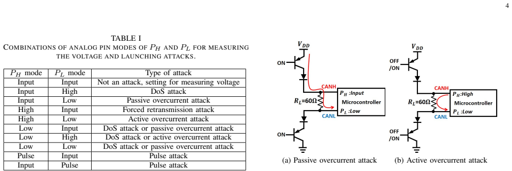
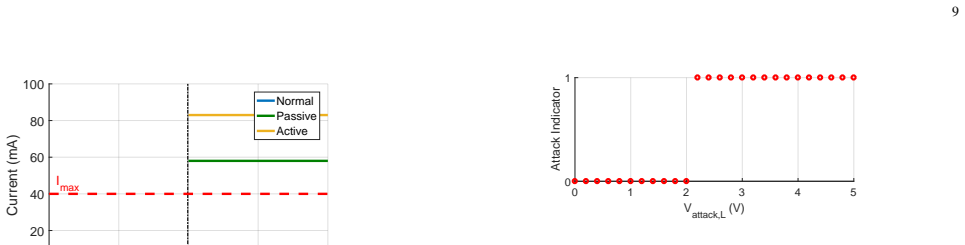
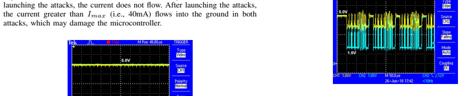
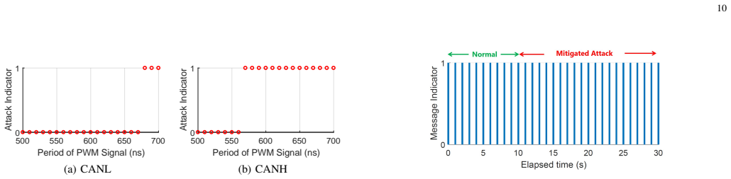
The paper's central claim is that VIDS introduces exploitable vulnerabilities via its extra wiring, enabling an adversary to damage an ECU, block messages, and force retransmissions; two hardware-based IRSs mitigate this by disconnecting the compromised ECU once attacks are detected, and the approach is evaluated on a CAN bus testbed where four voltage-based attacks are demonstrated.
What carries the argument
Hardware-based Intrusion Response Systems (IRSs) that detect voltage-based attacks from a compromised VIDS ECU and disconnect it from the CAN bus.
If this is right
- CAN bus systems using VIDS must incorporate physical disconnection capability to avoid self-induced attack surfaces.
- Security of in-vehicle networks depends on response mechanisms that act faster than the demonstrated attacks.
- Attackers can achieve denial-of-service effects on CAN by targeting the VIDS ECU specifically.
- Evaluation of IRS effectiveness requires testing against all four voltage-based attacks under operational bus loads.
Where Pith is reading between the lines
- Vehicle manufacturers may need to redesign ECU connections to minimize extra wires for any physical-property monitors.
- Standards for automotive network security could require response systems alongside detection to handle compromised monitors.
- Similar extra-connection vulnerabilities may appear in other physical-layer IDS designs for embedded networks.
- Full-vehicle deployment tests would be needed to check whether IRS timing holds under real electromagnetic interference.
Load-bearing premise
The proposed hardware IRSs detect the four voltage-based attacks in real time and disconnect the compromised ECU without introducing new vulnerabilities or false positives.
What would settle it
An experiment on the CAN testbed in which one of the four attacks completes before the IRS disconnects the ECU, or the IRS disconnects a non-attacking ECU.
Figures






read the original abstract
Data for controlling a vehicle is exchanged among Electronic Control Units (ECUs) via in-vehicle network protocols such as the Controller Area Network (CAN) protocol. Since these protocols are designed for an isolated network, the protocols do not encrypt data nor authenticate messages. Intrusion Detection Systems (IDSs) are developed to secure the CAN protocol by detecting abnormal deviations in physical properties. For instance, a voltage-based IDS (VIDS) exploits voltage characteristics of each ECU to detect an intrusion. An ECU with VIDS must be connected to the CAN bus using extra wires to measure voltages of the CAN bus lines. These extra wires, however, may introduce new attack surfaces to the CAN bus if the ECU with VIDS is compromised. We investigate new vulnerabilities of VIDS and demonstrate that an adversary may damage an ECU with VIDS, block message transmission, and force an ECU to retransmit messages. In order to defend the CAN bus against these attacks, we propose two hardware-based Intrusion Response Systems (IRSs) that disconnect the compromised ECU from the CAN bus once these attacks are detected. We develop four voltage-based attacks by exploiting vulnerabilities of VIDS and evaluate the effectiveness of the proposed IRSs using a CAN bus testbed.
Editorial analysis
A structured set of objections, weighed in public.
Referee Report
Summary. The paper investigates new vulnerabilities in voltage-based intrusion detection systems (VIDS) for Controller Area Network (CAN) buses. It demonstrates four voltage-based attacks that exploit the extra wires required by VIDS to damage an ECU, block message transmission, and force an ECU to retransmit messages. To counter these, the authors propose two hardware-based Intrusion Response Systems (IRSs) that disconnect a compromised ECU from the CAN bus upon detection of the attacks, and evaluate the attacks and IRS effectiveness on a CAN bus testbed.
Significance. If the testbed results hold, the work is significant for automotive security because it identifies attack surfaces introduced by VIDS itself and supplies concrete hardware mitigations. The experimental evaluation on a testbed, with reported attack success and IRS response times, provides empirical grounding that strengthens the central claims.
minor comments (2)
- [Abstract] Abstract: the four attacks and two IRS designs are described only at a high level; naming them or giving one-sentence characterizations would improve immediate readability.
- [Evaluation] Evaluation sections: while testbed results are reported, the manuscript would benefit from explicit discussion of voltage noise bounds or control experiments that rule out environmental artifacts in the attack demonstrations.
Simulated Author's Rebuttal
We thank the referee for the constructive and positive review, including the assessment of significance and the recommendation for minor revision. We will make the necessary minor changes in the revised manuscript.
Circularity Check
No significant circularity; experimental demonstration only
full rationale
The manuscript contains no derivations, equations, fitted parameters, or predictions that could reduce to inputs by construction. It reports concrete testbed experiments demonstrating four voltage-based attacks on VIDS and the real-time response of two proposed hardware IRS designs. All load-bearing claims rest on direct measurements and implementation details rather than self-citation chains or ansatzes; the work is therefore self-contained with no circular steps.
Axiom & Free-Parameter Ledger
axioms (1)
- domain assumption CAN protocol is designed for an isolated network without encryption or authentication
Reference graph
Works this paper leans on
-
[1]
Exploring Attack Surfaces of Voltage-Based Intrusion Detection Systems in Controller Area Networks,
S. Sagong, X. Ying, R. Poovendran, and L. Bushnell, “Exploring Attack Surfaces of Voltage-Based Intrusion Detection Systems in Controller Area Networks,” in Embedded Security in Cars Europe , 2018
work page 2018
-
[2]
ISO, “International Standard ISO 11898-1 Road Vehicles-Controller Area Network (CAN), Part 1 Data Link Layer and Physical Signaling,” 2015
work page 2015
-
[3]
——, “International Standard ISO 17987 Road Vehicles-Local Inter- connect Network (LIN), Part 1 General Information and Use Case Definition,” 2016
work page 2016
-
[4]
——, “International Standard ISO 17458 Road Vehicles-FlexRay Com- munication System, Part 1 General Information and Use Case Defini- tion,” 2013
work page 2013
-
[5]
Remote Exploitation of An Unaltered Passenger Vehicle,
C. Miller and C. Valasek, “Remote Exploitation of An Unaltered Passenger Vehicle,” in Black Hat USA , 2015
work page 2015
-
[6]
Adventures in Automotive Networks and Control Units,
——, “Adventures in Automotive Networks and Control Units,” in DEF CON21, 2013
work page 2013
-
[7]
A Survey of Remote Automotive Attack Surfaces,
——, “A Survey of Remote Automotive Attack Surfaces,” in Black Hat USA, 2014
work page 2014
-
[8]
Experimental Security Analysis of a Modern Automobile,
K. Koscher, A. Czeskis, F. Roesner, S. Patel, T. Kohno, S. Checkoway, D. McCoy, B. Kantor, D. Anderson, H. Shacham, and S. Savage, “Experimental Security Analysis of a Modern Automobile,” in IEEE Symposium on Security and Privacy , 2010, pp. 447–462
work page 2010
-
[9]
Comprehensive Experimental Analyses of Automotive Attack Surfaces,
S. Checkoway, D. McCoy, B. Kantor, D. Anderson, H. Shacham, S. Sav- age, K. Koscher, A. Czeskis, F. Roesner, and T. Kohno, “Comprehensive Experimental Analyses of Automotive Attack Surfaces,” in USENIX Conference on Security , 2011, pp. 77–92
work page 2011
-
[10]
Source Identification Using Signal Charac- teristics in Controller Area Networks,
P. S. Murvay and B. Groza, “Source Identification Using Signal Charac- teristics in Controller Area Networks,” IEEE Signal Processing Letters , vol. 21, no. 4, pp. 395–399, April 2014
work page 2014
-
[11]
Fingerprinting Electronic Control Units for Vehicle Intrusion Detection,
K.-T. Cho and K. G. Shin, “Fingerprinting Electronic Control Units for Vehicle Intrusion Detection,” in USENIX Conference on Security Symposium, 2016, pp. 911–927
work page 2016
-
[12]
Error Handling of In-vehicle Networks Makes Them Vulnera- ble,
——, “Error Handling of In-vehicle Networks Makes Them Vulnera- ble,” in ACM SIGSAC Conference on Computer and Communications Security, 2016, pp. 1044–1055
work page 2016
-
[13]
T. Hoppe, S. Kiltz, and J. Dittmann, “Security Threats to Automotive CAN Networks - Practical Examples and Selected Short-Term Counter- measures,” in International Conference on Computer Safety, Reliability, and Security , 2008, pp. 235–248
work page 2008
-
[14]
Cloak- ing the Clock: Emulating Clock Skew in Controller Area Networks,
S. Sagong, X. Ying, A. Clark, L. Bushnell, and R. Poovendran, “Cloak- ing the Clock: Emulating Clock Skew in Controller Area Networks,” in ACM/IEEE International Conference on Cyber-Physical Systems , 2018, pp. 32–42
work page 2018
-
[15]
Entropy-based Anomaly Detection for In- vehicle Networks,
M. M ¨uter and N. Asaj, “Entropy-based Anomaly Detection for In- vehicle Networks,” in IEEE Intelligent V ehicles Symposium, June 2011, pp. 1110–1115
work page 2011
-
[16]
Viden: Attacker Identification on In- Vehicle Networks,
K.-T. Cho and K. G. Shin, “Viden: Attacker Identification on In- Vehicle Networks,” in ACM SIGSAC Conference on Computer and Communications Security , 2017, pp. 1109–1123
work page 2017
-
[17]
V oltageIDS: Low-Level Communication Characteristics for Automotive Intrusion Detection System,
W. Choi, K. Joo, H. J. Jo, M. C. Park, and D. H. Lee, “V oltageIDS: Low-Level Communication Characteristics for Automotive Intrusion Detection System,” IEEE Transactions on Information F orensics and Security, vol. 13, no. 8, pp. 2114–2129, August 2018
work page 2018
-
[18]
X. Ying, S. Sagong, A. Clark, L. Bushnell, and R. Poovendran, “Shape of the cloak: Formal analysis of clock skew-based intrusion detection system in controller area networks,” IEEE Transactions on Information F orensics and Security, pp. 1–1, 2019
work page 2019
-
[19]
A Methodology for Using Intelligent Agents to Provide Automated Intrusion Response,
C. Carver, J. Hill, J. Surdu, and U. Pooch, “A Methodology for Using Intelligent Agents to Provide Automated Intrusion Response,” in IEEE Systems, Man, and Cybernetics Information Assurance and Security Workshop, 2000, pp. 110–116
work page 2000
-
[20]
Overview of 3.3V CAN (Controller Area Network) Transceiver,
Texas Instruments, “Overview of 3.3V CAN (Controller Area Network) Transceiver,” 2013
work page 2013
-
[21]
SN65HVD23x 3.3-V CAN Bus Transceivers,
——, “SN65HVD23x 3.3-V CAN Bus Transceivers,” 2015
work page 2015
-
[22]
MCP2551 CAN Transceiver Datasheet,
Microchip, “MCP2551 CAN Transceiver Datasheet,” 2016
work page 2016
- [23]
-
[24]
Introduction to the Controller Area Network (CAN),
Texas Instruments, “Introduction to the Controller Area Network (CAN),” 2016
work page 2016
-
[25]
Controller Area Network Physical Layer Requirements,
——, “Controller Area Network Physical Layer Requirements,” 2008
work page 2008
-
[26]
Arduino UNO Rev3 Technical Specification,
Arduino, “Arduino UNO Rev3 Technical Specification,” https://store. arduino.cc/usa/arduino-uno-rev3, accessed: 2018-05-07
work page 2018
- [27]
-
[28]
Am335x Sitara Processors Datasheet,
Texas Instruments, “Am335x Sitara Processors Datasheet,” 2016
work page 2016
-
[29]
ATmega 328P Automotive Datasheet,
Microchip, “ATmega 328P Automotive Datasheet,” 2015
work page 2015
- [30]
-
[31]
California Air Resource Board, “HD OBD Regulatory Documents,” 2012
work page 2012
-
[32]
Directive 98/69/EC of the European Parliament and of the Council,
The European Union, “Directive 98/69/EC of the European Parliament and of the Council,” 1998
work page 1998
-
[33]
Hyundai Global Diagnostic System,
Hyundai, “Hyundai Global Diagnostic System,” https: //hyundai.service-solutions.com/en-US/Pages/ItemDetail.aspx?SKU= GDSM-LTKITH, accessed: 2018-06-25
work page 2018
-
[34]
Ford Vehicle Communication Module,
Ford, “Ford Vehicle Communication Module,” https://www. fordtechservice.dealerconnection.com/VDIRS/wds/vcm retail renewal Latest.asp, June 2018, accessed: 2018-06-25
work page 2018
-
[35]
V olkswagen V AG-COM Diagnostic System,
Ross Tech, “V olkswagen V AG-COM Diagnostic System,” http://www. ross-tech.com/vag-com/index.html, accessed: 2018-06-25
work page 2018
-
[36]
Toyota Technical Information System,
Toyota, “Toyota Technical Information System,” https://techinfo.toyota. com/techInfoPortal, June 2018, accessed: 2018-06-25
work page 2018
-
[37]
Behavior Analysis for Safety and Security in Automotive Systems,
R. Rieke, M. Seidemann, E. K. Talla, D. Zelle, and B. Seeger, “Behavior Analysis for Safety and Security in Automotive Systems,” in Euromicro International Conference on Parallel, Distributed and Network-based Processing, March 2017, pp. 381–385
work page 2017
- [38]
- [39]
-
[40]
MCP2515 Stand-Alone CAN Controller with SPI Inter- face,
Microchip, “MCP2515 Stand-Alone CAN Controller with SPI Inter- face,” 2016
work page 2016
-
[41]
Radial Lead Fuses 272/273/274/278/279 Series Very Fast- Acting Fuses Datasheet,
LittelFuse, “Radial Lead Fuses 272/273/274/278/279 Series Very Fast- Acting Fuses Datasheet,” 2018
work page 2018
-
[42]
Fuse Characteristics, Terms and Condition Factors,
——, “Fuse Characteristics, Terms and Condition Factors,” 2014
work page 2014
-
[43]
Fuse- Tethers in MEMS: Theory and Operation,
Y .-S. Chiu, K.-S. Chang, R. Johnstone, and M. Parameswaran, “Fuse- Tethers in MEMS: Theory and Operation,” in Canadian Conference on Electrical and Computer Engineering , May 2005, pp. 1517–1520
work page 2005
-
[44]
A Controllable IC-compatible Thin- Film Fuse Realized using Electro-Explosion,
X. Dinga, W. Loub, and Y . Feng, “A Controllable IC-compatible Thin- Film Fuse Realized using Electro-Explosion,” AIP Advances , vol. 6, 2016
work page 2016
-
[45]
“LittelFuse Fuses vs. PTCs,” https://www.littelfuse.com/about-us/ education-center/fuses-vs-ptcs.aspx/, accessed: 2019-01-31
work page 2019
discussion (0)
Sign in with ORCID, Apple, or X to comment. Anyone can read and Pith papers without signing in.