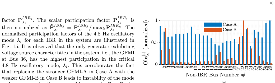
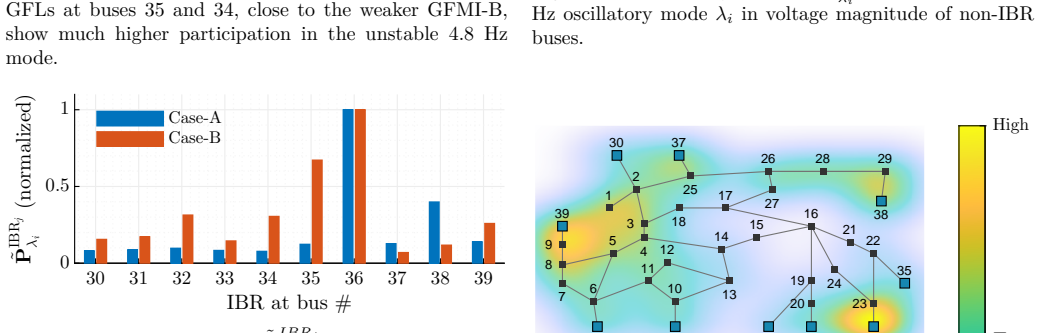
Frequency-Domain Compliance Assessment of Grid-Forming Devices
Pith reviewed 2026-05-09 16:46 UTC · model grok-4.3
The pith
Frequency-domain Bode plot minima provide an equivalent compliance test for grid-forming inverters acting as voltage sources behind impedance.
A machine-rendered reading of the paper's core claim, the machinery that carries it, and where it could break.
Core claim
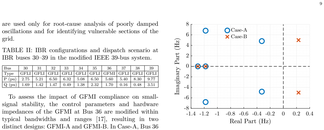
The voltage-source-behind-impedance characteristic of grid-forming inverters can be verified by requiring the frequency-domain Jacobian elements P(s)/θ(s) and Q(s)/V(s) to remain above specified minimum magnitudes in their Bode plots across the sub-transient frequency range. This frequency-domain rule is shown to be equivalent to the conventional time-domain criterion that evaluates power or current responses to step changes in terminal voltage phase and magnitude. The method is implemented on generic grid-forming inverter models in electromagnetic transient simulation and is used to illustrate how compliance status influences small-signal stability margins in the IEEE 39-bus bulk-power test
What carries the argument
The minimum expected Bode plot magnitudes of the frequency-domain Jacobian elements P(s)/θ(s) and Q(s)/V(s) across the chosen frequency band, which enforce the required stiffness response.
If this is right
- Compliance assessment can be performed with frequency-response data that avoids the measurement challenges of sub-cycle transients.
- System operators obtain a concrete specification for the expected stiffness behavior that can be checked in simulation or hardware.
- The proven equivalence permits existing time-domain standards to be translated directly into frequency-domain requirements.
- Small-signal stability studies of large grids can account for individual inverter compliance status without additional time-domain simulations.
- Model validation in tools such as PSCAD can incorporate the frequency-domain checks as a standard pass-fail gate.
Where Pith is reading between the lines
- The frequency-domain formulation may combine naturally with other small-signal analysis methods already expressed in the same domain.
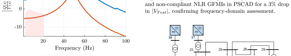
- The exact frequency band and minimum levels could be tuned to local grid strength or specific operating points.
- Phasor-based monitoring equipment might estimate the same transfer functions in real time to track ongoing compliance.
Load-bearing premise
The chosen frequency range and Bode plot minima in the Jacobian elements are assumed to fully and equivalently represent the voltage-source-behind-impedance behavior for practical grid-forming inverters under all relevant conditions.
What would settle it
A grid-forming inverter that passes the time-domain step-response compliance test but violates one or more of the proposed minimum Bode plot levels (or the reverse) would show the two criteria are not equivalent.
Figures


read the original abstract
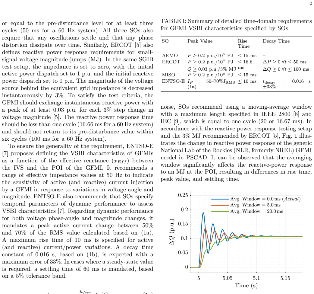
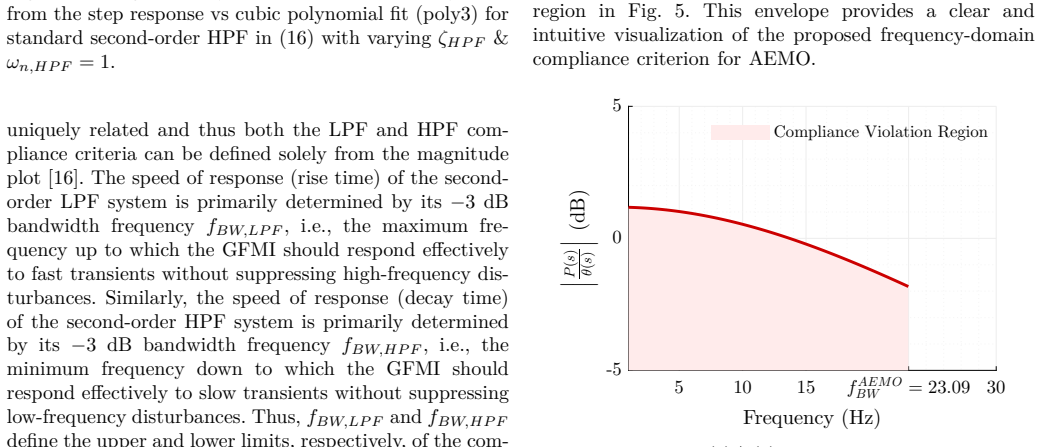
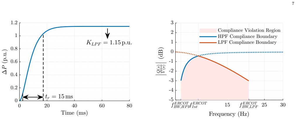
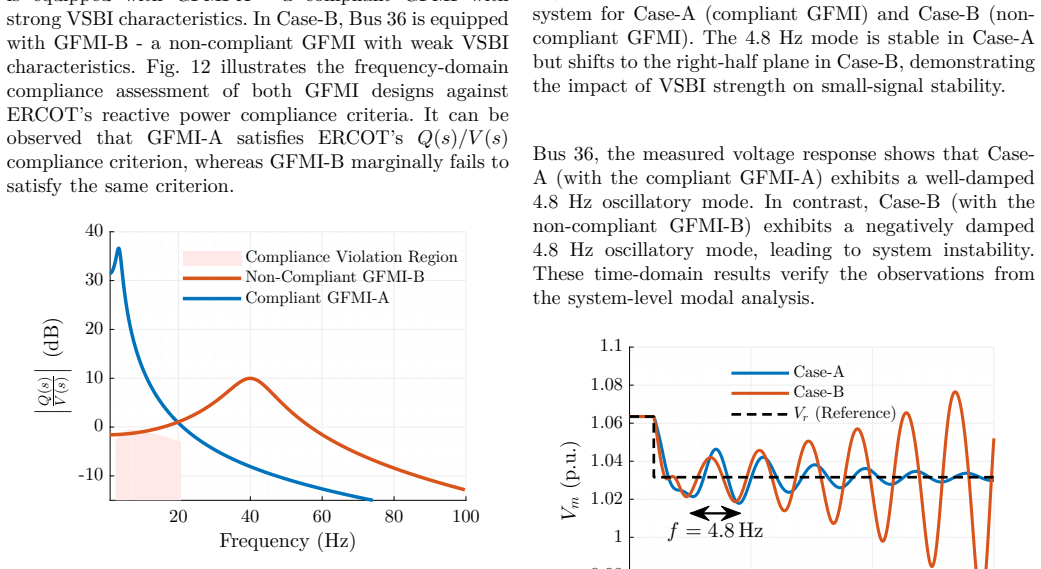
Grid-ForMing Inverters (GFMIs) are expected to provide voltage stiffness to the grid. Explicitly, system operators (SOs) and regulators expect GFMIs to behave like a "voltage source behind impedance (VSBI)" in the (sub)-transient time frame. SOs assess this VSBI characteristic of GFMIs during compliance by defining a pass-fail time-domain criterion. This is done by evaluating the GFMIs' active (or reactive) power/current response to step changes in voltage phase (and magnitude) at its terminals. However, this approach is prone to errors due to poorly defined measurement specifications for very fast (less than a cycle) transients. To address this, this work proposes a compliance criterion for the VSBI characteristic of GFMIs in the frequency domain based on elements of the frequency-domain Jacobian. The compliance criterion is defined in terms of the minimum expected P(s)/\theta(s) and Q(s)/V(s) Bode plot characteristics across a specific frequency range. The equivalence between the time-domain and frequency-domain criteria is established. The proposed method is demonstrated by assessing the compliance of generic NLR (formerly NREL) GFMI models in PSCAD. Furthermore, the impact of GFMI compliance on the small-signal stability of the IEEE 39-bus bulk-power system is demonstrated.
Editorial analysis
A structured set of objections, weighed in public.
Referee Report
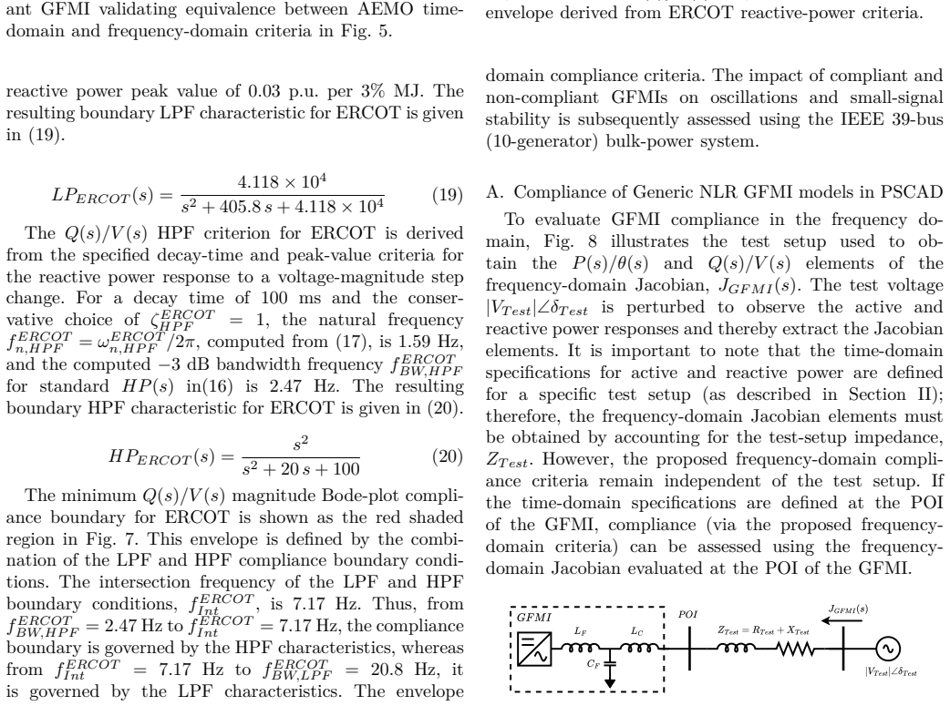
Summary. The manuscript proposes a frequency-domain compliance criterion for the voltage source behind impedance (VSBI) characteristic of Grid-Forming Inverters (GFMIs), defined via the minimum gains of the P(s)/θ(s) and Q(s)/V(s) elements of the frequency-domain Jacobian over a chosen frequency band. It claims this criterion is equivalent to the conventional time-domain pass/fail test based on active/reactive power or current responses to terminal voltage phase and magnitude steps. The equivalence is established analytically, the method is demonstrated on generic NLR GFMI models in PSCAD, and the effect of compliance on small-signal stability is illustrated for the IEEE 39-bus system.
Significance. If the claimed equivalence is shown to hold under realistic operating conditions, the frequency-domain formulation would provide a practical alternative to time-domain compliance testing that avoids the documented difficulties of sub-cycle transient measurements. The linkage to small-signal stability of a standard test system further indicates potential utility for system operators. The use of publicly referenced generic models supports reproducibility.
major comments (2)
- [§4] §4 (Equivalence derivation): The equivalence between the time-domain step-response criterion and the Bode-plot minima is derived under small-signal linearization of the Jacobian. However, practical GFMIs incorporate nonlinear elements (current limiting, saturation, PLL dynamics, virtual-impedance switching) that a step change can excite; the manuscript does not demonstrate that the linear Bode thresholds remain predictive when these nonlinearities are active, which directly affects the central claim that the frequency-domain criterion fully captures VSBI compliance in the sub-transient regime.
- [§5] §5 (PSCAD demonstration): The compliance assessment is performed on generic NLR models, yet no quantitative comparison is provided between the frequency-domain predictions and the actual nonlinear time-domain step responses under conditions that trigger current limiting or saturation. Without such a side-by-side error analysis or falsification test, it remains unclear whether the proposed minima thresholds correctly classify compliance when the linear assumption is violated.
minor comments (2)
- [Abstract] The abstract states that equivalence is established but supplies no explicit frequency range or threshold values; including these numerical details would improve immediate readability.
- [§5] Figure captions in the PSCAD results section could explicitly state the operating point and whether current limiting was engaged during the depicted transients.
Simulated Author's Rebuttal
We thank the referee for the detailed and constructive review of our manuscript. The comments raise important points about the scope of the linear equivalence and the need for validation under nonlinear conditions. We address each major comment below and outline the revisions we will make.
read point-by-point responses
-
Referee: [§4] §4 (Equivalence derivation): The equivalence between the time-domain step-response criterion and the Bode-plot minima is derived under small-signal linearization of the Jacobian. However, practical GFMIs incorporate nonlinear elements (current limiting, saturation, PLL dynamics, virtual-impedance switching) that a step change can excite; the manuscript does not demonstrate that the linear Bode thresholds remain predictive when these nonlinearities are active, which directly affects the central claim that the frequency-domain criterion fully captures VSBI compliance in the sub-transient regime.
Authors: The analytical derivation in §4 is performed under the small-signal linearization of the Jacobian, as is standard for frequency-domain analysis of this type. Conventional time-domain compliance tests likewise rely on small step perturbations precisely to remain within the linear operating region and avoid exciting nonlinearities such as current limiting or saturation. The proposed frequency-domain criterion is therefore intended as an equivalent assessment tool for the same linear VSBI characteristic that the time-domain tests target. We acknowledge that the manuscript does not provide explicit verification of the Bode minima when nonlinear elements become active. In the revised manuscript we will add a new subsection in §4 that explicitly states the small-signal scope of the equivalence, clarifies that the criterion does not replace time-domain testing for large-signal events, and discusses the conditions under which the linear thresholds are expected to remain predictive. revision: yes
-
Referee: [§5] §5 (PSCAD demonstration): The compliance assessment is performed on generic NLR models, yet no quantitative comparison is provided between the frequency-domain predictions and the actual nonlinear time-domain step responses under conditions that trigger current limiting or saturation. Without such a side-by-side error analysis or falsification test, it remains unclear whether the proposed minima thresholds correctly classify compliance when the linear assumption is violated.
Authors: The demonstrations in §5 employ the publicly available generic NLR GFMI models with step changes sized to keep the responses within the linear regime, consistent with the analytical equivalence derived earlier. No side-by-side quantitative comparison under current-limiting or saturation conditions was included, because the section focuses on validating the frequency-domain formulation against the linear time-domain criterion. We agree that such a comparison would strengthen the presentation. In the revised manuscript we will add new PSCAD results that activate current limiting, present the corresponding time-domain responses, and tabulate the classification outcomes (pass/fail) from both the frequency-domain minima and the nonlinear time-domain tests, including any observed discrepancies. revision: yes
Circularity Check
No circularity: frequency-domain criterion derived independently via linear systems equivalence
full rationale
The paper defines the time-domain VSBI compliance criterion from explicit step-response measurements and then derives the frequency-domain version directly from the small-signal Jacobian transfer functions P(s)/θ(s) and Q(s)/V(s). Equivalence is shown by standard Fourier/Laplace relationships between step inputs and Bode characteristics under linearised assumptions, without any fitted parameters, self-referential definitions, or load-bearing self-citations. The central claim therefore rests on independent mathematical structure rather than reducing to its own inputs by construction.
Axiom & Free-Parameter Ledger
free parameters (1)
- specific frequency range
axioms (2)
- domain assumption Small-signal linearization applies to the sub-transient transients of interest.
- domain assumption GFMIs are expected to exhibit VSBI behavior in the sub-transient time frame.
Reference graph
Works this paper leans on
-
[1]
Equivalent Circuit Modeling of Grid-Forming Inverters in (Sub)-Transient Time-Frame
A. Gupta, B. Chaudhuri, and M. O’Malley, “Equivalent circuit modeling of grid-forming inverters in (sub)-transient time- frame,” arXiv preprint arXiv:2602.12202, 2026
work page internal anchor Pith review Pith/arXiv arXiv 2026
-
[2]
National Grid Electricity System Operator (ESO), “ Workgroup consultation GC0137: Minimum specification required for provi- sion of GB grid forming (GBGF) capability ,” ESO, Tech. Rep., Mar. 2021
work page 2021
-
[3]
Specific study requirements for grid energy stor- age systems, version 1.0 ,
Fingrid Oyj, “ Specific study requirements for grid energy stor- age systems, version 1.0 ,” Fingrid Oyj, Tech. Rep., Jun. 2023
work page 2023
-
[4]
Voluntary spec- ification for grid-forming inverters ,
Australian Energy Market Operator (AEMO), “ Voluntary spec- ification for grid-forming inverters ,” AEMO, Tech. Rep., May 2023
work page 2023
-
[5]
Electric Reliability Council of Texas (ERCOT), “ Advanced Grid Support Energy Storage Resource (AGS-ESR) Functional Specification and Test Requirements for the ERCOT Grid, Version 1.0,” Sep. 2024
work page 2024
-
[6]
Midcontinent Independent System Operator (MISO), “ Grid- forming battery energy storage capabilities, performance, and simulation test requirements proposal ,” MISO, Tech. Rep., Jul. 2024
work page 2024
-
[7]
Grid forming capability of power park modules: First interim report on technical requirements ,
European Network of Transmission System Operators for Elec- tricity, “ Grid forming capability of power park modules: First interim report on technical requirements ,” ENTSO-E, Tech. Rep., May 2024
work page 2024
-
[8]
IEEE Power and Energy Society, IEEE Standard for Intercon- nection and Interoperability of Inverter-Based Resources (IBRs) Interconnecting with Associated Transmission Electric Power Systems, IEEE Std. IEEE Std 2800-2022, Apr. 2022
work page 2022
-
[9]
IEC 61 400-21-1:2019, May 2019, international Standard
Wind energy generation systems – Part 21-1: Measurement and assessment of electrical characteristics , International Elec- trotechnical Commission Std. IEC 61 400-21-1:2019, May 2019, international Standard
work page 2019
-
[10]
Testing the Per- formance of Grid-Forming Resources ,
Energy Systems Integration Group (ESIG), “ Testing the Per- formance of Grid-Forming Resources ,” ESIG, Tech. Rep., Sep. 2025
work page 2025
-
[11]
A testing framework for grid-forming resources,
S. Shah, W. Yan, P. Koralewicz, V. Gevorgian, D. Ramasubra- manian, R. Wallen, A. Hoke, B. Kroposki, and B. Mather, “A testing framework for grid-forming resources,” in 2023 IEEE Power & Energy Society General Meeting (PESGM), 2023, pp. 1–5
work page 2023
-
[12]
Methodology for analysing the essential voltage source characteristics of power systems components,
E. A vdiaj, F. J. Cifuentes Garcia, and J. Beerten, “Methodology for analysing the essential voltage source characteristics of power systems components,” TechRxiv Preprint, Jan. 2025
work page 2025
-
[13]
R. W. Kenyon, A. Sajadi, A. Hoke, and B.-M. Hodge, “Open- source PSCAD grid-following and grid-forming inverters and a benchmark for zero-inertia power system simulations,” in Proc. IEEE Kansas Power and Energy Conf. (KPEC), Apr. 2021, pp. 1–6
work page 2021
-
[14]
Electric Power Research Institute (EPRI), “ An overview of grid- forming inverter technologies and the readiness of power systems worldwide to deploy the technology ,” EPRI, Tech. Rep., Dec. 2024
work page 2024
-
[15]
N. S. Nise, Control Systems Engineering, 7th ed. Hoboken, NJ: John Wiley & Sons, 2015
work page 2015
-
[16]
A. V. Oppenheim and R. W. Schafer, Discrete-Time Signal Processing, 3rd ed. Upper Saddle River, NJ, USA: Prentice Hall, 2009
work page 2009
-
[17]
UNIFI’s Grid-Forming (GFM) Inverter Reference Design ,
D. Chatterjee, J. Triemstra, C. Macías, W. Cai, K. Tatkare, R. Mallik, and B. Johnson, “ UNIFI’s Grid-Forming (GFM) Inverter Reference Design ,” The University of Texas at Austin, Technical Report NREL/TP-5D00-92994, July 2025
work page 2025
-
[18]
Benchmark Systems for Small-Signal Stability Analysis and Control ,
IEEE PES Task Force on Benchmark Systems for Stability Con- trols, “ Benchmark Systems for Small-Signal Stability Analysis and Control ,” IEEE Power & Energy Society, Tech. Rep. PES- TR18, Aug. 2015
work page 2015
-
[19]
Diagnosis and Mitigation of Observed Oscillations in IBR-Dominant Power Systems: A Practical Guide ,
Energy Systems Integration Group (ESIG), “ Diagnosis and Mitigation of Observed Oscillations in IBR-Dominant Power Systems: A Practical Guide ,” ESIG, Technical Report, Aug. 2024
work page 2024
-
[20]
EMT— RMS modeling trade-off for IBR-driven sub-synchronous oscil- lations,
M. S. Javaid, B. Chaudhuri, F. Teng, and Z. Akhtar, “EMT— RMS modeling trade-off for IBR-driven sub-synchronous oscil- lations,” IEEE Transactions on Power Systems, 2025
work page 2025
discussion (0)
Sign in with ORCID, Apple, or X to comment. Anyone can read and Pith papers without signing in.