REVIEW 3 major objections 6 minor 40 references
GelBelt: A Vision-based Tactile Sensor for Continuous Sensing of Large Surfaces
T0 review · 3 major / 6 minor · reviewed 2026-08-10 · deepseek-v4-flash
Pith's one-line read An elastomeric belt on two wheels lets a camera-based tactile sensor scan large surfaces continuously, stitching normal maps into a 3D mesh with average alignment above 0.97.
desk verdict Solid new hardware for continuous tactile scanning; the stitching claim needs external odometry validation and error bars, but the design and experiments justify a serious look. read the letter →
The pith
A machine-rendered reading of the paper's core claim, the machinery that carries it, and where it could break.
The reading
What carries the argument
The load-bearing design is the belt-and-two-wheels geometry with an optical sensing window between the wheels: the belt's outer surface carries reflective coating for photometric stereo, while the inner surface slides over a clear acrylic plate through a low-friction transparent tape layer. Side markers with variable spacing act as a visual encoder; their displacement between frames initializes optical flow, which registers successive surface-normal maps into one global map. The same markers feed trained MLPs that estimate contact roll/pitch and normal force.
What would settle it
Scan a flat calibration plate with a known grid while tracking the sensor's true pose with an external motion-capture system, and compare marker-derived displacement with the true translation: if the belt slips under load, the reconstructed grid will shear or drift even though the true motion is a pure translation. The paper's own restriction to relatively flat surfaces and planar motion (Section IV-B) means that rolling over a curved or tilted surface and checking whether the global normal map preserves the known surface angles is a direct test of the claimed scope.
Extended reading notes
Core claim
GelBelt's central claim is that decoupling the elastomer from a rigid support plate by making the elastomer a belt that rolls over two wheels removes the main obstacle to continuous vision-based tactile scanning. Each frame still uses photometric stereo to recover a local normal map, but the belt's large flat sensing region (60 mm by 40 mm) avoids the narrow, depth-varying contact zone that limits cylindrical roller sensors. Frame-to-frame motion is measured from printed markers on the belt edges, which seed an optical-flow registration of the normal maps; the registered maps are averaged and Poisson-integrated into a global height map. The reported result is an average dot product above 0.97 between estimated and reference surface normals for scanning speeds up to 45 mm/s, with reconstruction of sub-millimeter defects comparable to a commercial high-resolution tactile sensor, and with contact force estimated within about 1 N (95% confidence) up to 60 N.
Load-bearing premise
The whole stitching pipeline rests on the assumption that the belt rolls without slip over both wheels and the target surface, so the measured marker displacement exactly equals the sensor's translation, and that the scanned surface is relatively flat with planar motion.
Editorial extensions
If this is right
- Large, relatively flat surfaces can be scanned continuously at speeds up to 45 mm/s while keeping average normal-vector alignment above 0.97, which the authors identify as the fastest accurate vision-based tactile scanning system.
- Sub-millimeter defects on aircraft parts are reconstructed well enough to be compared against a commercial high-resolution tactile sensor, supporting use in industrial quality control and maintenance.
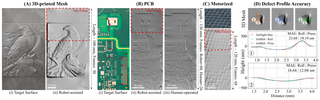
- Both robot-assisted and manual scanning produce low planar drift on a PCB surface (mean distance error below 0.4 mm and angle error below 0.4 degrees), so the sensor tolerates less controlled motion.
- Because markers also estimate contact force within about 1 N and contact angles within a few tenths of a degree, the same hardware can support closed-loop control of scanning pressure in future work.
- A motorized self-driven version demonstrates standalone scanning, although the authors report its reconstruction accuracy still needs refinement.
Reading between the lines
- The same belt geometry could be scaled to wider or longer sensing patches, since the optical window is defined by the wheel spacing and belt width rather than by a rigid support plate.
- Combining the marker-based encoder with external pose tracking, as the paper notes would be needed for complicated 3D shapes, could extend GelBelt to curved surfaces without changing the core stitching method.
- The reported speed-accuracy trade-off suggests an adaptive scanning policy: move quickly over smooth regions and slow down when the marker-based force or angle signal indicates a suspected defect.
- A continuous printed or molded marker pattern could replace the discrete laser-engraved dots, potentially making the encoder more robust on non-textured surfaces and under faster motion.
Signed reviews
Editorial analysis
A structured set of objections, weighed in public.
Referee Report
Summary. GelBelt is a vision-based tactile sensor built around an elastomeric belt stretched over two wheels, with a rigid optical assembly between them. The key idea is to decouple the elastomer from a rigid support so that the belt can roll continuously over a large, comparatively flat surface while a 40 mm by 60 mm sensing region is imaged at each frame. The authors calibrate surface-normal prediction with an MLP from RGBXY to surface gradients using a known spherical indenter, stitch overlapping normal maps via optical flow seeded by side-marker displacements, and reconstruct height maps by Poisson integration. They report average normal-vector dot products above 0.97 for single-frame and global reconstruction, accuracy comparisons against GelSight Max on aircraft-part defects, marker-based normal-force and contact-angle estimation, and robot, manual, and motorized scanning demonstrations. The claimed contribution is a continuous-scanning sensor that achieves accurate reconstruction at speeds up to 45 mm/s, which the authors state is the fastest accurate VBTS scanning system known to them.
Significance. If the accuracy claims hold, GelBelt addresses a real gap in vision-based tactile sensing: existing cylindrical rollers have narrow, depth-varying contact regions and are difficult to move quickly, whereas GelBelt provides a large uniform sensing area and a simple rolling mechanism. The paper includes useful engineering contributions: physics-based optical design in Blender, a two-layer silicone belt, marker-based odometry, and independent force and angle calibration with an F/T sensor. The comparison with GelSight Max provides external validation of defect reconstruction. However, the headline accuracy is reported without error bars, and the marker-based frame-to-frame motion estimate is not validated against external ground truth, so the significance is conditional on additional experimentation.
major comments (3)
- [Section IV-B and Section V] The same marker-displacement field serves both as the initial frame-to-frame translation for optical flow stitching (Section IV-B) and as the feature for contact-normal-force and surface-angle estimation (Section V). Because the belt is a soft elastomer, the marker motion inevitably contains rigid rolling translation, elastic stretch, and force-induced shear deformation. The manuscript neither separates these components nor validates the marker-derived translation against an external motion ground truth (for example, the robot end-effector pose). The global reconstruction experiments in Section VI-B do not report or control the contact normal force during the scans, so a force-induced bias in the marker-based initial displacement could propagate through optical flow and bias the stitched normal map. The >0.97 dot-product claim therefore lacks evidence in the coupled sensing regime in which the marker field is used for both odometry and force sensing.
- [Figure 5C and Section VI-B] The central quantitative claim that the average dot product remains above 0.97 at speeds up to 45 mm/s is presented without error bars, confidence intervals, or the number of repeated trials. The single-frame accuracy map in Figure 5A shows clear spatial variability and low-accuracy regions near the green and blue lights, but no aggregate statistics for the full sensing area are given. At minimum, the authors should report the mean and standard deviation over repeated scans and the number of trials per speed, since the margin between the claimed 0.97 threshold and the observed local minima is not quantified.
- [Section VI-B, drift evaluation] The global reconstruction drift is evaluated only on a textured PCB with control points (Figure 6B), giving mean absolute errors of 0.333 mm in robot-assisted mode and 0.381 mm in manual mode. The paper explicitly states in Section IV-B that for non-textured or repeating-texture surfaces, the side markers are the only registration signal. The drift experiment does not include such a surface, nor does it vary contact force, so it does not validate marker-only odometry in the regime where the sensing modality is most dependent on the unvalidated kinematic coupling. A non-textured surface reconstruction with marker-only registration and an independent position check would directly test the central claim.
minor comments (6)
- [Section VI-A] There is a typo in the first paragraph of the single-frame reconstruction experiment: 'GelBet' should be 'GelBelt'.
- [Section III-B] The word 'consequently' appears lowercase at the beginning of a sentence; it should be capitalized as 'Consequently'.
- [Section VI-A] The description of dot-product values says '-1 to 1 corresponding to the fully-aligned and opposite-direction vectors, respectively'; for unit normal vectors, 1 corresponds to aligned and -1 to opposite, so the order should be reversed.
- [Figure 5D] The text refers to 'Fig. 5 D2-1' but the figure layout and labels are not explained; please clarify which subplot shows the smoothed sharp-edge defect.
- [Section VI] The sampling-rate statement ('capped the sampling rate, ~6 to 10 Hz') is vague; a specific value or a clear explanation of the cap would improve reproducibility.
- [Section VI-B] The claim that GelBelt is the fastest accurate VBTS scanning system relies only on comparison with TouchRoller's 11 mm/s; a brief table of reported speeds of other cylindrical sensors would make the claim more transparent.
Circularity Check
No significant circularity: the reconstruction, force, and angle claims are validated against external ground truth rather than derived from their own inputs.
full rationale
The paper's central reconstruction claim is not circular. The per-pixel normal estimator is trained on an 8 mm ball indented at 143 locations, with ground-truth normals computed from the known ball geometry, and accuracy is then evaluated on a hexagonal pyramid indenter with known dimensions in Section VI-A, a different geometry from the calibration target. The global stitching accuracy is evaluated against the same hex geometry after rolling and against control-point distances measured on a PCB with a caliper in Section VI-B, so the stitched map is compared with externally measured geometry. The force and angle models are trained with ground truth from a 6-axis F/T sensor on the robot wrist in Section V, which is independent of the marker-derived features. The speed comparison uses the external TouchRoller value of 11 mm/s from reference [20]. The only self-citations, references [32], [4], [36], and [38], are used for design simulation, related defect-inspection context, and prior tactile-sensor design; none is invoked as the sole justification for the paper's accuracy or speed claims. The explicitly stated flat-surface limitation in Section IV-B narrows the claim but does not create circularity. The main weakness is the unvalidated no-slip kinematic coupling between belt, wheels, and surface in Section IV-B, but that is a correctness or robustness risk, not a circular reduction: the marker displacement is not fitted to the reconstruction target, and the reconstruction accuracy is not defined in terms of the marker displacement. No equation or fitted parameter is equivalent to the claimed output by construction.
Assumptions & free parameters
free parameters (3)
- MLP weights for gradient prediction (RGBXY to gx, gy) =
trained weights, 3-layer MLP 128-32-32
- MLP weights for force and angle estimation =
trained weights, 512-256-128
- Spline feature points (10 per side) =
20 y-values at fixed x-axis values
assumptions (4)
- domain assumption Photometric stereo assumptions: diffuse reflective coating, fixed calibrated lighting, linear camera response
- domain assumption No-slip rolling between belt, wheels, and surface
- domain assumption Surface is relatively flat and motion is planar translation
- standard math Poisson integration of normal maps yields a valid height map
Cite this review
Pith. "Pith review of GelBelt: A Vision-based Tactile Sensor for Continuous Sensing of Large Surfaces." pith.science (2026). https://pith.science/paper/PQOO4VL5
@misc{pith2026250106263,
  author       = {Pith},
  title        = {Pith review of: GelBelt: A Vision-based Tactile Sensor for Continuous Sensing of Large Surfaces},
  year         = {2026},
  howpublished = {\url{https://pith.science/paper/PQOO4VL5}},
  note         = {Machine review of arXiv:2501.06263}
}
read the original abstract
Scanning large-scale surfaces is widely demanded in surface reconstruction applications and detecting defects in industries' quality control and maintenance stages. Traditional vision-based tactile sensors have shown promising performance in high-resolution shape reconstruction while suffering limitations such as small sensing areas or susceptibility to damage when slid across surfaces, making them unsuitable for continuous sensing on large surfaces. To address these shortcomings, we introduce a novel vision-based tactile sensor designed for continuous surface sensing applications. Our design uses an elastomeric belt and two wheels to continuously scan the target surface. The proposed sensor showed promising results in both shape reconstruction and surface fusion, indicating its applicability. The dot product of the estimated and reference surface normal map is reported over the sensing area and for different scanning speeds. Results indicate that the proposed sensor can rapidly scan large-scale surfaces with high accuracy at speeds up to 45 mm/s.
Figures


Figures from the paper (4 more)



Reference graph
Works this paper leans on
-
[1]
Optimization of the recognition of defects in flat steel products with the cost matrices theory,
F. Dupont, C. Odet, and M. Cartont, “Optimization of the recognition of defects in flat steel products with the cost matrices theory,” NDT & E International , vol. 30, no. 1, pp. 3–10, 1997
work page 1997
-
[2]
Recent advances in surface defect inspection of industrial products using deep learning techniques,
X. Zheng, S. Zheng, Y . Kong, and J. Chen, “Recent advances in surface defect inspection of industrial products using deep learning techniques,” The International Journal of Advanced Manufacturing Technology, vol. 113, pp. 35–58, 2021
work page 2021
-
[3]
A smart surface inspection system using faster r-cnn in cloud-edge computing environ- ment,
Y . Wang, M. Liu, P. Zheng, H. Yang, and J. Zou, “A smart surface inspection system using faster r-cnn in cloud-edge computing environ- ment,” Advanced Engineering Informatics , vol. 43, p. 101037, 2020
work page 2020
-
[4]
Robotic defect in- spection with visual and tactile perception for large-scale components,
A. Agarwal, A. Ajith, C. Wen, V . Stryzheus, B. Miller, M. Chen, M. K. Johnson, J. L. S. Rincon, J. Rosca, and W. Yuan, “Robotic defect in- spection with visual and tactile perception for large-scale components,” in 2023 IEEE/RSJ International Conference on Intelligent Robots and Systems (IROS). IEEE, 2023, pp. 10 110–10 116
work page 2023
-
[5]
J. N. Dastgerdi, O. Jaberi, and H. Remes, “Influence of internal and surface defects on the fatigue performance of additively manufactured stainless steel 316l,” International Journal of Fatigue , vol. 163, p. 107025, 2022
work page 2022
-
[6]
Surface metrology using an elas- tomeric sensor,
M. K. Johnson and E. H. Adelson, “Surface metrology using an elas- tomeric sensor,” in Applied Industrial Optics: Spectroscopy, Imaging and Metrology. Optica Publishing Group, 2011, p. AITuB4
work page 2011
-
[7]
Gelsight: High-resolution robot tactile sensors for estimating geometry and force,
W. Yuan, S. Dong, and E. H. Adelson, “Gelsight: High-resolution robot tactile sensors for estimating geometry and force,” Sensors, vol. 17, no. 12, p. 2762, 2017
2017
-
[8]
More than a feeling: Learning to grasp and regrasp using vision and touch,
R. Calandra, A. Owens, D. Jayaraman, J. Lin, W. Yuan, J. Malik, E. H. Adelson, and S. Levine, “More than a feeling: Learning to grasp and regrasp using vision and touch,” IEEE Robotics and Automation Letters, vol. 3, no. 4, pp. 3300–3307, 2018
2018
Show all 40 references
-
[9]
Measurement of shear and slip with a gelsight tactile sensor,
W. Yuan, R. Li, M. A. Srinivasan, and E. H. Adelson, “Measurement of shear and slip with a gelsight tactile sensor,” in 2015 IEEE International Conference on Robotics and Automation (ICRA). IEEE, 2015, pp. 304–311
2015
-
[10]
Localization and manipulation of small parts using gelsight tactile sensing,
R. Li, R. Platt, W. Yuan, A. Ten Pas, N. Roscup, M. A. Srinivasan, and E. Adelson, “Localization and manipulation of small parts using gelsight tactile sensing,” in 2014 IEEE/RSJ International Conference on Intelligent Robots and Systems . IEEE, 2014, pp. 3988–3993
2014
-
[11]
Microgeometry capture using an elastomeric sensor,
M. K. Johnson, F. Cole, A. Raj, and E. H. Adelson, “Microgeometry capture using an elastomeric sensor,” ACM Transactions on Graphics (TOG), vol. 30, no. 4, pp. 1–8, 2011
2011
-
[12]
Improved gelsight tactile sen- sor for measuring geometry and slip,
S. Dong, W. Yuan, and E. H. Adelson, “Improved gelsight tactile sen- sor for measuring geometry and slip,” in 2017 IEEE/RSJ International Conference on Intelligent Robots and Systems (IROS) , 2017, pp. 137– 144
2017
-
[13]
Gelslim 3.0: High-resolution measurement of shape, force and slip in a compact tactile-sensing finger,
I. H. Taylor, S. Dong, and A. Rodriguez, “Gelslim 3.0: High-resolution measurement of shape, force and slip in a compact tactile-sensing finger,” in 2022 International Conference on Robotics and Automation (ICRA). Philadelphia, PA, USA: IEEE, 2022, pp. 10 781–10 787
2022
-
[14]
Gelsight fin ray: Incorporating tactile sensing into a soft compliant robotic gripper,
S. Q. Liu and E. H. Adelson, “Gelsight fin ray: Incorporating tactile sensing into a soft compliant robotic gripper,” in 2022 IEEE 5th International Conference on Soft Robotics (RoboSoft) . Edinburgh, United Kingdom: IEEE, 2022, pp. 925–931
2022
-
[15]
Soft, round, high resolution tactile fingertip sensors for dexterous robotic manipulation,
B. Romero, F. Veiga, and E. Adelson, “Soft, round, high resolution tactile fingertip sensors for dexterous robotic manipulation,” in 2020 IEEE International Conference on Robotics and Automation (ICRA) . Paris, France: IEEE, 2020, pp. 4796–4802
2020
-
[16]
Gelsight360: An omnidirectional camera-based tactile sensor for dexterous robotic manipulation,
M. H. Tippur and E. H. Adelson, “Gelsight360: An omnidirectional camera-based tactile sensor for dexterous robotic manipulation,” arXiv preprint arXiv:2304.04268, 2023
2023 arXiv
-
[17]
Rainbowsight: A family of generalizable, curved, camera-based tactile sensors for shape reconstruction,
——, “Rainbowsight: A family of generalizable, curved, camera-based tactile sensors for shape reconstruction,” in 2024 IEEE International Conference on Robotics and Automation (ICRA) . IEEE, 2024, pp. 1114–1120
2024
-
[18]
Gelsight svelte: A human finger-shaped single-camera tactile robot finger with large sensing coverage and proprioceptive sensing,
J. Zhao and E. H. Adelson, “Gelsight svelte: A human finger-shaped single-camera tactile robot finger with large sensing coverage and proprioceptive sensing,” in 2023 IEEE/RSJ International Conference on Intelligent Robots and Systems (IROS) . IEEE, 2023, pp. 8979– 8984
2023
-
[19]
Detection of foreign bodies in soft foods employing tactile image sensor,
K. Shimonomura, T. Chang, and T. Murata, “Detection of foreign bodies in soft foods employing tactile image sensor,” Frontiers in Robotics and AI , vol. 8, p. 774080, 2021
2021
-
[20]
Touchroller: A rolling optical tactile sensor for rapid assessment of textures for large surface areas,
G. Cao, J. Jiang, C. Lu, D. F. Gomes, and S. Luo, “Touchroller: A rolling optical tactile sensor for rapid assessment of textures for large surface areas,” Sensors, vol. 23, no. 5, p. 2661, 2023
2023
-
[21]
En- hanced information extraction from cylindrical visual-tactile sensors via image fusion,
Z. Li, Z. Zou, W. Xu, Y . Zhou, G. Zhou, X. Huang, and X. Li, “En- hanced information extraction from cylindrical visual-tactile sensors via image fusion,” arXiv preprint arXiv:2311.04002 , 2023
2023 arXiv
-
[22]
Yuan, Robot in-hand manipulation using Roller Graspers
S. Yuan, Robot in-hand manipulation using Roller Graspers. Stanford University, 2022
2022
-
[23]
Algorithms for scanned probe microscope image simulation, surface reconstruction, and tip estimation,
J. S. Villarrubia, “Algorithms for scanned probe microscope image simulation, surface reconstruction, and tip estimation,” Journal of research of the National Institute of Standards and Technology , vol. 102, no. 4, p. 425, 1997
1997
-
[24]
Pattern codification strategies in structured light systems,
J. Salvi, J. Pages, and J. Batlle, “Pattern codification strategies in structured light systems,” Pattern recognition, vol. 37, no. 4, pp. 827– 849, 2004
2004
-
[25]
State-of-the-art and applications of 3d imaging sensors in industry, cultural heritage, medicine, and criminal investigation,
G. Sansoni, M. Trebeschi, and F. Docchio, “State-of-the-art and applications of 3d imaging sensors in industry, cultural heritage, medicine, and criminal investigation,” Sensors, vol. 9, no. 1, pp. 568– 601, 2009
2009
-
[26]
Limitations of optical 3d sensors,
G. H ¨ausler and S. Ettl, “Limitations of optical 3d sensors,” in Optical measurement of surface topography . Springer, 2011, pp. 23–48
2011
-
[27]
Sem and afm: comple- mentary techniques for high resolution surface investigations,
P. Russell, D. Batchelor, and J. Thornton, “Sem and afm: comple- mentary techniques for high resolution surface investigations,” Veeco Instruments Inc., AN46, Rev A , vol. 1, p. 2004, 2001
2004
-
[28]
A review of interferometry for geometric measurement,
S. Yang and G. Zhang, “A review of interferometry for geometric measurement,” Measurement Science and Technology, vol. 29, no. 10, p. 102001, 2018
2018
-
[29]
Tutorial: guidance for quantitative confocal microscopy,
J. Jonkman, C. M. Brown, G. D. Wright, K. I. Anderson, and A. J. North, “Tutorial: guidance for quantitative confocal microscopy,” Nature protocols, vol. 15, no. 5, pp. 1585–1611, 2020
2020
-
[30]
In-hand manipulation of unknown objects with tactile sensing for insertion,
M. Lepert, C. Pan, S. Yuan, R. Antonova, and J. Bohg, “In-hand manipulation of unknown objects with tactile sensing for insertion,” in Embracing Contacts-Workshop at ICRA 2023 , 2023
2023
-
[31]
Rotip: A finger-shaped tactile sensor with active rotation,
X. Zhang, J. Jiang, and S. Luo, “Rotip: A finger-shaped tactile sensor with active rotation,” arXiv preprint arXiv:2410.01085 , 2024
2024 arXiv
-
[32]
Simulation of vision-based tactile sensors using physics based rendering,
A. Agarwal, T. Man, and W. Yuan, “Simulation of vision-based tactile sensors using physics based rendering,” in 2021 IEEE International Conference on Robotics and Automation (ICRA) . IEEE, 2021, pp. 1–7
2021
-
[33]
Gelsight wedge: Measuring high-resolution 3d contact geometry with a compact robot finger,
S. Wang, Y . She, B. Romero, and E. Adelson, “Gelsight wedge: Measuring high-resolution 3d contact geometry with a compact robot finger,” in 2021 IEEE International Conference on Robotics and Automation (ICRA). Xi’an, China: IEEE, 2021, pp. 6468–6475
2021
-
[34]
An iterative image registration technique with an application to stereo vision,
B. D. Lucas and T. Kanade, “An iterative image registration technique with an application to stereo vision,” in Proceedings of the 7th International Joint Conference on Artificial Intelligence - Volume 2, ser. IJCAI’81. San Francisco, CA, USA: Morgan Kaufmann Publishers Inc., ...
1981
-
[35]
Soft biomimetic optical tactile sensing with the tactip: A review,
N. F. Lepora, “Soft biomimetic optical tactile sensing with the tactip: A review,” IEEE Sensors Journal, vol. 21, no. 19, pp. 21 131–21 143, 2021
2021
-
[36]
Design and fabrication of a vision- based tactile sensor,
M. A. Mirzaee and A. Sadighi, “Design and fabrication of a vision- based tactile sensor,” in 2023 11th RSI International Conference on Robotics and Mechatronics (ICRoM) . IEEE, 2023, pp. 562–567
2023
-
[37]
Gelslim: A high-resolution, compact, robust, and calibrated tactile- sensing finger,
E. Donlon, S. Dong, M. Liu, J. Li, E. Adelson, and A. Rodriguez, “Gelslim: A high-resolution, compact, robust, and calibrated tactile- sensing finger,” in 2018 IEEE/RSJ International Conference on Intel- ligent Robots and Systems (IROS) , 2018, pp. 1927–1934
2018
-
[38]
Multiphysics simulation and design framework for developing a vision-based tactile sensor with force estimation and slip detection capabilities,
M. A. Mirzaee and A. Sadighi, “Multiphysics simulation and design framework for developing a vision-based tactile sensor with force estimation and slip detection capabilities,” Sensors and Actuators A: Physical, p. 115761, 2024
2024
-
[39]
A review of current and new optical techniques for coral monitoring,
J. Teague, D. A. Megson-Smith, M. J. Allen, J. C. Day, and T. B. Scott, “A review of current and new optical techniques for coral monitoring,” in Oceans, vol. 3, no. 1. MDPI, 2022, pp. 30–45
2022
-
[40]
Method for registration of 3-d shapes,
P. J. Besl and N. D. McKay, “Method for registration of 3-d shapes,” in Sensor fusion IV: control paradigms and data structures , vol. 1611. Spie, 1992, pp. 586–606
1992
Reviewed August 10, 2026 · model on record in the stance chip above.
Discussion (0). Continue with ORCID to comment.