REVIEW 3 major objections 5 minor 39 references
VTire: A Bimodal Visuotactile Tire with High-Resolution Sensing Capability
T0 review · 3 major / 5 minor · reviewed 2026-08-16 · deepseek-v4-flash
Pith's one-line read The paper claims that a tire made of transparent polyurethane and silicone, with a fixed internal camera, can classify terrain, find ground cracks and objects, and detect its own damage from deformation images.
desk verdict VTire is a real hardware contribution—a transparent load-bearing tire that reads terrain, cracks, objects, damage, and load from an internal camera—but the crack-detection claim is currently backed by training-set accuracy, which must be fixed in revision. read the letter →
The pith
A machine-rendered reading of the paper's core claim, the machinery that carries it, and where it could break.
The reading
What carries the argument
The mechanism that carries the whole argument is the bimodal contact image: the tread is divided so that the central contact zone is covered by the silver-doped reflective skin, which turns pressure and texture into optical deformation, while the side zone stays transparent, letting the same fixed camera see outside terrain cues. On top of that image, the multimodal transformer splits each modality into fragments, encodes them with ResNet backbones, applies layer normalization, and uses diagonal self-attention within a modality and off-diagonal cross-attention between modalities; that attention block is what lets the tactile and visual channels reinforce each other. The load channel is separate: finite element analysis gives the deformation-force relation, and the measured depth offset is fit to that curve. The segmentation channel is a fully convolutional network that masks the tactile region so cracks and objects are detected from contact geometry rather than from visual texture.
What would settle it
After each 50 km block of the 200 km treadmill test, measure the tire's optical transmission, haze, and reflective-marker contrast, then re-run terrain classification and load sensing without retraining; if accuracy falls materially before mechanical failure, or if the load curve drifts so far that recalibration is required, the long-term sensing claim is not supported.
Extended reading notes
Core claim
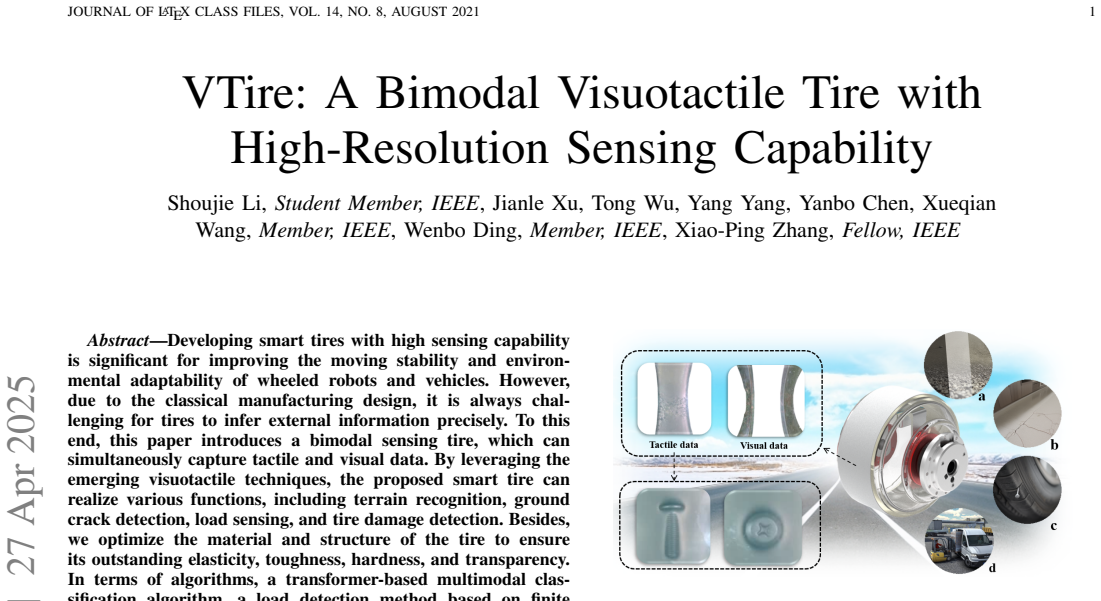
The paper's central claim is that a tire can be turned into a high-resolution visuotactile sensor by making the rolling surface transparent and elastic and watching it from inside. The VTire does this with a cast polyurethane hub, a transparent silicone layer, and a silver-powdered reflective layer; a depth camera mounted on the axle stays fixed while the tire rotates, so it continuously images the deformed contact patch plus whatever shows through the transparent sidewall. The authors build one algorithm stack on top of that image stream: a transformer that fuses tactile and visual tokens for terrain classification, a finite-element-derived deformation-to-force curve for load sensing, a fully convolutional network that segments the contact patch for cracks and dropped objects, and a damage classifier for cracks, wear, and punctures. They report 99.2% terrain classification accuracy, 98% crack segmentation accuracy, 98% object-search success, 97% damage detection accuracy, and 0.75 kg load resolution up to about 35 kg.
Load-bearing premise
The load-bearing premise is that the transparent tire materials keep enough optical clarity, marker contrast, and mechanical fidelity over the tire's lifetime that the deformation images seen while training still match what the camera sees after kilometers of driving.
Editorial extensions
If this is right
- Terrain recognition and crack or object inspection can be performed from a single internally mounted camera, with no external camera needed for the tactile functions.
- Load sensing comes from the same depth stream that measures contact deformation, so weight estimation does not require an extra force-sensor layer.
- Damage such as cracks, irregular wear, and punctures is visible in the tread's own deformation, making real-time tire health monitoring a by-product of normal driving.
- The fixed-camera, hollow-motor arrangement keeps the image source stable while the tire rotates, which makes continuous ground-facing sensing practical at low speeds.
Reading between the lines
- The durability section verifies that the tire keeps working mechanically for 200 km, but it does not quantify optical aging; measuring transmission, haze, and marker contrast over distance would show whether the sensing channel, not just the structure, lasts.
- The 0.2 mm tactile resolution is shown with calibrated needles, which suggests the tire could also act as a rolling profilometer for surface roughness or fine pavement defects; this is not a claim the paper makes.
- The fusion transformer is not tied to any particular sensor modalities, so adding wheel speed, IMU, or acoustic data is a natural next experiment; the paper only tests vision and touch.
Signed reviews
Editorial analysis
A structured set of objections, weighed in public.
Referee Report
Summary. The paper presents VTire, a transparent bimodal visuotactile tire that uses an internal camera to capture both tactile deformation images and external visual data through a transparent side region. The hardware combines a polyurethane elastic hub, a silicone transparent layer, an Eco-Flex 30/silver reflective layer, and a fixed single camera with a hollow motor drive. On the algorithmic side, the paper proposes a transformer-based multimodal fusion network (MMVTT) for terrain classification, a finite-element-assisted load sensing method based on fitted force-offset curves, and an FCN-based segmentation method for contact objects and ground cracks. The authors report a terrain classification accuracy of 99.2%, tire damage detection accuracy of 97%, object search success rate of 98%, crack segmentation accuracy of 98%, load sensing accuracy of 0.75 kg, a load capacity exceeding 35 kg, and a durability of 200 km. The paper also describes an indoor/outdoor mobile platform, datasets, and open-sourced hardware and code.
Significance. If the reported results hold, VTire is a useful integration of visuotactile sensing into a load-bearing tire, potentially enabling terrain, crack, object, damage, and load perception on wheeled robots. The hardware contribution—particularly the transparent PU hub and hollow-motor single-camera design—is interesting and the paper includes substantial real-world validation, including a 200 km durability run. The authors also provide open-source materials, which aids reproducibility. However, the evidence for some headline claims is currently uneven, and the crack-detection and load-sensing evaluations need to be clarified before the significance of the central claims can be fully assessed.
major comments (3)
- [V.D and Contributions/Abstract] The ground crack detection claim is supported only by training-set accuracy, not by held-out evaluation. Section V.D states that 'after 60 rounds of training, the training accuracy can reach 98%', yet the Contributions section claims '98% crack segmentation accuracy' and the Abstract lists ground crack detection as a realized function. Training accuracy measures fit, not generalization to unseen cracks, and without a held-out test set, pixel-level IoU, or real-world detection rate, the crack-detection component of the central claim is not substantiated. This is a metric-definition error, not merely a missing error bar.
- [V.F] The load sensing evaluation does not make clear whether the reported 0.75 kg accuracy is computed on the same data used to fit the force-offset curve or on held-out loads. Section V.F states that 'we fit the curve between force and offset using the equation' and then reports closeness to FEA; because the fit coefficients are free parameters derived from the experimental measurements, the comparison to FEA is not an independent validation. Please specify the error metric (e.g., RMSE or max error), the cross-validation or held-out protocol, and the 10 weights and 5 measurements used.
- [V.A, V.B, and V.E] Tables II and III and the damage detection results in Fig. 14 are based on 3 random seeds but no variances or confidence intervals are reported. The headline terrain classification accuracy of 99.2% is the last-10-epoch average for the EVVT configuration; without standard deviations, the reader cannot judge whether differences from baselines are significant. Please report mean and standard deviation for all metrics, or include per-seed results, for the terrain and damage classification experiments.
minor comments (5)
- [V.C] Section V.C reports 'the segmentation accuracy can reach 99%' after training the FCN on 150 images; it is ambiguous whether this is training accuracy or a held-out evaluation. Please clarify the protocol as done for the object search success rate.
- [V.G] The durability test reports qualitative statements such as 'the object search experiment still provided clear contour information' and 'crack detection resolution was stable at 0.2 mm'; to support the durability claim, please quantify the post-durability metrics and report whether optical transmission, marker contrast, or reflective layer degradation were measured.
- [III.A] The platform dimensions are stated as '60 mm long and 29 mm wide', which appears inconsistent with a platform that can 'carry adults over 70 kg'; likely this should be 60 cm and 29 cm or similar. Please correct the units.
- [VI] The conclusion contains a typo: 'bimodal smart visuotactile trie' should be 'tire'.
- [V.C and V.D] The object search experiment uses only 50 real-world trials and reports a 98% success rate; given that a single failure changes the rate by 2%, please provide the exact number of successes/trials and, if possible, a confidence interval.
Circularity Check
Crack-segmentation headline is the FCN's training-set accuracy; the remaining headline numbers are held-out or real-world and are not circular.
-
fitted input called prediction
[Section V.D (Cracks Detection Experiment); Section I Contributions bullet; Abstract]
"after 60 rounds of training, the training accuracy can reach 98%, and the cracks search results are shown in Fig. 13(b). ... Results indicate remarkable accuracy rates, including 0.75 kg weight sensing accuracy, 98% crack segmentation accuracy, 98% object detection success rate, and 97% damage detection accuracy."
The only quantitative support for the paper's crack-detection capability is the FCN's training accuracy: the contribution bullet promotes '98% crack segmentation accuracy', while Section V.D reports 'after 60 rounds of training, the training accuracy can reach 98%'. Training accuracy is computed on the same annotated images used to fit the FCN, so it measures fit to the training labels, not held-out generalization; the paper gives no test split, IoU, or real-world crack-search success rate. The headline number is therefore, by construction, a statistic of the fitted model rather than an independently predicted result.
full rationale
Terrain classification (99.2%) is evaluated on a 7:3 train/test split; damage detection uses a 70/30 split with three seeds; object search is validated by 50 real-world trials with a 98% success rate; load sensing is a fitted calibration compared with FEA, not presented as a first-principles prediction. These are independent and non-circular. The single circular step is crack detection, where the advertised accuracy is the training accuracy of the segmentation network, with no held-out evaluation. This is a partial circularity affecting one of the four headline functions, so the overall score is 6 rather than higher.
Assumptions & free parameters
free parameters (1)
- Force-offset calibration coefficients =
linear coefficients not reported
assumptions (4)
- domain assumption The FEA treats the ground as a rigid body.
- domain assumption Lab-measured material parameters (E=0.1973 MPa, nu=0.48 for hub; E=24.06 MPa, nu=0.49 for sensor layer) represent the fabricated tire in service.
- domain assumption The bearing-mounted single camera keeps a stable view of the contact patch while the tire rotates.
- domain assumption Transparent PU hub and Eco-Flex 30 reflective layer preserve optical clarity and marker contrast over the tire's lifetime.
Cite this review
Pith. "Pith review of VTire: A Bimodal Visuotactile Tire with High-Resolution Sensing Capability." pith.science (2026). https://pith.science/paper/DJPVVPC3
@misc{pith2026250419194,
  author       = {Pith},
  title        = {Pith review of: VTire: A Bimodal Visuotactile Tire with High-Resolution Sensing Capability},
  year         = {2026},
  howpublished = {\url{https://pith.science/paper/DJPVVPC3}},
  note         = {Machine review of arXiv:2504.19194}
}
read the original abstract
Developing smart tires with high sensing capability is significant for improving the moving stability and environmental adaptability of wheeled robots and vehicles. However, due to the classical manufacturing design, it is always challenging for tires to infer external information precisely. To this end, this paper introduces a bimodal sensing tire, which can simultaneously capture tactile and visual data. By leveraging the emerging visuotactile techniques, the proposed smart tire can realize various functions, including terrain recognition, ground crack detection, load sensing, and tire damage detection. Besides, we optimize the material and structure of the tire to ensure its outstanding elasticity, toughness, hardness, and transparency. In terms of algorithms, a transformer-based multimodal classification algorithm, a load detection method based on finite element analysis, and a contact segmentation algorithm have been developed. Furthermore, we construct an intelligent mobile platform to validate the system's effectiveness and develop visual and tactile datasets in complex terrains. The experimental results show that our multimodal terrain sensing algorithm can achieve a classification accuracy of 99.2\%, a tire damage detection accuracy of 97\%, a 98\% success rate in object search, and the ability to withstand tire loading weights exceeding 35 kg. In addition, we open-source our algorithms, hardware, and datasets at https://sites.google.com/view/vtire.
Figures


Figures from the paper (13 more)


Reference graph
Works this paper leans on
-
[1]
B. Yang, Q. Sun, R. Fu, C. Wang, Y . Guo, and L. Zhou, “A model predic- tive control-based electronic differential control strategy for distributed- drive buses considering the reduction of tire wear,” IEEE/ASME Trans- actions on Mechatronics , pp. 1–12, 2024
work page 2024
-
[2]
Y . Wang, T. Chen, X. Rong, G. Zhang, Y . Li, and Y . Xin, “Design and control of skater: A wheeled-bipedal robot with high-speed turn- ing robustness and terrain adaptability,” IEEE/ASME Transactions on Mechatronics, pp. 1–12, 2024
work page 2024
-
[3]
Intelligent tires? a review of tire characterization literature,
H. Lee and S. Taheri, “Intelligent tires? a review of tire characterization literature,” IEEE Intelligent Transportation Systems Magazine , vol. 9, no. 2, pp. 114–135, 2017
work page 2017
-
[4]
Tire force es- timation in intelligent tires using machine learning,
N. Xu, H. Askari, Y . Huang, J. Zhou, and A. Khajepour, “Tire force es- timation in intelligent tires using machine learning,” IEEE Transactions on Intelligent Transportation Systems , vol. 23, no. 4, pp. 3565–3574, 2020
work page 2020
-
[5]
3d printed graphene-based self-powered strain sensors for smart tires in autonomous vehicles,
D. Maurya, S. Khaleghian, R. Sriramdas, P. Kumar, R. A. Kishore, M. G. Kang, V . Kumar, H.-C. Song, S.-Y . Lee, Y . Yan, et al. , “3d printed graphene-based self-powered strain sensors for smart tires in autonomous vehicles,” Nature Communications, vol. 11, no. 1, p. 5392, 2020
work page 2020
-
[6]
Laser triangulation to measure the carcass deflections of a rolling tire,
A. J. Tuononen, “Laser triangulation to measure the carcass deflections of a rolling tire,” Measurement Science and Technology, vol. 22, no. 12, p. 125304, 2011
work page 2011
-
[7]
On-board estimation of dynamic tyre forces from opti- cally measured tyre carcass deflections,
A. Tuononen, “On-board estimation of dynamic tyre forces from opti- cally measured tyre carcass deflections,” International Journal of Heavy Vehicle Systems, vol. 16, no. 3, pp. 362–378, 2009
work page 2009
-
[8]
R. Matsuzaki, N. Hiraoka, A. Todoroki, and Y . Mizutani, “Optical 3d deformation measurement utilizing non-planar surface for the develop- ment of an “intelligent tire”,” Journal of Solid Mechanics and Materials Engineering, vol. 4, no. 4, pp. 520–532, 2010
work page 2010
Show all 39 references
-
[9]
Visuotactile sensors with emphasis on Gelsight sensor: A review,
A. C. Abad and A. Ranasinghe, “Visuotactile sensors with emphasis on Gelsight sensor: A review,” IEEE Sensors Journal , vol. 20, no. 14, pp. 7628–7638, 2020
2020
-
[10]
Dexitac: Soft dexterous tactile gripping,
C. Lu, K. Tang, M. Yang, T. Yue, H. Li, and N. F. Lepora, “Dexitac: Soft dexterous tactile gripping,” IEEE/ASME Transactions on Mechatronics , 2024
2024
-
[11]
Gelstereo biotip: Self-calibrating bionic fingertip visuotactile sensor for robotic manipulation,
S. Cui, S. Wang, C. Zhang, R. Wang, B. Zhang, S. Zhang, and Y . Wang, “Gelstereo biotip: Self-calibrating bionic fingertip visuotactile sensor for robotic manipulation,” IEEE/ASME Transactions on Mechatronics , pp. 1–12, 2023
2023
-
[12]
Estimation of tire–road friction coefficient and its application in chassis control systems,
K. B. Singh and S. Taheri, “Estimation of tire–road friction coefficient and its application in chassis control systems,” Systems Science & Control Engineering, vol. 3, no. 1, pp. 39–61, 2015
2015
-
[13]
Lateral force prediction using gaussian process regression for intelligent tire systems,
B. H. G. Barbosa, N. Xu, H. Askari, and A. Khajepour, “Lateral force prediction using gaussian process regression for intelligent tire systems,” IEEE Transactions on Systems, Man, and Cybernetics: Systems , vol. 52, no. 8, pp. 5332–5343, 2021
2021
-
[14]
Development of a high-sensitivity strain measurement system based on a sh saw sensor,
H. Oh, K. Lee, K. Eun, S.-H. Choa, and S. S. Yang, “Development of a high-sensitivity strain measurement system based on a sh saw sensor,” Journal of Micromechanics and Microengineering , vol. 22, no. 2, p. 025002, 2012
2012
-
[15]
Design considerations on intelligent tires utilizing wireless passive surface acoustic wave sensors,
X. Zhang, Z. Wang, L. Gai, Y . Ai, and F. Wang, “Design considerations on intelligent tires utilizing wireless passive surface acoustic wave sensors,” in Fifth World Congress on Intelligent Control and Automation (IEEE Cat. No. 04EX788) , vol. 4, pp. 3696–3700, 2004
2004
-
[16]
A piezo-sensor-based “smart tire
J. Yi, “A piezo-sensor-based “smart tire” system for mobile robots and vehicles,” IEEE/ASME Transactions on Mechatronics , vol. 13, no. 1, pp. 95–103, 2008
2008
-
[17]
Direct tire slip angle estimation using intelligent tire equipped with pvdf sensors,
X. Sun, Z. Quan, Y . Cai, L. Chen, and B. Li, “Direct tire slip angle estimation using intelligent tire equipped with pvdf sensors,” IEEE/ASME Transactions on Mechatronics , pp. 1–11, 2024
2024
-
[18]
A strain-based intelligent tire to detect contact patch features for complex maneuvers,
M. F. Mendoza-Petit, D. Garc ´ıa-Pozuelo, V . D´ıaz, and O. Olatunbosun, “A strain-based intelligent tire to detect contact patch features for complex maneuvers,” Sensors, vol. 20, no. 6, p. 1750, 2020
2020
-
[19]
Influence of camber angle on tire tread behavior by an on-board strain-based system for intelligent tires,
J. Yunta, D. Garcia-Pozuelo, V . Diaz, and O. Olatunbosun, “Influence of camber angle on tire tread behavior by an on-board strain-based system for intelligent tires,” Measurement, vol. 145, pp. 631–639, 2019
2019
-
[20]
Microwave-photonic sensory tire control system based on fbg,
R. Gubaidullin, T. Agliullin, O. Morozov, A. Z. Sahabutdinov, and V . Ivanov, “Microwave-photonic sensory tire control system based on fbg,” in 2019 Systems of Signals Generating and Processing in the Field of on Board Communications , pp. 1–6, 2019
2019
-
[21]
An in-wheel sensor for monitoring tire-terrain interaction: Development and laboratory testing,
R. G. Longoria, R. Brushaber, and A. Simms, “An in-wheel sensor for monitoring tire-terrain interaction: Development and laboratory testing,” Journal of Terramechanics, vol. 82, pp. 43–52, 2019
2019
-
[22]
Ter- rain classification using inside-wheel cameras based on wheel-terrain interaction characteristics,
L. Hu, F. Xue, C. Yao, Y . Li, J. Wei, P. Wang, Z. Zhu, and Z. Jia, “Ter- rain classification using inside-wheel cameras based on wheel-terrain interaction characteristics,” in 2023 IEEE International Conference on Robotics and Biomimetics (ROBIO) , pp. 1–6, 2023
2023
-
[23]
A road condition classification algorithm for a tire acceleration sensor using an artificial neural network,
H.-J. Kim, J.-Y . Han, S. Lee, J.-R. Kwag, M.-G. Kuk, I.-H. Han, and M.- H. Kim, “A road condition classification algorithm for a tire acceleration sensor using an artificial neural network,” Electronics, vol. 9, no. 3, p. 404, 2020
2020
-
[24]
Terrain classification using intelligent tire,
S. Khaleghian and S. Taheri, “Terrain classification using intelligent tire,” Journal of Terramechanics, vol. 71, pp. 15–24, 2017
2017
-
[25]
Highly sensitive surface acoustic wave strain sensor for the measurement of tire deformation,
K. Eun, K. J. Lee, K. K. Lee, S. S. Yang, and S.-H. Choa, “Highly sensitive surface acoustic wave strain sensor for the measurement of tire deformation,” International Journal of Precision Engineering and Manufacturing, vol. 17, pp. 699–707, 2016
2016
-
[26]
Where shall i touch? vision-guided tactile poking for transparent object grasping,
J. Jiang, G. Cao, A. Butterworth, T.-T. Do, and S. Luo, “Where shall i touch? vision-guided tactile poking for transparent object grasping,” IEEE/ASME Transactions on Mechatronics, vol. 28, no. 1, pp. 233–244, 2023
2023
-
[27]
Attention is all you need,
A. Vaswani, N. Shazeer, N. Parmar, J. Uszkoreit, L. Jones, A. N. Gomez, Ł. Kaiser, and I. Polosukhin, “Attention is all you need,” Advances in Neural Information Processing Systems , vol. 30, 2017
2017
-
[28]
Layer normalization,
J. Ba, J. R. Kiros, and G. E. Hinton, “Layer normalization,” ArXiv, vol. abs/1607.06450, 2016
2016 arXiv
-
[29]
Visuo-tactile transformers for manipulation,
Y . Chen, A. Sipos, M. V . der Merwe, and N. Fazeli, “Visuo-tactile transformers for manipulation,” in Conference on Robot Learning, 2022
2022
-
[30]
Deep residual learning for image recognition,
K. He, X. Zhang, S. Ren, and J. Sun, “Deep residual learning for image recognition,” 2016 IEEE Conference on Computer Vision and Pattern Recognition (CVPR), pp. 770–778, 2015
2016
-
[31]
Fully convolutional networks for semantic segmentation,
J. Long, E. Shelhamer, and T. Darrell, “Fully convolutional networks for semantic segmentation,” in IEEE Conference on Computer Vision and Pattern Recognition (CVPR), pp. 3431–3440, 2015
2015
-
[32]
Convolutional LSTM network: A machine learning approach for precipitation nowcasting,
X. Shi, Z. Chen, H. Wang, D. Y . Yeung, W.-K. Wong, and W. chun Woo, “Convolutional LSTM network: A machine learning approach for precipitation nowcasting,” in Neural Information Processing Systems , 2015
2015
-
[33]
An image is worth 16x16 words: Transformers for image recognition at scale,
A. Dosovitskiy, L. Beyer, A. Kolesnikov, D. Weissenborn, X. Zhai, T. Unterthiner, M. Dehghani, M. Minderer, G. Heigold, S. Gelly, et al., “An image is worth 16x16 words: Transformers for image recognition at scale,” arXiv preprint arXiv:2010.11929 , 2020. 11
2010 arXiv
-
[34]
Extended vision transformer (exvit) for land use and land cover classification: A mul- timodal deep learning framework,
J. Yao, B. Zhang, C. Li, D. Hong, and J. Chanussot, “Extended vision transformer (exvit) for land use and land cover classification: A mul- timodal deep learning framework,” IEEE Transactions on Geoscience and Remote Sensing , vol. 61, pp. 1–15, 2023
2023
-
[35]
3d vision technologies for a self-developed structural external crack damage recognition robot,
K. Hu, Z. Chen, H. Kang, and Y . Tang, “3d vision technologies for a self-developed structural external crack damage recognition robot,” Automation in Construction , vol. 159, p. 105262, 2024
2024
-
[36]
Obstacle avoidance motion in mobile robotics,
Y . Tang, S. Qi, L. Zhu, X. Zhuo, Y . Zhang, and F. Meng, “Obstacle avoidance motion in mobile robotics,” Journal of System Simulation , vol. 36, no. 1, pp. 1–26, 2024
2024
-
[37]
Durability of tires
“Durability of tires.” https://www.deccanherald.com/sports/f1- racing/lasting-little-60km-tyres-are-716735.html
-
[38]
Extend- ing the lifespan of tires,
S. L. Weissman, J. L. Sackman, D. Gillen, and C. Monismith, “Extend- ing the lifespan of tires,” Sympletic Engineering Corporation. Institute for Transportation Studies. University of California at Berkeley , 2003. Shoujie Li received the B.Eng. degree in elec- tronic informat...
2003
-
[2023]
degree in Tsinghua-Berkeley Shenzhen Institute, Tsinghua University, Shenzhen, China
He is current working toward the Ph.D. degree in Tsinghua-Berkeley Shenzhen Institute, Tsinghua University, Shenzhen, China. His research interests include robot manipulation, multimodal sensing, and embodied intelligence. Yang Yang is currently an undergraduate student at Sic...
2025
Reviewed August 16, 2026 · model on record in the stance chip above.
Discussion (0). Continue with ORCID to comment.