REVIEW 5 major objections 4 minor 2 cited by
Towards Navigation-Grade and Deployable Optomechanical Accelerometry
T0 review · 5 major / 4 minor · reviewed 2026-08-15 · deepseek-v4-flash
Pith's one-line read This paper claims that an optomechanical accelerometer built around a differential strain-sensing Mach-Zehnder interferometer on a bulk-micromachined proof mass reaches navigation-grade bias stability, with a projected path to 330 ng/√Hz.
desk verdict Strong new architecture, solid NEA/bandwidth results, but the 6.3 µg bias instability is not established as an inertial bias—navigation-grade claim is premature. read the letter →
The pith
A machine-rendered reading of the paper's core claim, the machinery that carries it, and where it could break.
The reading
What carries the argument
The load-bearing object is the DSMZI-on-BMPM: a differential strain-sensing Mach-Zehnder interferometer (DSMZI) integrated on the surface of a bulk-micromachined proof mass (BMPM), with waveguides routed along the sensing tethers so that proof-mass displacement becomes strain and a differential optical phase. The proof mass is intentionally ultra-rigid, at a 93.4 kHz fundamental resonance (22.5 pm/g), and the key identities are the sub-resonant susceptibility $\mathrm{d}x/\mathrm{d}a \approx 1/\Omega_s^2$ and the ratio $\frac{\mathrm{d}x/\mathrm{d}a}{\mathrm{d}x/\mathrm{d}F_B} = m$, which show that a heavier proof mass suppresses body-force and package-stress drift. The differential phase is $\Delta\phi = 2[k\chi a + \Delta(kL)_{PE} + \Delta(kL)_{MB}]$, where the photoelastic and moving-boundary terms capture strain-induced changes in the propagation constant. A finite-element model evaluates those terms from the exact strain profile and predicts the acceleration-to-power responsivity and noise floors. The differential geometry is what cancels common laser, thermal, and packaging drift while keeping the readout broadband.
What would settle it
Re-run the bias-instability test with balanced detection and a power-stabilized laser while continuously monitoring the laser output; if the floor near 243 s moves with laser power or disappears, the claimed $6.3\ \mu\mathrm{g}$ belongs to the optical readout, not to the accelerometer.
Extended reading notes
Core claim
The central discovery is that a navigation-grade optomechanical accelerometer does not need a high-Q optical resonator; sensitivity can come from an interferometric strain readout on a deliberately stiff proof mass. The device is a 16.7 mg silicon proof mass suspended by tethers, with a 93.4 kHz fundamental resonance; acceleration displaces it by 22.5 pm/g, and the tether strain is measured by a silicon-nitride DSMZI whose arms wrap the tethers up to four times. Because the readout is differential, common-mode effects such as laser frequency drift, temperature changes, and package stress partially cancel, and because the proof mass is large, displacement per unit body force is small, which suppresses bias drift. The measured off-resonance resolution is $4.2\ \mu\mathrm{g}/\sqrt{\mathrm{Hz}}$ over 66 kHz, the optical bandwidth is 17 nm, the temperature range exceeds 20 °C, the projected dynamic range is 165.4 dB, and the measured bias instability is $6.3\ \mu\mathrm{g}$ at 243.4 s for the two-pass device ($20.3\ \mu\mathrm{g}$ at 579.3 s for the four-pass device). The model predicts a shot-noise-limited floor of $1.15\ \mu\mathrm{g}/\sqrt{\mathrm{Hz}}$ at 10 mW per detector, so the reported performance is claimed to be limited by insertion loss and amplifier noise rather than by the sensing principle.
Load-bearing premise
The load-bearing premise is that the measured $6.3\ \mu\mathrm{g}$ Allan floor is a true acceleration bias of the sensor rather than drift of the single-ended photodiode readout, since the run had no balanced detection, no laser intensity stabilization, and ambient air.
Editorial extensions
If this is right
- Navigation-grade thresholds—about $1\ \mu\mathrm{g}/\sqrt{\mathrm{Hz}}$ resolution and below $10\ \mu\mathrm{g}$ bias instability—become reachable for chip-scale optomechanical accelerometers without vacuum, cryogenic cooling, or laser locking.
- Geometric scaling of the same design covers resonances from below 50 kHz to 1 MHz, giving projected resolutions from $0.259\ \mu\mathrm{g}/\sqrt{\mathrm{Hz}}$ to $31.3\ \mu\mathrm{g}/\sqrt{\mathrm{Hz}}$ for vibrometry, impact testing, and condition monitoring.
- Because the optical bandwidth is 17 nm, the sensor can run on a simple fixed-wavelength laser, eliminating the tunable, frequency-stabilized source and control electronics that block deployment of cavity-based designs.
- Improved fiber-chip coupling and balanced detection should lower the noise floor to about $330\ \mathrm{ng}/\sqrt{\mathrm{Hz}}$, approaching the $130\ \mathrm{ng}/\sqrt{\mathrm{Hz}}$ thermomechanical limit of the 105 kHz design.
- The architecture points toward vibratory Coriolis gyroscopes: adding piezoelectric actuators to drive motion orthogonal to the sense mode could extend the same low-drift readout to rotation-rate sensing for GPS-free navigation.
Reading between the lines
- Editorial inference: if the $6.3\ \mu\mathrm{g}$ floor persists in a balanced-detection run, this sensor enters the bias-instability class of commercial navigation-grade MEMS accelerometers.
- Editorial inference: the fitted velocity random walk of $89.2\ \mu\mathrm{g}/\sqrt{\mathrm{Hz}}$ versus the measured $4.2\ \mu\mathrm{g}/\sqrt{\mathrm{Hz}}$ NEA implies a slow optical noise source dominated the Allan run; a reference photodiode would settle that.
- Beyond the paper, a decisive environmental test is to sweep temperature across the full $>20$ °C range while keeping wavelength in the 17 nm band and logging Allan deviation; sub-$10\ \mu\mathrm{g}$ bias throughout would prove deployability.
- Beyond the paper, the 'heavy stiff proof mass plus differential strain readout' rule likely transfers to optomechanical force, pressure, and magnetometry sensors, though no such demonstration is included here.
Signed reviews
Editorial analysis
A structured set of objections, weighed in public.
Referee Report
Summary. The paper presents an optomechanical accelerometer architecture based on a differential strain-sensing Mach–Zehnder interferometer (DSMZI) integrated on a bulk-micromachined proof mass (BMPM) with a 93.4 kHz resonant frequency. The authors report an off-resonance noise-equivalent acceleration (NEA) of 4.2 µg/√Hz over a 66 kHz bandwidth, a 6.3 µg bias instability at 243 s for a two-pass device, a 17 nm optical bandwidth, a >20 °C temperature operating range, and a projected dynamic range of 165.4 dB. They argue that the combination of high rigidity and differential optical readout makes the sensor insensitive to common causes of bias instability and thereby constitutes a path toward navigation-grade, deployable optomechanical accelerometers.
Significance. If the bias instability result were established as a true acceleration bias, the reported 6.3 µg value would be the lowest for an optomechanical accelerometer and would represent a meaningful step toward navigation-grade performance. The work also demonstrates a useful design principle—using a high-stiffness proof mass with an integrated differential interferometer—that broadens the optical and temperature operating bandwidths relative to cavity-based devices. The experimental characterization is substantial, including wavelength and temperature scans, Allan deviation measurements, and a comparison with prior work. The central limitation is that the bias instability claim is not yet convincingly separated from optical readout drift, and the projected performance figures (330 ng/√Hz, 165.4 dB dynamic range) are not measured but extrapolated.
major comments (5)
- [Appendix F.3, Section II] The Allan deviation analysis reports a fitted velocity random walk (VRW) of 89.2 µg/√Hz for the four-pass device, while the same device's NEA is 4.2 µg/√Hz. If the white noise in the Allan run were the accelerometer's acceleration noise, these two quantities should be equal. The 21-fold excess indicates that the Allan measurement was dominated by an unidentified noise source—likely laser intensity noise or polarization drift in the single-ended photodiode readout—rather than by acceleration noise. Consequently, the bias instability minimum at 579.3 s (20.3 µg) inherits this contamination and cannot be attributed to an inertial bias without additional discriminating measurements.
- [Section II, Appendix E] The bias instability measurement was performed with a single-ended photodiode on one interferometer output, without balanced detection, laser intensity stabilization, or polarization control. The DSMZI's differential readout suppresses common-mode strain but does not reject laser RIN or power drift in a single output. Appendix E concedes that intensity stabilization and polarization-maintaining fibers would be needed to improve bias instability, which is consistent with the interpretation that the measured Allan deviation minimum is readout-limited rather than acceleration-limited. The manuscript should directly address this and provide a test that distinguishes optical readout drift from true acceleration bias.
- [Table III, Section II] The 6.3 µg bias instability is obtained from the two-pass device, which has an NEA of 29 µg/√Hz and a path-length mismatch of 27.9 µm, whereas the four-pass device has an NEA of 4.2 µg/√Hz but a bias instability of 20.3 µg. The fact that the less sensitive device shows the lower Allan minimum suggests the result may reflect wavelength sensitivity or scale-factor drift rather than an intrinsic inertial property. The paper should explain why the two-pass device's Allan minimum is more than three times lower despite its larger NEA.
- [Appendix G, Section III] The claimed dynamic range of 165.4 dB is based on the projected 330 ng/√Hz noise floor, not on the measured NEA of 4.2 µg/√Hz. Using the measured NEA, the dynamic range would be approximately 143 dB at 1 Hz bandwidth. Moreover, the experimentally demonstrated linear dynamic range is 81.6 dB, limited by the actuator. The abstract and discussion should not present 165.4 dB as an experimentally supported value without clearly labeling it as a projection.
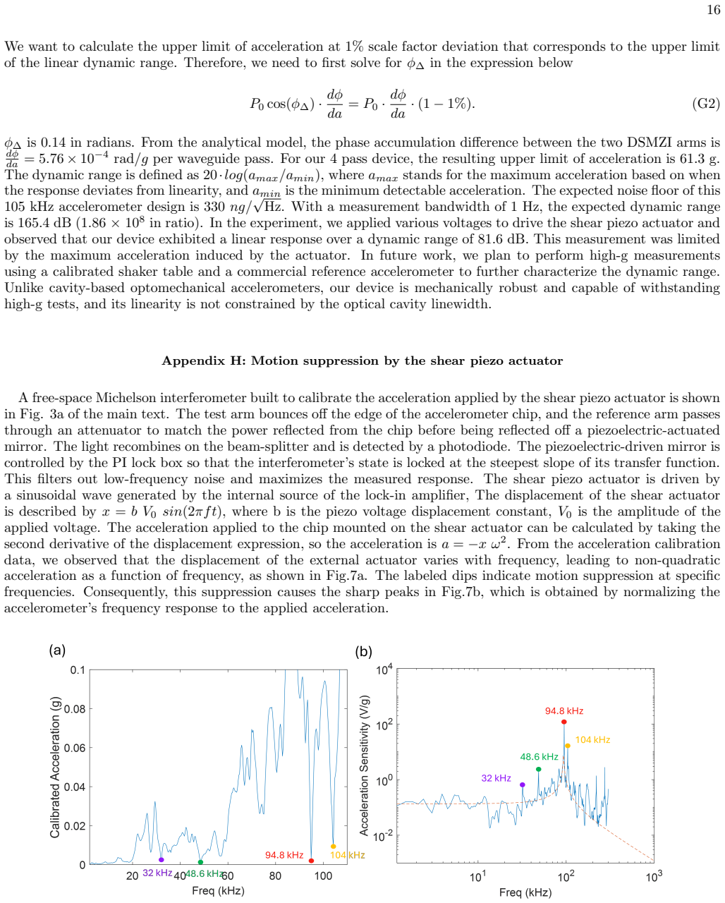
- [Section II, Appendix C] The measured acceleration responsivity is reported to be within a factor of 5.6 of the FEM prediction, yet this factor is not discussed. Since the projected path to 330 ng/√Hz and the dynamic-range calculation both rely on the model's phase sensitivity (5.76×10⁻⁴ rad/g per pass), the authors should quantify the uncertainty this discrepancy introduces into the projected performance and explain whether it originates from the optical model, the mechanical model, or the calibration.
minor comments (4)
- [Section I] There is a typo in the sentence 'This optimization leads to optimizng the ratio'—'optimizng' should be 'optimizing'.
- [Appendix A] Equation (A2) appears to be missing factors of the mass in the damping and spring terms; as written it is dimensionally inconsistent with the Langevin equation in (A1).
- [Figure 3 caption] The caption states that the Allan deviation shows a minimum at 579.3 seconds, but Section II reports both 579.3 s (four-pass) and 243.4 s (two-pass) values. The caption should specify that it refers to the four-pass device to avoid ambiguity.
- [Table I] The table lists 'Our devices' with two values in parentheses for several columns, but the footnote only explains asterisks; a brief legend would clarify that the parenthetical values correspond to the two-pass device.
Circularity Check
No significant circularity: headline metrics are direct measurements, and the FEM phase-sensitivity model is independently compared rather than fitted.
full rationale
The paper's central claims are experimental measurements: NEA of 4.2 µg/√Hz, bias instability of 20.3/6.3 µg, 66 kHz operational bandwidth, >20 °C temperature range, and optical bandwidth of 5/17 nm. These are obtained directly from photodiode, lock-in, PSD, and Allan-deviation measurements; none are outputs of a fitted model. The FEM model predicts a phase sensitivity of 5.76e-4 rad/g per pass from geometry, photoelastic constants, and moving-boundary effects, and the measured responsivity is compared with this prediction and found to disagree by a factor of 5.6, so the model is not being tuned to reproduce the measurement. The theoretical NEA values are computed from shot, detector, and thermal noise formulas with stated assumptions (e.g., 10 mW per detector, balanced detection) and are not used to produce the measured 4.2 µg/√Hz value. The 165.4 dB dynamic range is an explicitly 'expected' projection based on the modeled scale factor and a projected 330 ng/√Hz noise floor, while the measured dynamic range of 81.6 dB is separately reported. The self-citations [8,9] support the differential-readout insensitivity argument, but that argument is also backed in this paper by direct wavelength and temperature scans and by Eq. (2), so the citations are not load-bearing. The VRW/NEA mismatch noted in Appendix F.3 is a validity concern about optical-readout noise contamination, not a circular derivation. Therefore no load-bearing step reduces by construction to its own input.
Assumptions & free parameters
free parameters (3)
- Mechanical Q-factor =
54.3
- Effective path-length mismatch (4-pass device) =
121.4 µm
- Effective path-length mismatch (2-pass device) =
27.9 µm
assumptions (7)
- standard math The accelerometer's mechanical response is a 1-DoF damped harmonic oscillator (Eq. A1-A3).
- domain assumption The sense mode at 93 kHz is the lowest-frequency mechanical mode driven by acceleration, so the sub-resonant response is undistorted (Section I, Eq. 1).
- standard math Fluctuation-dissipation theorem relates thermal force noise to mechanical damping (Eq. B2).
- standard math Photoelastic and moving-boundary perturbation theory describes strain-induced phase shifts in the waveguides (Eq. C3-C4).
- domain assumption The MZI output follows P = P0 sin²((Δφ+π/2)/2) and operates near quadrature (Eq. D1-D3).
- domain assumption The free-space Michelson interferometer accurately calibrates the acceleration applied to the device (Appendix H).
- ad hoc to paper The bias instability measured on a single-ended photodiode output represents the accelerometer's acceleration bias (Appendix F.3).
Cite this review
Pith. "Pith review of Towards Navigation-Grade and Deployable Optomechanical Accelerometry." pith.science (2026). https://pith.science/paper/3NVPMPX5
@misc{pith2026250511751,
  author       = {Pith},
  title        = {Pith review of: Towards Navigation-Grade and Deployable Optomechanical Accelerometry},
  year         = {2026},
  howpublished = {\url{https://pith.science/paper/3NVPMPX5}},
  note         = {Machine review of arXiv:2505.11751}
}
abstract
We design and experimentally demonstrate an architecture for achieving navigation-grade, fiber-packaged optomechanical accelerometers that can operate with a large dynamic range, over a wide temperature range, and without sophisticated laser sources. Our accelerometer architecture is based on a novel set of design principles that take advantage of the strengths of optomechanical accelerometry while eliminating many of its historical weaknesses. Displacement readout is provided by an integrated, differential strain-sensing Mach-Zehnder interferometer (DSMZI) attached to an ultra-rigid, bulk-micromachined proof mass having a 93.4 kHz fundamental resonance frequency (22.5 pm/g displacement). Despite the extreme rigidity, the high displacement sensitivity provides an insertion loss limited 4.2 $\mu g/\sqrt{\mathrm{Hz}}$ acceleration resolution, with a straight-forward path to achieving 330 $n g/\sqrt{\mathrm{Hz}}$ by improving the fiber-to-chip coupling. Further, we show that the combination of high rigidity and intrinsic differential optical readout makes the device insensitive to the common causes of bias instability, and we measure a bias instability of 6.3 $\mu g$ at 243 seconds. The DSMZI provides a 17 nm optical bandwidth and a temperature operating range of greater than 20 $^\circ\mathrm{C}$, both orders of magnitude larger than previous demonstrations of optomechanical accelerometers. The high rigidity and large optical bandwidth yield an expected dynamic range of 165.4 dB. The combination of high acceleration resolution, high dynamic range, low bias instability, and intrinsic insensitivity to wavelength, temperature, and package stresses makes our device well suited for deployment in realistic environments demanded by real-world applications and demonstrates a path for optomechanical accelerometers to ultimately exceed the performance of all other chip-based accelerometers.
Figures


Figures from the paper (4 more)


Forward citations
Cited by 2 Pith papers
-
Precision optomechanical accelerometer via hybrid test mass integration
A pick-and-place bonded 95 mg platinum sphere on a silicon nitride trampoline yields a chip-integrated accelerometer with 5.5 ng/√Hz peak sensitivity at 117 Hz in air.
-
Optomechanical Accelerometer Search for Ultralight Dark Matter
A 39 kHz optomechanical membrane accelerometer was operated at 4 K to search for ultralight vector dark matter, yielding no signal and upper limits weaker than existing equivalence-principle bounds.
Reference graph
Works this paper leans on
-
[1]
A. G. Krause, M. Winger, T. D. Blasius, Q. Lin, and O. Painter, Nature Photonics 6, 768 (2012)
work page 2012
-
[2]
What is an inertial navigation system?
VectorNav Technologies, “What is an inertial navigation system?” (2023), accessed: 2025-05-13
work page 2023
-
[3]
Defense Advanced Research Projects Agency (DARPA), “Higher-Order Composite Resonators for Extra Resilience (HORCREX): Broad agency announce- ment (hr001124s0039),” https://sam.gov/opp/ fdc0f3e41f2948f4b8cf0d574ec39ecb/view (2024), accessed: May 13, 2025
work page 2024
-
[4]
Y. L. Li and P. Barker, Journal of Lightwave Technology 36, 3919 (2018)
work page 2018
-
[5]
L. Jin, C. Wang, L. Jin, W. Chen, H. Xu, M. Cui, and M. Li, Applied Optics 61, 5386 (2022)
work page 2022
- [6]
-
[7]
O. Gerberding, F. G. Cervantes, J. Melcher, J. R. Pratt, and J. M. Taylor, Metrologia 52, 654 (2015)
work page 2015
-
[8]
D. Dominguez, L. Hackett, M. Miller, J. Restrepo, K. Casper, and M. Eichenfield, in 2021 IEEE Interna- tional Symposium on Inertial Sensors and Systems (IN- ERTIAL) (IEEE, 2021) pp. 1–4
work page 2021
Show all 33 references
-
[9]
C. Ge, D. Dominguez, M. Miller, and M. Eichenfield, in Frontiers in Optics (Optica Publishing Group, 2024) pp. FW1D–3
2024
-
[10]
Murphy, Analog Devices, Inc (2020)
C. Murphy, Analog Devices, Inc (2020)
2020
-
[11]
Tandon and K
N. Tandon and K. Kumar, Noise & Vibration Worldwide 34, 9 (2003)
2003
-
[12]
H. G. Espinosa, J. Lee, and D. A. James, Journal of Fitness Research 4, 13 (2015)
2015
-
[13]
L. B. Soldano and E. C. Pennings, Journal of lightwave technology 13, 615 (1995)
1995
-
[14]
Sheng, Z
Z. Sheng, Z. Wang, C. Qiu, L. Li, A. Pang, A. Wu, X. Wang, S. Zou, and F. Gan, IEEE Photonics Jour- nal 4, 2272 (2012)
2012
-
[15]
S. G. Johnson, M. Ibanescu, M. Skorobogatiy, O. Weis- berg, J. Joannopoulos, and Y. Fink, Physical review E 65, 066611 (2002)
2002
-
[16]
Appendix d: Elasticity, photoelasticity, and electrooptic effects,
C. Chen, “Appendix d: Elasticity, photoelasticity, and electrooptic effects,” (2006)
2006
-
[17]
H. Tian, J. Liu, A. Attanasio, A. Siddharth, T. Bl´ esin, R. Ning Wang, A. Voloshin, G. Lihachev, J. Riemens- berger, S. E. Kenning, et al. , Advances in Optics and Photonics 16, 749 (2024)
2024
-
[18]
Murphy, Analog dialogue 51, 1 (2017)
C. Murphy, Analog dialogue 51, 1 (2017)
2017
-
[19]
Mehmet, S
M. Mehmet, S. Ast, T. Eberle, S. Steinlechner, H. Vahlbruch, and R. Schnabel, Optics express 19, 25763 (2011)
2011
-
[20]
Y. Xia, A. R. Agrawal, C. M. Pluchar, A. J. Brady, Z. Liu, Q. Zhuang, D. J. Wilson, and Z. Zhang, Nature Photonics 17, 470 (2023). 8
2023
-
[21]
F. Zhou, Y. Bao, R. Madugani, D. A. Long, J. J. Gorman, and T. W. LeBrun, Optica 8, 350 (2021)
2021
-
[22]
Guzm´ an Cervantes, L
F. Guzm´ an Cervantes, L. Kumanchik, J. Pratt, and J. M. Taylor, Applied Physics Letters 104 (2014)
2014
-
[23]
D. Long, J. Stroud, B. Reschovsky, Y. Bao, F. Zhou, S. Bresler, T. LeBrun, D. Plusquellic, and J. Gorman, APL Photonics 8 (2023)
2023
-
[24]
P. R. Saulson, Physical Review D 42, 2437 (1990)
1990
-
[25]
Johnson, N
K. Johnson, N. Alshamrani, D. Almutairi, A. Grieco, C. Horvath, J. N. Westwood-Bachman, A. McKinlay, and Y. Fainman, Optics Express 30, 46134 (2022)
2022
-
[26]
Silicon (si) - properties, applications,
AZoM, “Silicon (si) - properties, applications,” https:// www.azom.com/properties.aspx?ArticleID=53 (2001), accessed: 2025-05-02
2001
-
[27]
AVAR (Adaptive Vector Autoregression) [MATLAB GUI],
E. Ogier, “AVAR (Adaptive Vector Autoregression) [MATLAB GUI],” https://www.mathworks.com/ matlabcentral/fileexchange/ (2025). 9 Table I. Summary of the specifications of optomechanical accelerometers reported in the literature Paper Mass (mg) fs (kHz) Q-factor Operational Ban...
2025
-
[28]
The Fth is a random force with a white spectrum density added to Fext shown in (A1), it can be expressed as Fth 2 = 4kBTf
Noise from thermal Brownian motion Thermal noise is one of the fundamental limits to the precision of mechanical measurements. The Fth is a random force with a white spectrum density added to Fext shown in (A1), it can be expressed as Fth 2 = 4kBTf. (B1) Where kB is Boltzmann’...
-
[29]
(B3) Where dP da is the scale factor of the device, ω0 is the optical frequency of light, and Ptot is the total power on the detector
Shot and detector noises Shot noise is generated by the dc power hitting the photodiode, it can be expressed by ashot = (dP da )−1 s 2ℏω0Ptot ηqe . (B3) Where dP da is the scale factor of the device, ω0 is the optical frequency of light, and Ptot is the total power on the dete...
-
[30]
The Power Spectral Density (PSD) in dBm/Hz can be expressed as PSD = 10 log10 V 2 rms Z × 1000 − 10 log10(BW)
Optical power spectral density measurements We use a lock-in amplifier to measure the photodiode output voltage in Vrms with a time constant of 100 ms and an impedance Z of 50 Ω. The Power Spectral Density (PSD) in dBm/Hz can be expressed as PSD = 10 log10 V 2 rms Z × 1000 − 1...
-
[31]
In the case of Fabry–P´ erot microcavity accelerometers, the FWHM can be directly calculated as the free spectral range (FSR) divided by the cavity finesse
Optical bandwidth analysis For cavity-based optomechanical accelerometers, the 3 dB optical bandwidth is equivalent to the optical full width at half maximum (FWHM). In the case of Fabry–P´ erot microcavity accelerometers, the FWHM can be directly calculated as the free spectr...
-
[32]
The laser cavity detuning induced by a change in temperature is ∆th =gth∆To, (F1) where gth is the thermo-optical tuning coefficient
T emperature bound For an example of the temperature range that can be expected from a resonator-based optomechanical accelerometer, we follow the temperature analysis given in [1]. The laser cavity detuning induced by a change in temperature is ∆th =gth∆To, (F1) where gth is ...
-
[33]
The overlapped Allan deviation is computed using the MATLAB AVAR GUI [27], which is also used to fit and extract various noise coefficients
Bias instability and Allan deviation To measure bias instability, the accelerometer is placed in an acoustically shielded enclosure under ambient condi- tions (in air at room temperature) without external acceleration applied. The overlapped Allan deviation is computed using t...
Reviewed August 15, 2026 · model on record in the stance chip above.
Discussion (0). Continue with ORCID to comment.