Recognition: 2 theorem links
· Lean TheoremTransient Stability of GFL Converters Subjected to Switching of Droop-Controlled GFM Converters
Pith reviewed 2026-05-14 22:47 UTC · model grok-4.3
The pith
The stability boundary of the switched GFL-GFM system coincides with the current-limit control subsystem, and a local virtual fixed d-axis control strategy restores convergence to constant-voltage mode.
A machine-rendered reading of the paper's core claim, the machinery that carries it, and where it could break.
Core claim
The switched system's stability boundary coincides with that of the CLC subsystem. To enhance GFLC's transient stability and ensure GFMC converges to the CVC mode, this paper introduces a virtual fixed d-axis control (VFDC) strategy that achieves decoupling and self-stabilization using only local state variables from individual converters.
What carries the argument
Virtual fixed d-axis control (VFDC) strategy that fixes the d-axis reference from local converter states to decouple GFL and GFM dynamics during mode switching.
If this is right
- Stability margins for GFL converters can be designed from the CLC boundary alone even when GFMs switch modes.
- The VFDC method removes the need for communication links between converters to achieve stabilization.
- GFM units are driven out of current-limit mode during transients, reducing sustained stress on the network.
- Subsystem analysis of the CLC mode supplies a conservative bound for the entire switched system.
Where Pith is reading between the lines
- If switching is strictly angle-dependent, then GFL angle oscillations directly tighten the effective stability margin by triggering GFM mode changes.
- The local-only VFDC approach may scale to large inverter fleets without centralized coordination.
- Similar local decoupling could be tested on other switching events such as fault ride-through or protection actions.
Load-bearing premise
The switched system can be modeled with angle-dependent triggers so that stability of the full system reduces to stability of the current-limit subsystem without major unmodeled interactions.
What would settle it
A test case in which the full switched system becomes unstable at an operating point inside the CLC stability boundary, or in which VFDC fails to drive the GFM converter back to CVC using only local variables.
Figures


read the original abstract
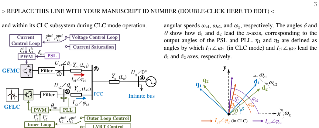
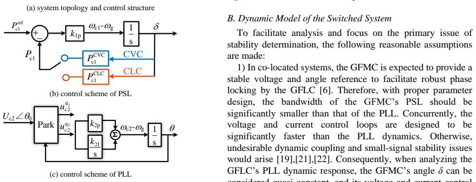
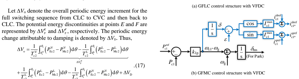
Integrating grid-forming converters (GFMCs) into grid-following converter (GFLC)-dominated power systems enhances the grid strength, but GFMCs' current-limiting characteristic triggers dynamic switching between constant voltage control (CVC) and current limit control (CLC). This switching feature poses critical transient stability risks to GFLCs, requiring urgent investigation. This paper first develops a mathematical model for this switched system. Then, it derives switching conditions for droop-controlled GFMCs, which are separately GFMC angle-dependent and GFLC angle-dependent. On this basis, the stability boundaries of GFLC within each subsystem are analyzed, and the impact of GFMC switching arising from GFLC angle oscillation is investigated. The findings reveal that the switched system's stability boundary coincides with that of the CLC subsystem. To enhance GFLC's transient stability and ensure GFMC converges to the CVC mode, this paper introduces a virtual fixed d-axis control (VFDC) strategy. Compared with existing methods, this method achieves decoupling and self-stabilization using only local state variables from individual converters. The conclusions are validated through simulations and Controller Hardware-in-the-Loop tests.
Editorial analysis
A structured set of objections, weighed in public.
Referee Report
Summary. The paper develops a mathematical model for the switched system of grid-following converters (GFLCs) interacting with droop-controlled grid-forming converters (GFMCs) that dynamically switch between constant voltage control (CVC) and current limit control (CLC) modes. It derives GFMC-angle-dependent and GFLC-angle-dependent switching conditions, analyzes GFLC stability boundaries in each subsystem, finds that the overall switched-system stability boundary coincides with the CLC subsystem, and proposes a virtual fixed d-axis control (VFDC) strategy that achieves decoupling and self-stabilization using only local converter states. Results are validated by simulations and Controller Hardware-in-the-Loop tests.
Significance. If the stability-boundary coincidence holds and the VFDC provides the claimed decoupling without new instability modes, the work would be significant for transient-stability analysis of mixed GFL-GFM systems and for supplying a practical, local-only control fix that avoids communication or global measurements.
major comments (1)
- [stability analysis section] The central claim that the switched system's stability boundary coincides with that of the CLC subsystem (abstract and stability-analysis section) rests on the unverified assumption that angle-triggered hybrid transitions introduce no new instability modes via dwell-time effects, chattering, or grid-mediated interactions. Separate subsystem analysis is insufficient; the manuscript should supply either explicit dwell-time bounds or a hybrid Lyapunov function to confirm that CVC intervals cannot destabilize trajectories already at the CLC limit.
minor comments (1)
- [Abstract] The abstract states that conclusions are validated through simulations and CHIL tests but provides no quantitative metrics (e.g., critical clearing times, oscillation damping ratios, or parameter ranges), making it difficult to judge the practical margin of the reported improvement.
Simulated Author's Rebuttal
We thank the referee for the constructive and detailed comments. We agree that a rigorous treatment of the hybrid switched-system dynamics is essential to fully support the central stability-boundary claim. In the revised manuscript we will augment the stability-analysis section with an explicit hybrid Lyapunov function and dwell-time bounds derived from the angle dynamics, confirming that CVC intervals cannot destabilize trajectories already at the CLC limit.
read point-by-point responses
-
Referee: [stability analysis section] The central claim that the switched system's stability boundary coincides with that of the CLC subsystem (abstract and stability-analysis section) rests on the unverified assumption that angle-triggered hybrid transitions introduce no new instability modes via dwell-time effects, chattering, or grid-mediated interactions. Separate subsystem analysis is insufficient; the manuscript should supply either explicit dwell-time bounds or a hybrid Lyapunov function to confirm that CVC intervals cannot destabilize trajectories already at the CLC limit.
Authors: We appreciate this observation. The manuscript derives GFMC- and GFLC-angle-dependent switching conditions and shows, via subsystem Lyapunov functions and extensive simulation/CHIL validation, that trajectories reaching the CLC boundary remain inside the region of attraction of the CVC subsystem upon switching back; no chattering or grid-mediated instabilities appear in the tested cases. Nevertheless, we acknowledge that a complete hybrid stability argument is required. In revision we will construct a hybrid Lyapunov function by combining the individual subsystem functions with a dwell-time condition obtained from the bounded rate of angle change under the proposed VFDC. This will rigorously demonstrate that CVC intervals cannot push the state outside the CLC stability region. revision: yes
Circularity Check
Derivation chain self-contained; stability boundary result obtained from switched-system model without reduction to inputs
full rationale
The paper first constructs an explicit switched-system model incorporating angle-dependent switching conditions for both GFMC and GFLC. It then separately computes the stability boundaries of the GFLC within the CVC and CLC subsystems and compares them to the full switched trajectory. The reported coincidence is presented as an outcome of this comparison rather than a definitional identity or a fitted parameter renamed as prediction. The VFDC strategy is introduced as an additional local control law whose decoupling property is verified by simulation, not presupposed in the model. No load-bearing self-citation, uniqueness theorem imported from prior work, or ansatz smuggled via citation appears in the derivation steps. The analysis therefore remains independent of its own conclusions.
Axiom & Free-Parameter Ledger
free parameters (1)
- Switching thresholds
axioms (2)
- domain assumption Droop control law governs GFMC voltage and frequency response
- domain assumption Current limit control activates precisely under overcurrent conditions
invented entities (1)
-
Virtual fixed d-axis control (VFDC)
no independent evidence
Lean theorems connected to this paper
-
IndisputableMonolith/Foundation/RealityFromDistinction.leanreality_from_one_distinction unclear?
unclearRelation between the paper passage and the cited Recognition theorem.
The findings reveal that the switched system's stability boundary coincides with that of the CLC subsystem... Lyapunov function V = ½Tϖ² + ∫(P_E - P_M)dθ
-
IndisputableMonolith/Cost/FunctionalEquation.leanwashburn_uniqueness_aczel unclear?
unclearRelation between the paper passage and the cited Recognition theorem.
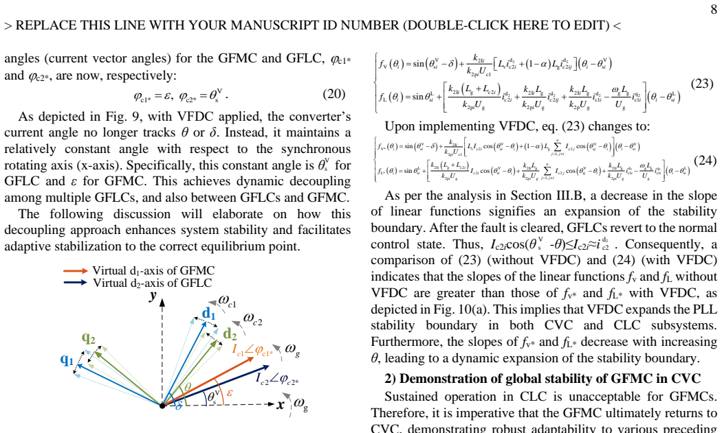
switching conditions... GFMC angle-dependent and GFLC angle-dependent... phasor diagrams ΓV, ΓL1, ΓL2
What do these tags mean?
- matches
- The paper's claim is directly supported by a theorem in the formal canon.
- supports
- The theorem supports part of the paper's argument, but the paper may add assumptions or extra steps.
- extends
- The paper goes beyond the formal theorem; the theorem is a base layer rather than the whole result.
- uses
- The paper appears to rely on the theorem as machinery.
- contradicts
- The paper's claim conflicts with a theorem or certificate in the canon.
- unclear
- Pith found a possible connection, but the passage is too broad, indirect, or ambiguous to say the theorem truly supports the claim.
Reference graph
Works this paper leans on
-
[1]
M. G. Taul, X. Wang, P. Davari, and F. Blaabjerg, “An Overview of Assessment Methods for Synchronization Stability of Grid -Connected Converters Under Severe Symmetrical Grid Faults,” IEEE Trans. Power Electron., vol. 34, no. 10, pp. 9655–9670, Oct. 2019
work page 2019
-
[2]
Multi -Swing Transient Stability of Synchronous Generators and IBR Combined Generation Systems,
S. Yang et al., "Multi -Swing Transient Stability of Synchronous Generators and IBR Combined Generation Systems," IEEE Trans. Power Syst., vol. 40, no. 1, pp. 1144-1147, Jan. 2025
work page 2025
-
[3]
Grid-Synchronization Stability of Converter -Based Resources —An Overview,
X. Wang, M. G. Taul, H. Wu, Y. Liao, F. Blaabjerg, and L. Harnefors, “Grid-Synchronization Stability of Converter -Based Resources —An Overview,” IEEE Open J. Ind. Appl., vol. 1, pp. 115–134, 2020
work page 2020
-
[4]
Blackout hits Spain and Portugal: what happened and what’s next,
C. Canestrini, “Blackout hits Spain and Portugal: what happened and what’s next,” Florence School of Regulation. Accessed: Jun. 10 , 2025. [Online]. Available: https://fsr.eui.eu/blackout -hits-spain-and-portugal- what-happened-and-whats-next/
work page 2025
-
[5]
K. Strunz, K. Almunem, C. Wulkow, M. Kuschke, M. Valescudero, and X. Guillaud, “Enabling 100% Renewable Power Systems Through Power Electronic Grid-Forming Converter and Control: System Integration for Security, Stability, and Application to Europe,” Proc. IEEE, vol. 111, no. 7, pp. 891–915, Jul. 2023
work page 2023
-
[6]
H. Xin, C. Liu, X. Chen, Y. Wang, E. Prieto-Araujo, and L. Huang, “How Many Grid-Forming Converters Do We Need? A Perspective From Small Signal Stability and Power Grid Strength,” IEEE Trans. Power Syst., vol. 40, no. 1, pp. 623–635, Jan. 2025. 14 > REPLACE THIS LINE WITH YOUR MANUSCRIPT ID NUMBER (DOUBLE-CLICK HERE TO EDIT) <
work page 2025
-
[7]
Transient Stability of Droop - Controlled Inverter Networks With Ope rating Constraints,
K. D. Smith, S. Jafarpour, and F. Bullo, “Transient Stability of Droop - Controlled Inverter Networks With Ope rating Constraints,” IEEE Trans. Automat. Contr., vol. 67, no. 2, pp. 633–645, Feb. 2022.L
work page 2022
-
[8]
Analysis and Improvement of Transient Voltage Stability for Grid -Forming Converters,
J. Fang, W. Si, L. Xing, and S. M. Goetz, “Analysis and Improvement of Transient Voltage Stability for Grid -Forming Converters,” IEEE Trans. Ind. Electron., vol. 71, no. 7, pp. 7230–7240, Jul. 2024
work page 2024
-
[9]
Y. Zhang, C. Zhang, R. Yang, M. Molinas, and X. Cai, “Cur rent- Constrained Power -Angle Characterization Method for Transient Stability Analysis of Grid -Forming Voltage Source Converters,” IEEE Trans. Energy Convers, vol. 38, no. 2, pp. 1338–1349, Jun. 2023
work page 2023
-
[10]
Fault Recovery Analysis of Grid-Forming Inverters With Priority-Based Current Limiters,
B. Fan and X. Wang, “Fault Recovery Analysis of Grid-Forming Inverters With Priority-Based Current Limiters,” IEEE Trans. Power Syst., vol. 38, no. 6, pp. 5102-5112, Nov. 2023
work page 2023
-
[11]
Huang, H. Xin, Z. Wang, L. Zhang, K. Wu, and J. Hu, “Transient stability analysis and control design of droop-controlled voltage source converters considering current limitation,” IEEE Trans. Smart Grid , vol. 10, no. 1, pp. 578–591, Jan. 2019
work page 2019
-
[12]
C. Shen, Z. Shuai, Y. Pend, X. Liu, Z. Li, and J. Shen, “Transient Stability and Current Injection Design of Paralleled Current -Controlled VSCs and Virtual Synchronous Generators,” IEEE Trans. Smart Grid ., vol. 12, no. 2, pp. 1118–1134, Mar. 2021
work page 2021
-
[13]
Transient Stability of Paralleled Virtual Synchronous Generator and Grid-Following Inverte r,
P. Me, M. H. Ravanji, M. Z. Mansour, S. Zabihi, and B. Bahrani, “Transient Stability of Paralleled Virtual Synchronous Generator and Grid-Following Inverte r,” IEEE Trans. Smart Grid ., vol. 14, no. 6, pp. 4451–4466, Nov. 2023
work page 2023
-
[14]
Transient Stability Analysis and Enhancement of Grid-Forming and Grid-Following Converters,
C. Xu, Z. Zou, J. Yang, Z. Wang, W. Chen, and G. Buticchi, “Transient Stability Analysis and Enhancement of Grid-Forming and Grid-Following Converters,” IEEE J. Emerg. Sel. Topics Ind. Electron., vol. 5, no. 4, pp. 1396–1408, Oct. 2024
work page 2024
-
[15]
S. Chen, J. Yao, Y. Liu, J. Pei, S. Huang, and Z. Chen, “Coupling Mechanism Analysis and Transient Stability Assessment for Multiparalleled Wind Farms During LVRT,” IEEE Trans. Sustain. Energy, vol. 12, no. 4, pp. 2132–2145, Oct. 2021
work page 2021
-
[16]
X. Yi et al., “Transient Synchronization Stability Analysis and Enhancement of Paralleled Converters Considering Different Current Injection Strategies,” IEEE Trans. Sustain. Energy , vol. 13, no. 4, pp. 1957–1968, Oct. 2022
work page 1957
-
[17]
Current Saturation Analysis and Anti-Windup Control Design of Grid-Forming Voltage Source Converter,
K. Zhuang, H. Xin, P. Hu, and Z. Wang, “Current Saturation Analysis and Anti-Windup Control Design of Grid-Forming Voltage Source Converter,” IEEE Trans. Energy Convers., vol. 37, no. 4, pp. 2790–2802, Dec. 2022
work page 2022
-
[18]
Transient Stability of Power Synchronization Loop Based Grid Forming Converter,
Y. Li, Y. Lu, X. Yuan, R. Yang, S. Yang, H . Ye, and Z. Du, “Transient Stability of Power Synchronization Loop Based Grid Forming Converter,” IEEE Trans. Energy Convers., vol. 38, no. 4, pp. 2843–2859, Dec. 2023
work page 2023
-
[19]
Review of control techniques for inverters parallel operation,
A. Mohd, E. Ortjohann, D. Morton, and O. Omari, “Review of control techniques for inverters parallel operation,” Electr. Power Syst. Res., vol. 80, no. 12, pp. 1477–1487, Dec. 2010
work page 2010
-
[20]
J. Liu et al., "Multiobjective adaptive predictive virtual synchronous generator control strategy for grid stability and renewable integration," Sci. Rep., vol. 15, article 93721, 2025
work page 2025
-
[21]
J. Shang, J. Yu, Z. Liu, S. Wang, J. Li, and J, Liu, “Accurate Frequency - domain Modeling and Simplified Stability Criterion for Parallel Grid - forming and Grid-following Inverter System,” Autom. Electr. Power Syst., pp. 1–23, Dec. 2024
work page 2024
-
[22]
Transient Stability Analysis of Hybrid GFL -GFM System Considering Various Damping Effects,
Q. Qu, X. Xiang, K. Xin, Y. Liu, W. Li, and X. He, “Transient Stability Analysis of Hybrid GFL -GFM System Considering Various Damping Effects,” IEEE Trans. Ind. Electron., pp. 1–14, 2025
work page 2025
-
[23]
C. Wu, Y. Lyu, Y. Wang, and F. Blaabjerg, “Transient Synchronization Stability Analysis of Grid-Following Converter Considering the Coupling Effect of Current Loop and Phase Locked Loop,” IEEE Trans. Energy Convers, vol. 39, no. 1, pp. 544–554, Mar. 2024
work page 2024
-
[24]
B. Li et al., "Entire Period Transient Stability of Synchronous Generators Considering LVRT Switching of Nearby Renewable Energy Sources," IEEE Trans. Power Syst., doi: 10.1109/TPWRS.2025.3614478
-
[25]
Direct me thod of Lyapunov applied to synchronization stability of VSC with phase-locked loop,
Y. Li, Y. Lu, and Z. Du, “Direct me thod of Lyapunov applied to synchronization stability of VSC with phase-locked loop,” Electr. Power Syst. Res., vol. 220, p. 109376, Jul. 2023
work page 2023
-
[26]
Multi-swing PLL Synchronization Transient Stability of G rid-Connected Paralleled Converters,
Z. Wang, L. Guo, X. Li, X. Zhou, J. Zhu, and C. Wang, “Multi-swing PLL Synchronization Transient Stability of G rid-Connected Paralleled Converters,” IEEE Trans. Sustain. Energy, pp. 1–13, 2024
work page 2024
-
[27]
Ö. Göksu, R. Teodorescu, C. L. Bak, F. Iov, and P. C. Kjær, “Instability of Wind Turbine Converters During Current Injection to Low Voltage Grid Faults and PLL Frequency Based Stability Solution,” IEEE Trans. Power Syst., vol. 29, no. 4, pp. 1683–1691
-
[28]
Grid -Synchronization Stability Improvement of Large Scale Wind Farm During Severe Grid Fault,
S. Ma, H. Geng, L. Liu, G. Yang, and B. C. Pal, “Grid -Synchronization Stability Improvement of Large Scale Wind Farm During Severe Grid Fault,” IEEE Trans. Power Syst. ,yang vol. 33, no. 1, pp. 216 –226, Jan. 2018. Bingfang Li (Member, IEEE), received the B.S. degree from North China Electric Power University, Baoding, China, in 2022, and is currently wo...
work page 2018
discussion (0)
Sign in with ORCID, Apple, or X to comment. Anyone can read and Pith papers without signing in.