Recognition: 2 theorem links
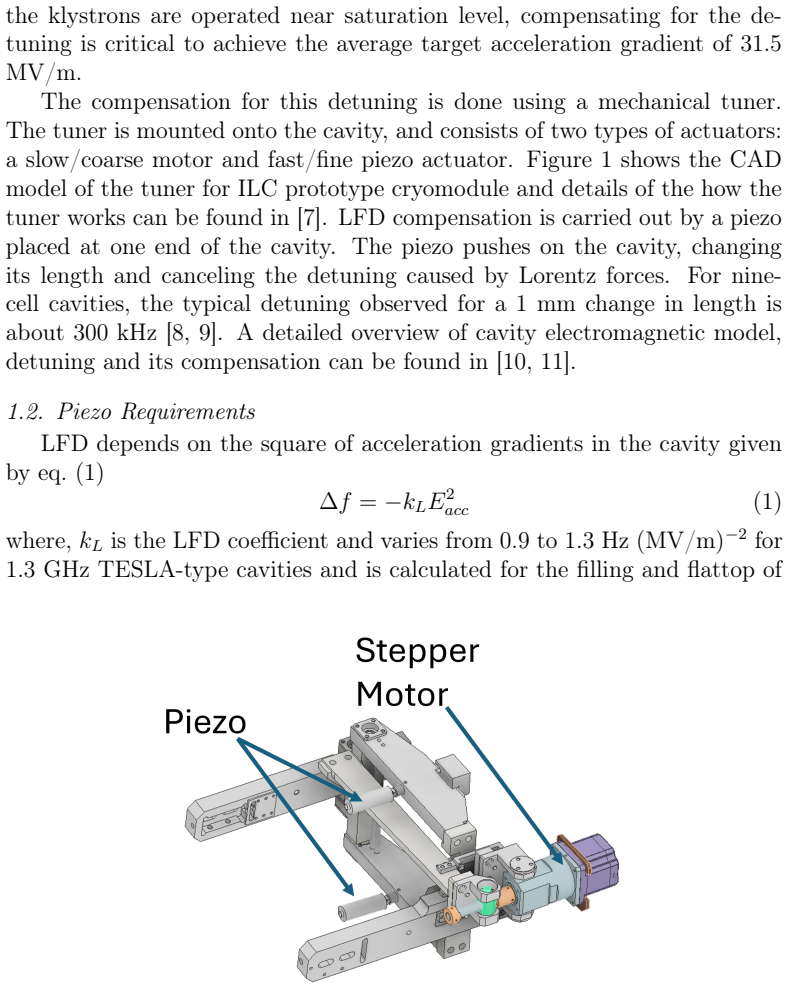
· Lean TheoremDirect stroke measurement of Piezos for cavity frequency tuner of the ILC prototype cryomodule using a Laser Displacement Sensor
Pith reviewed 2026-05-10 20:15 UTC · model grok-4.3
The pith
A laser displacement sensor measures piezo actuator stroke directly at cryogenic temperatures in vacuum.
A machine-rendered reading of the paper's core claim, the machinery that carries it, and where it could break.
Core claim
We developed a new method for the direct and precise measurement of piezo stroke at cryogenic temperature inside a cryocooler-cooled cryostat using a laser displacement sensor. The setup was used to characterize and evaluate two piezo actuators for cavity frequency tuners of the ILC prototype cryomodule.
What carries the argument
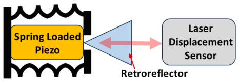
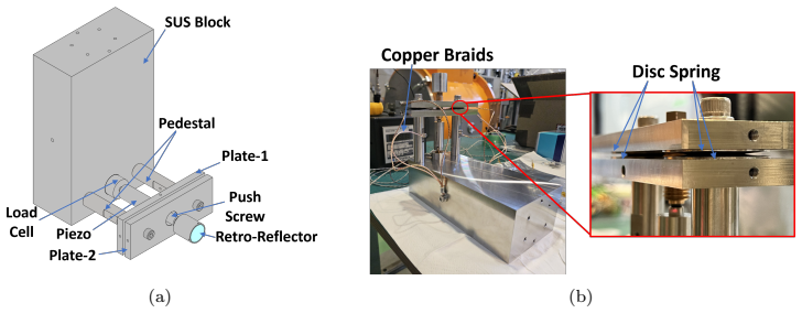
Laser displacement sensor mounted to record the mechanical extension of the piezo actuator while the assembly is held in vacuum and cooled to cryogenic temperatures inside the cryostat.
If this is right
- Piezo actuators can be selected or rejected for ILC-type cryomodules on the basis of their actual cold stroke rather than room-temperature specifications.
- Characterization campaigns become faster and cheaper because the cavity itself is not required as a measurement transducer.
- The same hardware can be used to compare multiple piezo designs or to monitor stroke degradation after thermal cycling.
- Performance data obtained this way directly informs the required stroke margin for maintaining cavity resonance under high-gradient operation.
Where Pith is reading between the lines
- The method could be adapted for in-situ verification inside a fully assembled operating cryomodule if optical access is provided.
- Standardizing this laser-based protocol might reduce variability in piezo qualification across different accelerator laboratories.
- Long-term reliability predictions for ILC tuners would improve if stroke data from this technique were combined with endurance tests under repeated detuning cycles.
Load-bearing premise
The laser sensor reports the true mechanical stroke without systematic errors introduced by the vacuum, low temperature, or the mounting arrangement itself.
What would settle it
Simultaneous or repeated measurements of the same piezo at 4 K that differ by more than the stated sensor uncertainty from independent room-temperature extrapolations or from capacitance-based estimates would falsify the claim of direct, accurate cryogenic measurement.
Figures


read the original abstract
Piezoelectric actuators are critical for achieving high accelerating gradients and preventing RF trips in narrow-bandwidth superconducting radio-frequency (SRF) cavities by compensating for detuning caused by Lorentz force detuning. Depending on the maximum acceleration gradient an appropriate piezo stroke requirement has to be fulfilled. Since the stroke of piezo actuators decreases at cryogenic temperatures, evaluating their performance under such conditions is essential. Common characterization methods either use the SRF cavity itself as a sensor or rely on capacitance measurements during cool-down. Both these approaches do not measure the stroke directly and involve a trade-off between measurement precision and experimental simplicity, as well as cost and time. We developed a new method for the direct and precise measurement of piezo stroke at cryogenic temperature inside a cryocooler-cooled cryostat using a laser displacement sensor. The setup was used to characterize and evaluate two piezo actuators for cavity frequency tuners of the ILC prototype cryomodule, which is currently being built at KEK. In this article we are reporting on the development, setup, test, and application of this novel method, allowing the direct stroke measurement of piezos in vacuum and at cryogenic temperatures.
Editorial analysis
A structured set of objections, weighed in public.
Referee Report
Summary. The paper presents a new experimental method for directly measuring the stroke of piezoelectric actuators at cryogenic temperatures inside a vacuum cryocooler-cooled cryostat, using a commercial laser displacement sensor. The setup is applied to characterize two specific piezo actuators intended for the cavity frequency tuners of the ILC prototype cryomodule under construction at KEK. The authors argue that this approach avoids the precision-simplicity trade-offs of indirect methods that rely on the SRF cavity resonance or capacitance sensing during cool-down.
Significance. A validated direct-measurement technique for piezo stroke under realistic cryogenic and vacuum conditions would be useful for SRF cavity tuner design in projects such as the ILC, where accurate knowledge of reduced stroke at low temperature is required to meet detuning-compensation specifications. The work is primarily methodological and could serve as a practical reference if accompanied by quantitative performance data.
major comments (3)
- [Abstract] Abstract: the repeated claim of a 'direct and precise measurement' is not accompanied by any numerical stroke values, uncertainty budgets, or comparison data (e.g., room-temperature vs. cryo results or cross-check against a capacitance gauge). This absence makes the central precision claim impossible to evaluate from the given text.
- [Setup] Setup description: no independent validation or error budget is reported for the laser displacement sensor under simultaneous vacuum and cryogenic conditions. Systematic effects from thermal contraction of optics/mounts, refractive-index changes, or sensor-specification drift are not quantified or cross-calibrated against a reference standard.
- [Setup] Mechanical integration: the manuscript does not present data or an explicit test confirming that the sensor mounting and target attachment leave the piezo mechanically unconstrained (i.e., do not add measurable stiffness or friction that would reduce the observed free stroke).
minor comments (2)
- [Abstract] The abstract and introduction would benefit from a brief quantitative statement of the expected piezo-stroke reduction at 4 K versus room temperature, drawn from manufacturer data or prior literature, to set the scale of the measurement challenge.
- [Method] Figure captions and method text should explicitly state the model number and manufacturer-specified resolution/accuracy of the laser sensor, together with the sampling rate and any filtering applied during data acquisition.
Simulated Author's Rebuttal
We thank the referee for the careful and constructive review of our manuscript. We address each major comment point by point below, indicating where revisions will be incorporated.
read point-by-point responses
-
Referee: [Abstract] Abstract: the repeated claim of a 'direct and precise measurement' is not accompanied by any numerical stroke values, uncertainty budgets, or comparison data (e.g., room-temperature vs. cryo results or cross-check against a capacitance gauge). This absence makes the central precision claim impossible to evaluate from the given text.
Authors: We agree that the abstract would be strengthened by including key quantitative results. The full manuscript reports measured stroke values for the two piezo actuators at both room temperature and cryogenic conditions, along with the observed reduction factor and sensor-based uncertainty estimates. In the revised version we will update the abstract to include representative stroke numbers, the temperature dependence, and a statement on measurement precision. revision: yes
-
Referee: [Setup] Setup description: no independent validation or error budget is reported for the laser displacement sensor under simultaneous vacuum and cryogenic conditions. Systematic effects from thermal contraction of optics/mounts, refractive-index changes, or sensor-specification drift are not quantified or cross-calibrated against a reference standard.
Authors: The sensor is a commercial unit whose specifications are cited in the manuscript. While room-temperature and cryogenic tests were performed, we acknowledge that a dedicated uncertainty budget quantifying all combined vacuum-cryogenic systematics (thermal contraction, refractive-index shifts, drift) was not presented. We will add an explicit uncertainty analysis section in the revision, providing estimates derived from material data and sensor documentation. revision: yes
-
Referee: [Setup] Mechanical integration: the manuscript does not present data or an explicit test confirming that the sensor mounting and target attachment leave the piezo mechanically unconstrained (i.e., do not add measurable stiffness or friction that would reduce the observed free stroke).
Authors: The mounting was designed with a lightweight target and minimal-contact geometry to preserve free-stroke conditions. We did not include a dedicated verification measurement or quantitative stiffness check. In the revision we will expand the mechanical-integration description to detail the design rationale and will add any available supporting observations from the existing test data. revision: partial
Circularity Check
No circularity: experimental methods paper with no derivation or fitting
full rationale
The paper describes the development, setup, testing, and application of a laser displacement sensor method for direct piezo stroke measurement at cryogenic temperatures in vacuum. It contains no mathematical derivation chain, no fitted parameters presented as predictions, no self-citations used as load-bearing uniqueness theorems, and no ansatz or renaming of known results. All claims rest on physical apparatus description and reported measurements rather than any reduction to inputs by construction. This is a standard experimental methods report whose central claim (direct measurement feasibility) is independent of any self-referential logic.
Axiom & Free-Parameter Ledger
axioms (1)
- domain assumption The stroke of piezo actuators decreases at cryogenic temperatures
Lean theorems connected to this paper
-
IndisputableMonolith/Foundation/AbsoluteFloorClosure.leanreality_from_one_distinction unclearWe developed a new method for the direct and precise measurement of piezo stroke at cryogenic temperature inside a cryocooler-cooled cryostat using a laser displacement sensor.
-
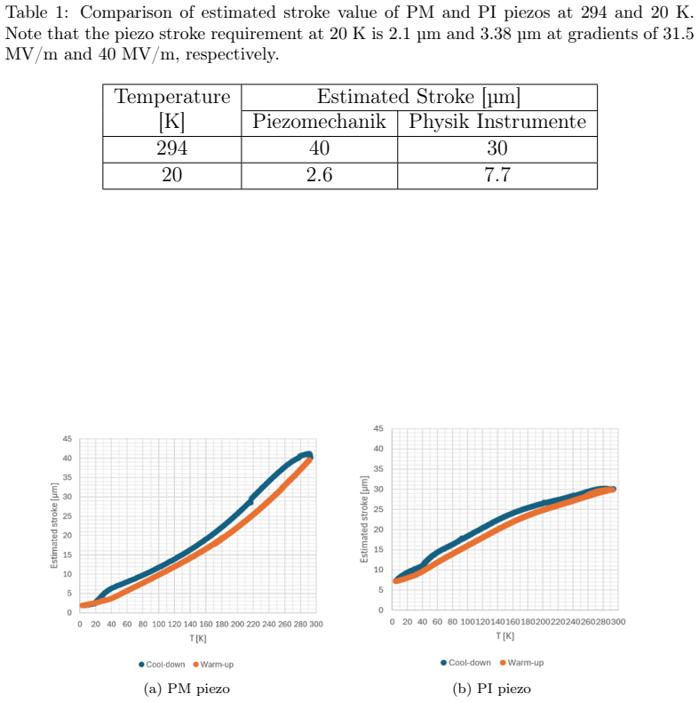
IndisputableMonolith/Cost/FunctionalEquation.leanwashburn_uniqueness_aczel unclearThe stroke of PM piezo was measured to be 43 µm at 294 K and drops by 96.3% to 1.6 µm at 20 K.
Reference graph
Works this paper leans on
- [1]
-
[2]
The International Linear Collider: A Global Project
P. Bambade,et al., “The International Linear Collider: A Global Project”, 2019.https://doi.org/10.48550/arXiv.1903.01629 14
-
[3]
L. Evans and S. Michizono “The International Linear Collider Machine Staging Report 2017”, 2017.https://doi.org/10.48550/arXiv.1711. 00568
-
[4]
Improved Formalism for Precision Higgs Coupling Fits
T. Barklowet al., “Improved Formalism for Precision Higgs Coupling Fits”,Phys. Rev. D, vol. 97, 053003, 2018.https://doi.org/10.1103/ PhysRevD.97.053003
2018
-
[5]
Status of the subsystems fo the ILC prototype cry- omodule at KEK
M. Ometet al., “Status of the subsystems fo the ILC prototype cry- omodule at KEK”,Presentation, LCWS2025., 2025
2025
-
[6]
Instability in the walls of a cavity due to pon- deromotive forces of the electromagnetic field
M. M. Karlineret al., “Instability in the walls of a cavity due to pon- deromotive forces of the electromagnetic field”,Sov. Phys. Tech. Phys., 11, 1501 1967
1967
-
[7]
Status of the SRF Cavity Tuner for the MEXT-ATD / ITN Cryomodule Being Built at KEK
M. Ometet al., “Status of the SRF Cavity Tuner for the MEXT-ATD / ITN Cryomodule Being Built at KEK”,Poster, SRF 2025, 2025
2025
-
[8]
PERFORMANCE OF SRF CAVITY TUNERS AT LCLS II PROTOTYPE CRYOMODULE AT FNAL
J. Holzbaueret al., “PERFORMANCE OF SRF CAVITY TUNERS AT LCLS II PROTOTYPE CRYOMODULE AT FNAL”,Proceedings at LINAC 2016, 2016
2016
-
[9]
Cryomodule tests of four Tesla-like cavities in the Su- perconducting RF Test Facility at KEK
E. Kakoet al., “Cryomodule tests of four Tesla-like cavities in the Su- perconducting RF Test Facility at KEK”,Phys. Rev. Accel. Beams, vol. 13, 041002, 2010.https://doi.org/10.1103/PhysRevSTAB.13.041002
-
[10]
Real-time cavity simulator and tuner control system for the ITN Cryomodule at KEK
R. Bajpai, T. Matsumoto and M. Omet “Real-time cavity simulator and tuner control system for the ITN Cryomodule at KEK”,Proceedings of SRF 2025, 2025
2025
-
[11]
Real-time cavity simulator-based low-level radio- frequency test bench and applications for accelerators
F. Qiuet al., “Real-time cavity simulator-based low-level radio- frequency test bench and applications for accelerators”,Phys. Rev. Accel. Beams, vol. 21, 032003, 2018.https://doi.org/10.1103/ PhysRevAccelBeams.21.032003
2018
-
[12]
3D multiphysics modeling of superconducting cav- itieswithamassivelyparallelsimulationsuite
O. Kononenkoet al., “3D multiphysics modeling of superconducting cav- itieswithamassivelyparallelsimulationsuite”,Phys. Rev. Accel. Beams, 20, 102001 2017.https://doi.org/10.1103/PhysRevAccelBeams.20. 102001 15
-
[13]
Study of different piezoelectric mate- rial stroke displacement at different temperatures using an SRF cav- ity
C. Contreras-Martinezet al., “Study of different piezoelectric mate- rial stroke displacement at different temperatures using an SRF cav- ity”,Proceedings of SRF 2023, 2023.https://proceedings.jacow. org/srf2023/papers/wepwb134.pdf
2023
-
[14]
Reliability of the LCLS II SRF Cavity Tuner
Y. Pischalnikovet al., “Reliability of the LCLS II SRF Cavity Tuner”, SRF 2015, 2015
2015
-
[15]
PERFORMANCE EVALUATION OF KEK ERL MAIN LINAC TUNER
K. Enamiet al., “PERFORMANCE EVALUATION OF KEK ERL MAIN LINAC TUNER ”,Proceedings of the 10th Annual Meeting of Particle Accelerator Society of Japan, 2013
2013
-
[16]
[Online]
Ono Sokki,Laser Doppler Vibrometer, Yokohama, Japan. [Online]. Available:https://www.onosokki.co.jp/HP-WK/products/keisoku/ thickness/lv9300a.html
-
[17]
L. E. Drain,The Laser Doppler Technique. Wiley, 1980. 16
1980
discussion (0)
Sign in with ORCID, Apple, or X to comment. Anyone can read and Pith papers without signing in.