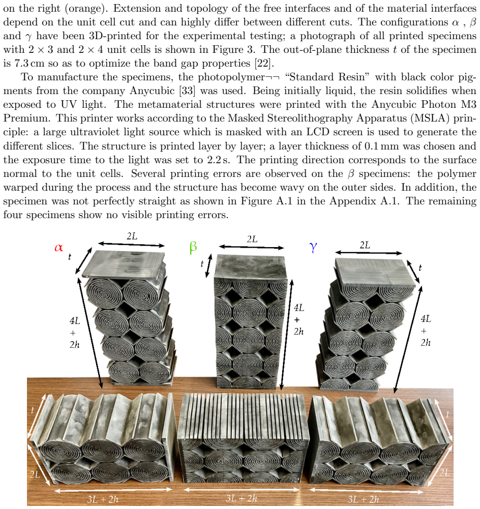
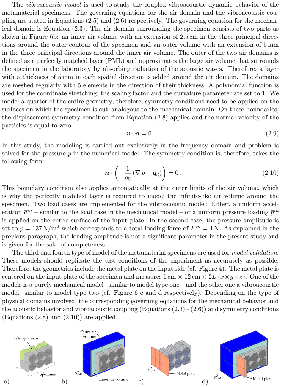
Recognition: unknown
Unveiling the key role of Interfaces in the Design of finite-sized Metamaterial Structures
Pith reviewed 2026-05-07 11:36 UTC · model grok-4.3
The pith
Optimizing the cuts at metamaterial-plate interfaces can shift finite structures from underperforming to outperforming classical vibration dampers.
A machine-rendered reading of the paper's core claim, the machinery that carries it, and where it could break.
Core claim
The central claim is that material interfaces (arising from different unit-cell cuts at the metamaterial/plate boundary) and free interfaces strongly govern the global vibration response, local displacement fields, and vibroacoustic coupling of finite-sized sandwich metamaterial structures, even though all four cuts produce the identical infinite periodic metamaterial; optimizing these interfaces plus the adjacent homogeneous plates enables the finite structure to achieve significantly better damping than classical benchmark solutions.
What carries the argument
The material interfaces created by different unit-cell cuts at the metamaterial/plate boundary, which fix the connection geometry while leaving the bulk periodic response unchanged.
If this is right
- Different interface types produce distinct global vibration transmission characteristics in the finite sandwich structures.
- The strength and character of vibroacoustic coupling depends on the chosen metamaterial/plate interface.
- Local displacement fields inside the metamaterial array vary with interface design.
- Interface optimization together with plate design can raise damping performance above that of classical civil-engineering solutions.
- These effects appear in both experimental measurements and validated finite-element models of the tested configurations.
Where Pith is reading between the lines
- Metamaterial design for real engineering parts should treat the boundary cut as a primary design variable on equal footing with the repeating cell geometry.
- The same interface sensitivity may limit or enable performance in other finite-domain metamaterial uses such as acoustic isolation or energy harvesting.
- Periodic-boundary simulations that ignore interfaces will systematically miss the performance that can be reached (or lost) in actual limited-size devices.
- The approach suggests that simple geometric rules for choosing the cut could be derived to guide interface selection without exhaustive testing.
Load-bearing premise
The four unit-cell cuts produce identical infinite metamaterials yet allow the finite vibration responses to be tuned independently through interface choice alone.
What would settle it
Finding identical vibration transmission spectra and damping levels across all four differently cut finite sandwich specimens would falsify the claim that interface type controls the performance difference.
Figures


read the original abstract
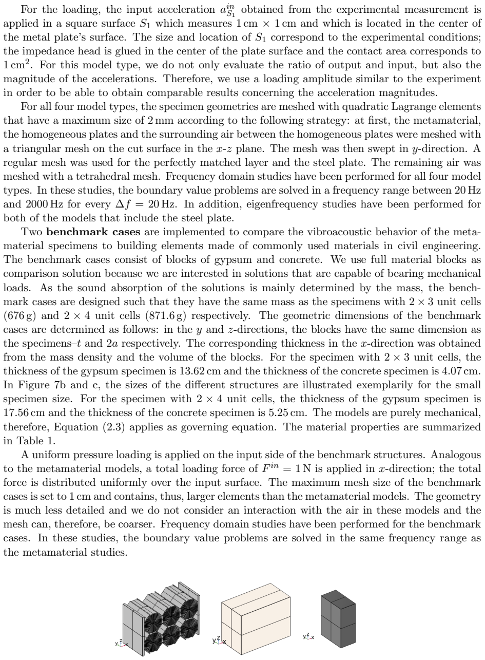
This paper investigates the influence of interfaces on the performance of finite-sized mechanical metamaterial structures for vibration damping applications. The metamaterial structures are designed in a sandwich configuration in which two homogeneous plates are connected to a metamaterial array. We test four different arrays that are obtained from the same metamaterial by differently cutting the metamaterial's unit cell at the metamaterial/plate interface. When the four unit cells are periodically repeated in space, they create the same infinitely large metamaterial with an identical mechanical response. In finite-sized structures, however, the different interfaces between the metamaterial array and the plates~--~called ``material interfaces''~--~and between the metamaterial and the air~--~called ``free interfaces''~--~strongly affect the specimen's vibration transmission characteristics. Using experimental measurements and validated finite-element (FE) models, we demonstrate a significant influence of the different types of interfaces on the global responses and local displacement fields of the structures. We also demonstrate the presence of a vibroacoustic coupling in the structures which also depends on the type of metamaterial/plate interfaces. Furthermore, we explore optimization strategies for enhancing the vibration damping performance of the metamaterial structures considering not only the metamaterial array but also the adjacent structures (the homogeneous plates). A comparison with benchmark cases illustrates the optimization potential that the interfaces' design offers for the vibration damping capability of finite-sized metamaterial structures. We show that optimizing the type of targeted interfaces can shift a metamaterial's response from underperforming to significantly outperforming compared to classical solutions for noise and vibration damping in civil engineering.
Editorial analysis
A structured set of objections, weighed in public.
Referee Report
Summary. The paper investigates the role of material and free interfaces in finite-sized sandwich metamaterial structures for vibration damping. Four arrays are obtained by different cuts of the same unit cell at the metamaterial/plate boundary; these cuts are asserted to yield identical infinite periodic metamaterials but produce distinctly different finite-structure vibration transmission and vibroacoustic responses. Experiments and validated FE models are used to demonstrate interface-driven changes in global responses, local displacement fields, and vibroacoustic coupling. Optimization strategies that include the adjacent plates are explored, with comparisons to benchmark cases showing that interface choice can shift performance from under- to outperforming classical civil-engineering dampers.
Significance. If the asserted equivalence of the infinite metamaterials holds and the reported performance gains are reproducible, the work provides a concrete demonstration that interface geometry is a first-order design variable for finite metamaterial assemblies. This offers a practical route to performance improvement without altering the core metamaterial lattice, which is directly relevant to noise and vibration control in civil engineering.
major comments (3)
- [Abstract and methods] Abstract and §2 (or equivalent methods section): the claim that the four unit-cell cuts produce 'the same infinitely large metamaterial with an identical mechanical response' is load-bearing for the entire attribution of finite-size differences to interface choice alone, yet no dispersion diagrams, Bloch-wave calculations, or homogenized effective-density/moduli tensors are presented to verify equivalence across the four cuts. Without this, differences in finite-structure behavior could partly arise from altered lattice vectors or connectivity rather than interface geometry.
- [Results/Validation] Results section on experimental validation: the manuscript states that FE models are 'validated' against measurements, but provides no quantitative error metrics, mesh-convergence data, or boundary-condition details for the four interface configurations. This weakens the evidential support for the optimization claims that move the structure from under- to outperforming classical solutions.
- [Optimization and comparison] Optimization and benchmark comparison: the statement that interface optimization 'can shift a metamaterial's response from underperforming to significantly outperforming' requires explicit quantification (e.g., transmission loss values, frequency ranges, and statistical significance) relative to the classical benchmarks; the current description remains qualitative.
minor comments (2)
- [Introduction] Notation for 'material interfaces' versus 'free interfaces' is introduced in the abstract but should be defined with a figure or schematic early in the text for clarity.
- [Figures] Figure captions should explicitly state the frequency range and excitation type used for each displacement-field plot to allow direct comparison with the transmission curves.
Simulated Author's Rebuttal
We thank the referee for the detailed and constructive review of our manuscript. We address each of the major comments below and indicate the revisions we will make to strengthen the paper.
read point-by-point responses
-
Referee: [Abstract and methods] Abstract and §2 (or equivalent methods section): the claim that the four unit-cell cuts produce 'the same infinitely large metamaterial with an identical mechanical response' is load-bearing for the entire attribution of finite-size differences to interface choice alone, yet no dispersion diagrams, Bloch-wave calculations, or homogenized effective-density/moduli tensors are presented to verify equivalence across the four cuts. Without this, differences in finite-structure behavior could partly arise from altered lattice vectors or connectivity rather than interface geometry.
Authors: The four different cuts are obtained by slicing the same periodic metamaterial unit cell at different locations along the interface, such that when periodically extended, they reconstruct the identical infinite lattice with the same connectivity and lattice vectors. However, to provide explicit verification as requested, we will add dispersion diagrams computed via Bloch-wave analysis for all four configurations in the revised manuscript. These will demonstrate identical band structures, confirming that the infinite metamaterials are equivalent and that observed differences stem from the finite interfaces. revision: yes
-
Referee: [Results/Validation] Results section on experimental validation: the manuscript states that FE models are 'validated' against measurements, but provides no quantitative error metrics, mesh-convergence data, or boundary-condition details for the four interface configurations. This weakens the evidential support for the optimization claims that move the structure from under- to outperforming classical solutions.
Authors: We agree that the validation section would benefit from more quantitative details. In the revision, we will include relative error metrics between experimental and FE results for key quantities (e.g., transmission loss), mesh convergence studies showing independence of results from discretization, and explicit descriptions of boundary conditions applied to each of the four configurations. revision: yes
-
Referee: [Optimization and comparison] Optimization and benchmark comparison: the statement that interface optimization 'can shift a metamaterial's response from underperforming to significantly outperforming' requires explicit quantification (e.g., transmission loss values, frequency ranges, and statistical significance) relative to the classical benchmarks; the current description remains qualitative.
Authors: We will revise the relevant sections to provide explicit quantitative comparisons. This will include tabulated transmission loss values over specific frequency bands, identification of the frequency ranges where the optimized interfaces outperform the benchmarks, and direct numerical comparisons to the classical civil-engineering dampers, thereby quantifying the shift from under- to outperforming performance. revision: yes
Circularity Check
No circularity: results rest on independent experiments and FE validation
full rationale
The paper contains no derivation chain, equations, or first-principles results that reduce to their own inputs by construction. Central claims about interface effects on finite structures are demonstrated via physical measurements and validated finite-element models. The premise that the four cuts produce identical infinite metamaterials follows directly from periodic repetition of the same underlying unit cell and is not used to derive or fit the reported finite-size performance differences. No self-citations, ansatzes, or fitted inputs are load-bearing for the optimization conclusions. The analysis is self-contained against external physical benchmarks.
Axiom & Free-Parameter Ledger
axioms (1)
- domain assumption Different cuts of the same unit cell at the metamaterial/plate interface produce identical mechanical response when the cells are periodically repeated to form an infinite metamaterial.
Reference graph
Works this paper leans on
-
[1]
Jim´ enez, J.P
N. Jim´ enez, J.P. Groby, and V. Romero-Garc´ ıa.Acoustic Waves in Periodic Structures, Metamaterials, and Porous Media. Springer, 2021
2021
-
[2]
V. Laude. Principles and properties of phononic crystal waveguides.Apl Materials, 9(8), 2021. doi: 10.1063/5.0059035
-
[3]
G. Hu, L. Tang, J. Liang, C. Lan, and R. Das. Acoustic-elastic metamaterials and phononic crystals for energy harvesting: A review.Smart Materials and Structures, 30(8):085025, 2021. doi: 10.1088/1361- 665X/ac0cbc
-
[4]
P. Zhou, S. Wan, X. Wang, J. Fu, and Y. Zhu. A novel hybrid composite phononic crystal plate with multiple vibration band gaps at low frequencies.Physica B: Condensed Matter, 623:413366, 2021. doi: 10.1088/1361-665X/ac0cbc
-
[5]
Gan.New acoustics based on metamaterials
W.S. Gan.New acoustics based on metamaterials. Springer, 2018
2018
-
[6]
F. Zangeneh-Nejad and R. Fleury. Active times for acoustic metamaterials.Reviews in Physics, 4:100031, 2019. doi: 10.1016/j.revip.2019.100031
-
[7]
Romero-Garcia and A.C
V. Romero-Garcia and A.C. Hladky-Hennion.Fundamentals and applications of acoustic metamaterials: from seismic to radio frequency. John Wiley & Sons, 2019
2019
-
[8]
N.G.R de Melo Filho, C. Claeys, E. Deckers, and W. Desmet. Realisation of a thermoformed vibro- acoustic metamaterial for increased STL in acoustic resonance driven environments.Applied Acoustics, 156:78–82, 2019. doi: 10.1016/j.apacoust.2019.07.007
-
[9]
Riess, M
S. Riess, M. Droste, D. Manushyna, S. Melzer, T. Druwe, T. Georgi, and H. Atzrodt. Vibroacous- tic Metamaterials for enhanced acoustic Behavior of Vehicle Doors. In2021 Fifteenth International Congress on Artificial Materials for Novel Wave Phenomena (Metamaterials), pages 374–376. IEEE,
-
[10]
(doi: 10.1109/Metamaterials52332.2021.9577065)
-
[11]
G.K.O. D’Amore, S. Caverni, M. Biot, G. Rognoni, and L. D’Alessandro. A Metamaterial Solution for Soundproofing on Board Ship.Applied Sciences, 12(13):6372, 2022. (doi: 10.3390/app12136372)
-
[12]
G.J. Chaplain, F. Langfeldt, V. Romero-Garc´ ıa, N. Jim´ enez, Y. Meng, J.-P. Groby, V. Pagneux, D. Moore, A.P. Hibbins, J.R. Sambles, T.A. Starkey, B.-I. Popa, Z. Zhang, J. Christensen, X. Wen, J. Li, R. Fleury, S.P. Wallen, M.R. Haberman, M.I. Hussein, G. Memoli, G. Fusaro, D. D’Orazio, L. Barbaresi, M. Garai, L. Chisari, P. Mittal, Z. Qi, S. Subramania...
-
[13]
S. Kumar and H.P. Lee. The present and future role of acoustic metamaterials for architectural and urban noise mitigations.Acoustics, 1(3):590–607, 2019. doi: 10.3390/acoustics1030035
-
[14]
Fassold and E
W. Fassold and E. Veres.Schallschutz und Raumakustik in der Praxis, 1. Berlin: Verlag f¨ ur Bauwesen, 1998
1998
-
[15]
J.E. Holliman, H.T. Schaef, B.P. McGrail, and Q.R.S. Miller. Review of foundational concepts and emerging directions in metamaterial research: design, phenomena, and applications.Materials Ad- vances, 3(23):8390–8406, 2022. doi: 10.1039/d2ma00497f
-
[16]
S.V. Valappil, J.F.L. Goosen, and A.M. Arag´ on. Multi-objective design of 3d phononic crystal waveguide by design space trimming.Materials & Design, 237:112594, 2024. doi: 10.1016/j.matdes.2023.112594
-
[17]
Y. Li, Y. Luo, and X. Zhang. Topological design of phononic crystals for multiple wide band gaps. Journal of Sound and Vibration, 529:116962, 2022. doi: 10.1016/j.jsv.2022.116962
-
[18]
V. Cool, E. Deckers, L. Van Belle, and C. Claeys. A guide to numerical dispersion curve calcula- tions: Explanation, interpretation and basic matlab code.Mechanical Systems and Signal Processing, 215:111393, 2024. doi: 10.1016/j.ymssp.2024.111393
-
[19]
Collet, M
M. Collet, M. Ouisse, M. Ruzzene, and M.N. Ichchou. Floquet–bloch decomposition for the computation of dispersion of two-dimensional periodic, damped mechanical systems.International Journal of Solids and Structures, 48(20):2837–2848, 2011. 31
2011
-
[20]
K. Billon, M. Ouisse, M. Collet, and E. Sadoulet-Reboul. Design of smart metamaterials for vibra- tion control: extension of bloch approach to handle finite system boundary conditions. InHealth Monitoring of Structural and Biological Systems XII, volume 10600, pages 384–392. SPIE, 2018. doi: 10.1117/12.2300513
-
[21]
D’Alessandro, L. and Belloni, E. and Ardito, R. and Corigliano, A. and Braghin, F. Modeling and experimental verification of an ultra-wide bandgap in 3D phononic crystal.Applied Physics Letters, 109(22):221907, 2016. doi: 10.1063/1.4971290
-
[22]
F. Demore, G. Rizzi, M. Collet, P. Neff, and A. Madeo. Unfolding engineering metamaterials design: Relaxed micromorphic modeling of large-scale acoustic meta-structures.Journal of the Mechanics and Physics of Solids, 168:104995, 2022. doi: 10.1016/j.jmps.2022.104995
-
[23]
S. Hermann, K. Billon, A.M. Parlak, J. Orlowsky, M. Collet, and A. Madeo. Design and ex- perimental validation of a finite-size labyrinthine metamaterial for vibro-acoustics: enabling up- scaling towards large-scale structures.Philosophical Transactions A, 382(2278):20230367, 2024. doi: 10.1098/rsta.2023.0367
-
[24]
C. Gazzola, S. Caverni, and A. Corigliano. From mechanics to acoustics: Critical assessment of a robust metamaterial for acoustic insulation application.Applied Acoustics, 183:108311, 2021. doi: 10.1016/j.apacoust.2021.108311
-
[25]
G. Sal-Anglada, D. Yago, J. Cante, J. Oliver, and D. Roca. Sound transmission loss enhancement through triple-peak coupled resonances acoustic metamaterials.International Journal of Mechanical Sciences, 266:108951, 2024. doi: 10.1016/j.ijmecsci.2023.108951
-
[26]
Sangiuliano, C
L. Sangiuliano, C. Claeys, E. Deckers, and W. Desmet. Influence of boundary conditions on the stop band effect in finite locally resonant metamaterial beams.Journal of Sound and Vibration, 473:115225,
-
[27]
doi: 10.1016/j.jsv.2020.115225
-
[28]
A. Ghatak, M. Brandenbourger, J. Van Wezel, and C. Coulais. Observation of non-hermitian topology and its bulk–edge correspondence in an active mechanical metamaterial.Proceedings of the National Academy of Sciences, 117(47):29561–29568, 2020. doi: 10.1073/pnas.2010580117
-
[29]
R.K. Pal, J. Vila, and M. Ruzzene. Topologically protected edge states in mechanical metamaterials. Advances in Applied Mechanics, 52:147–181, 2019. doi: 10.1016/bs.aams.2019.04.001
-
[30]
Hvatov, A. and Sorokin, S. Free vibrations of finite periodic structures in pass-and stop-bands of the counterpart infinite waveguides.Journal of Sound and Vibration, 347:200–217, 2015. doi: 10.1016/j.jsv.2015.03.003
-
[31]
P. Demetriou, G. Rizzi, and A. Madeo. Reduced relaxed micromorphic modeling of harmonically loaded metamaterial plates: investigating boundary effects in finite-size structures.Archive of Applied Mechanics, 94(1):81–98, 2024. doi: 10.1007/s00419-023-02509-x
-
[32]
L.A. Perez Ramirez, F. Erel-Demore, G. Rizzi, J. Voss, and A. Madeo. Effective surface forces and non-coherent interfaces within the reduced relaxed micromorphic modeling of finite-size me- chanical metamaterials.Journal of the Mechanics and Physics of Solids, 186:105558, 2024. doi: 10.1016/j.jmps.2024.105558
-
[33]
C. Mercer, T. Speck, J. Lee, D.S. Balint, and M. Thielen. Effects of geometry and boundary constraint on the stiffness and negative poisson’s ratio behaviour of auxetic metamaterials under quasi-static and impact loading.International Journal of Impact Engineering, 169:104315, 2022. doi: 10.1016/j.ijimpeng.2022.104315
-
[34]
K. Liang, Y. Jing, and X. Zhang. Design of broad quasi-zero stiffness platform metamate- rials for vibration isolation.International Journal of Mechanical Sciences, 281:109691, 2024. doi: 10.1016/j.ijmecsci.2024.109691
-
[35]
User Guide for Standard Resin
Anycubic. User Guide for Standard Resin. Anycubic Standard Resin User Manual V1.0-EN 1.pdf,
-
[36]
[Online; accessed 13-April-2023]
2023
-
[37]
Filoche, M. and Mayboroda, S. Universal mechanism for Anderson and weak localization.Proceedings of the National Academy of Sciences, 109(37):14761–14766, 2012. doi: 10.1073/pnas.1120432109
-
[38]
J. Voss, G. Rizzi, P. Neff, and A. Madeo. Modeling a labyrinthine acoustic metamaterial through an inertia-augmented relaxed micromorphic approach.Mathematics and Mechanics of Solids, page 10812865221137286, 2022. doi: 10.1177/10812865221137286
-
[39]
Average”) and for the 41 measurement points used in the experiment (“pointwise
Robert D Blevins.Formulas for dynamics, acoustics and vibration. John Wiley & Sons, 2015. 32 Appendix A Materials and Methods A.1 Printing errors observed on theβspecimens Visible printing errors are observed on theβspecimens. As it can be seen in Figure A.1, the different distances between the lateral bars of both specimens show that the structure has wa...
2015
discussion (0)
Sign in with ORCID, Apple, or X to comment. Anyone can read and Pith papers without signing in.