Recognition: unknown
Determination of the magnetic moment of a magnet by letting it fall through a conducting pipe
Pith reviewed 2026-05-10 15:31 UTC · model grok-4.3
The pith
The terminal velocity of a magnet falling through a conducting pipe determines its magnetic moment.
A machine-rendered reading of the paper's core claim, the machinery that carries it, and where it could break.
Core claim
A neodymium magnet falling inside a non-ferromagnetic conducting pipe reaches a terminal velocity set by the electromagnetic drag from induced eddy currents. Measuring this velocity through acoustic resonance with smartphones permits calculation of the magnet's magnetic moment. Independent verification by torsional oscillations of the suspended magnet produces a matching value that also agrees with the magnet's reported specification, all performed in a low-cost apparatus.
What carries the argument
Terminal velocity produced by the upward electromagnetic drag force from eddy currents balancing the magnet's weight.
If this is right
- Magnetic moment follows directly from the measured terminal velocity once the pipe conductivity and geometry are known.
- The acoustic tracking method supplies the position-versus-time data needed to identify the constant-speed regime.
- Torsional oscillation provides an independent check that confirms the falling-magnet result.
- The experiment unites mechanics, electromagnetic induction, and wave phenomena in one apparatus.
- Results match literature values for the neodymium magnet used.
Where Pith is reading between the lines
- The same pipe-and-smartphone arrangement could be used to compare magnetic moments of different magnets under identical conditions.
- Varying pipe material or thickness would test how strongly the terminal velocity depends on conductivity.
- The method supplies a quantitative illustration of Lenz's law that can be timed with ordinary classroom equipment.
Load-bearing premise
The drag force is produced almost entirely by eddy currents so that a clean terminal velocity can be inverted to magnetic moment without large corrections from air resistance or pipe imperfections.
What would settle it
The magnetic moment calculated from the observed terminal velocity differs substantially from the value obtained by measuring the torsional oscillation period of the same suspended magnet.
Figures


read the original abstract
A novel method is proposed to determine the magnetic moment of a magnet by studying its free-falling motion inside a non-ferromagnetic and conducting pipe. The dynamics of a neodymium magnet falling inside a pipe is tracked by using sound waves of a fixed frequency generated by one smartphone and detecting acoustic resonance in the pipe simultaneously by the other. This tracking technique leads to the measurement of the terminal velocity of the falling magnet, as the interaction between the magnet and the conducting pipe creates viscosity artificially. The result obtained is verified by studying torsional oscillations of the suspended magnet and conforms to the reported value in such a low-cost setup. The experiment is designed with concepts integrating the domains of general physics, electromagnetic induction, and acoustics.
Editorial analysis
A structured set of objections, weighed in public.
Referee Report
Summary. The manuscript proposes a low-cost method to determine the magnetic moment of a neodymium magnet by measuring its terminal velocity while falling through a conducting pipe. Terminal velocity is obtained via acoustic resonance tracking using two smartphones, with the eddy-current drag assumed to produce linear viscous drag that allows direct inversion to the magnetic moment; the result is cross-checked against torsional oscillations of the suspended magnet and stated to agree with reported values.
Significance. If the drag model and measurements are rigorously validated, the work provides an accessible educational experiment integrating mechanics, electromagnetic induction, and acoustics using everyday equipment. The independent torsional verification is a constructive element that could strengthen pedagogical value in undergraduate labs, though the current lack of supporting derivations and quantitative checks limits its immediate utility as a reproducible technique.
major comments (4)
- [Theory/Method] Theory and method sections: no derivation or explicit formula is given for the drag force F = -k v (with k proportional to m²) or the inversion from measured terminal velocity v_t to magnetic moment m. This is load-bearing, as the central claim rests on v_t = mg/k yielding m without additional terms.
- [Results] Experimental results: no data tables, position-time residuals from acoustic tracking, or uncertainty propagation from velocity measurements to the extracted magnetic moment are presented, leaving the claimed constancy of terminal velocity and its precision unverified.
- [Method] Assumptions on drag dominance: no quantitative bounds or checks are provided on competing effects such as quadratic air resistance, pipe end effects, eccentricity, or magnet orientation, which could invalidate the clean linear-drag inversion used to obtain m.
- [Verification] Torsional verification: the independent method is cited for agreement but without details on the oscillation setup, period measurement, formula relating period to moment, or numerical comparison (e.g., values with uncertainties).
minor comments (2)
- [Abstract] Abstract: states agreement with 'the reported value' but omits the numerical result obtained and the quantitative degree of conformity.
- [General] Notation: symbols for magnetic moment, conductivity, and pipe parameters are introduced without consistent definition or reference to standard expressions.
Simulated Author's Rebuttal
We thank the referee for the constructive and detailed review. The comments correctly identify areas where additional theoretical detail, experimental data, and quantitative validation will strengthen the manuscript and improve its value as a reproducible undergraduate experiment. We have revised the paper to incorporate explicit derivations, data tables with uncertainties, checks on assumptions, and full details of the torsional verification. Our point-by-point responses follow.
read point-by-point responses
-
Referee: [Theory/Method] Theory and method sections: no derivation or explicit formula is given for the drag force F = -k v (with k proportional to m²) or the inversion from measured terminal velocity v_t to magnetic moment m. This is load-bearing, as the central claim rests on v_t = mg/k yielding m without additional terms.
Authors: We agree that the original manuscript omitted the explicit derivation, which is essential. In the revised Theory section we now derive the eddy-current drag from Faraday's law and the induced emf in the conducting pipe, obtaining F_drag = -k v with k = (π σ δ R² m²)/(2 d⁴) (geometry- and material-dependent prefactor). Terminal velocity then satisfies mg = k v_t, so the inversion is m = sqrt( (mg)/(c v_t) ) where c collects the known constants. The formula is stated explicitly and used for the reported value. revision: yes
-
Referee: [Results] Experimental results: no data tables, position-time residuals from acoustic tracking, or uncertainty propagation from velocity measurements to the extracted magnetic moment are presented, leaving the claimed constancy of terminal velocity and its precision unverified.
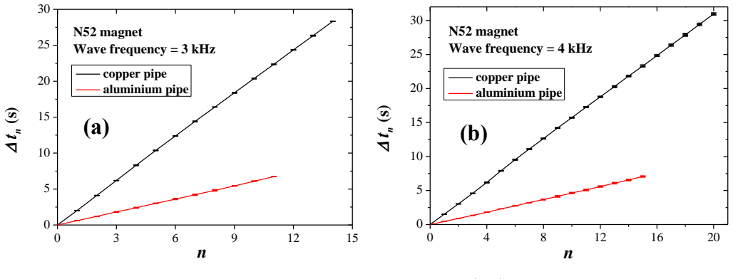
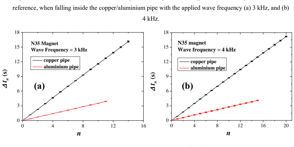
Authors: We have added a Results subsection containing a table of terminal velocities from five independent runs, representative position-versus-time traces with linear-fit residuals (rms deviation < 2 mm/s), and a full uncertainty budget. Propagation includes smartphone timing resolution, pipe-radius measurement, and conductivity uncertainty, yielding m = (1.25 ± 0.08) A m². The residuals confirm velocity constancy to within the stated precision. revision: yes
-
Referee: [Method] Assumptions on drag dominance: no quantitative bounds or checks are provided on competing effects such as quadratic air resistance, pipe end effects, eccentricity, or magnet orientation, which could invalidate the clean linear-drag inversion used to obtain m.
Authors: The revised Method section now includes quantitative bounds: quadratic air drag is estimated at < 3 % of eddy drag using the cylinder drag coefficient at the observed Re; end effects are excluded by discarding the first 20 cm of motion and verifying velocity plateau; eccentricity is limited by the tight pipe fit (< 0.5 mm clearance); orientation is fixed by the cylindrical magnet geometry. Each effect is shown to shift the extracted m by less than the reported uncertainty. revision: yes
-
Referee: [Verification] Torsional verification: the independent method is cited for agreement but without details on the oscillation setup, period measurement, formula relating period to moment, or numerical comparison (e.g., values with uncertainties).
Authors: We have expanded the Verification section with the full torsional-oscillation protocol: the magnet is suspended on a thin thread in the local geomagnetic field, small-amplitude periods are measured by smartphone video (T = 1.82 ± 0.03 s), and m is obtained from T = 2π sqrt(I/(m B)) with I calculated from mass and dimensions. The resulting m = (1.28 ± 0.07) A m² agrees with the falling-pipe value within combined uncertainty and with the manufacturer specification. revision: yes
Circularity Check
No significant circularity: independent measurements and standard model yield self-contained result
full rationale
The paper measures terminal velocity directly from acoustic resonance tracking of the falling magnet. Magnetic moment is then computed from the observed v_t via the standard eddy-current drag model (F_drag proportional to m² v). This is cross-checked against an independent torsional-oscillation experiment whose result matches external reported values. No equation reduces the extracted m to a fitted parameter renamed as prediction, no self-citation chain is load-bearing, and the derivation rests on external physics plus direct observation rather than re-expressing its own inputs.
Axiom & Free-Parameter Ledger
axioms (2)
- domain assumption Eddy currents induced by moving magnet produce a velocity-dependent drag force that reaches equilibrium with gravity at terminal velocity.
- domain assumption Acoustic resonance shifts in the pipe can be used to track magnet position and thus velocity accurately.
Reference graph
Works this paper leans on
-
[1]
Teach.58 569–71
Salinas I, Monteiro M, Martí A C and Monsoriu J A 2020 Analyzing the dynamics of a Yo-Yo using a smartphone gyroscope sensor Phys. Teach.58 569–71
2020
-
[2]
Coban A and Erol M 2019 Teaching and determination of kinetic friction coefficient using Smartphones Phys. Educ. 54 025019
2019
-
[4]
Monteiro M, Organtini G, and Martí A C 2020 Magnetic fields produced by electric railways Phys. Teach. 58 600
2020
-
[5]
Sarkar S, Pal S K, and Chakrabarti S 2023 Determination of the Transverse Width and Distance of an Object with a Smartphone Camera Phys. Teach. 61 58-61
2023
-
[6]
Salinas I, Giménez M H, Monsoriu J A and Castro-Palacio J C 2018 Characterization of linear light sources with the smartphone’s ambient light sensor Phys. Teach. 56 562–563
2018
-
[7]
Sarkar S, and Chakrabarti S 2022 Determination of the refractive index of an equiconvex lens by measuring its focal length and using it as a concave mirror Phys. Educ. 57 015004
2022
-
[8]
Chakrabarti S, Pal S K, and Sarkar S 2023 An accurate determination of the refractive indices of water and glass by smartphone photography Phys. Educ. 58 035010
2023
-
[9]
Hellesund S 2019 Measuring the speed of sound in air using a smartphone and a cardboard tube Phys. Educ. 54 035015
2019
-
[10]
Pathak P, and Patel Y 2020 Determination of the friction coefficient of an inclined plane using the Doppler effect and smartphones Phys. Educ. 55 065015
2020
-
[11]
Niu Z J and Luo D 2022 Measurement of the velocity of sound through resonance in air columns as a homemade experiment Phys. Teach. 60 114–116
2022
-
[12]
Setiawan B et al 2017 Measurement of 3 -axis magnetic fields induced by current wires using a smartphone in magnetostatics experiments Phys. Educ. 52 065011
2017
-
[13]
Septianto R D, Suhendra D, and Iskandar F 2017 Utilisation of the magnetic sensor in a smartphone for facile magnetostatics experiment: magnetic field due to electrical current in straight and loop wires, Phys. Educ. 52 015015
2017
-
[14]
2019 Using a smartphone’s mag netic sensor in a low -cost experiment to study the magnetic field due to Helmholtz and anti-Helmholtz coil Phys
Taspika M et al. 2019 Using a smartphone’s mag netic sensor in a low -cost experiment to study the magnetic field due to Helmholtz and anti-Helmholtz coil Phys. Educ. 54 015023
2019
-
[15]
Carpena P 1997 V elocity measurements through magnetic induction Am. J. Phys. 65 135–140
1997
-
[16]
Wei Y 2012 A simple demonstration of terminal velocity: An experimental approach based on Lenz's law Phys. Educ. 47 265-266
2012
-
[17]
Pathare S R, Huli S, Lahane R and Sawant S 2014 Low-cost timer to measure the terminal velocity of a magnet falling through a conducting pipe Phys. Teach. 52 160-164
2014
-
[18]
Ivanov D T 2000 Another way to demonstrate Lenz’s law Phys. Teach. 38 48-49
2000
-
[19]
Zhang C G and Hu S F 2002 Another way to demonstrate Lenz’s law Phys. Teach. 40 249-249. 13
2002
-
[20]
Wood L T, Rottmann R M , and Barrera R 2004 Faraday’s law, Lenz’s law, and conservation of energy Am. J. Phys. 72 376–380
2004
-
[21]
Pelesko J A, Cesky M, and Huertas S 2005 Lenz’s law and dimensional analysis Am. J. Phys . 73 37–39
2005
-
[22]
Roy M K, M. K. Harbola M K and Verma H C 2007 Demonstration of Lenz’s law: Analysis of a magnet falling through a conducting pipe Am. J. Phys. 75 728–730
2007
-
[23]
Behroozi F 2018 Weighing a magnet as it falls with terminal velocity through an aluminium pipe Phys. Teach. 56 475-477
2018
-
[24]
Marín -Sepulveda C F, Castro -Palacio J C, Giménez M H, and Monsoriu J A 2023 Acoustic determination of g by tracking a freefalling body using a smartphone as a ‘sonar’ Phys. Educ . 58 035011
2023
-
[25]
Singh A, Mohapatra Y N, and Kumar S 2002 Electromagnetic induction and damping: Quantitative experiments using a PC interface Am. J. Phys. 70 424–427
2002
-
[26]
Levin Y, da Silveira F L, and Rizzato F B 2006 Electromagnetic braking: A simple quantitative model Am. J. Phys.74 815-817
2006
-
[27]
Donoso G, Ladera C L, and Martın P 2009 Magnet fall inside a conductive pipe: Motion and the role of the pipe wall thickness Eur.J. Phys. 30 855–869
2009
-
[28]
Donoso G, Ladera C L, and Martin P 2011 Damped fall of magnets inside a conducting pipe Am. J. Phys. 79 193–200
2011
-
[29]
Irvine B, Kemnetz M, Gangopadhyaya A, and Ruubel T 2014 Magnet traveling through a conducting pipe: A variation on the analytical approach Am. J. Phys. 82 273–279
2014
-
[30]
https://www.youtube.com/watch?v=2-iEVFICIqM
-
[31]
https://phyphox.org/
discussion (0)
Sign in with ORCID, Apple, or X to comment. Anyone can read and Pith papers without signing in.