Recognition: unknown
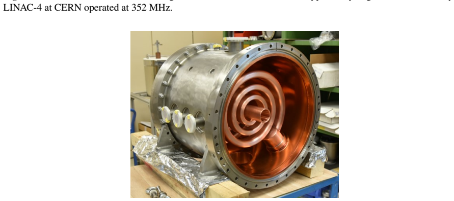
Low Beta, Normal Conducting Cavities
Pith reviewed 2026-05-08 16:09 UTC · model grok-4.3
The pith
Normal conducting cavities for non-relativistic beams require careful production steps from material choice through copper plating to reach reliable operation.
A machine-rendered reading of the paper's core claim, the machinery that carries it, and where it could break.
Core claim
Various types of normal conducting cavities are introduced with respect to their operation mode, application, advantages, and disadvantages. Special emphasis is placed on their production and the challenges from a finalized RF design up to the operating cavity, covering material choice, production methods, tolerances, alignment, cooling, and copper plating. The text closes with remarks on RF commissioning and conditioning.
What carries the argument
The production sequence for normal conducting low-beta cavities, especially the steps of material selection, precision machining, alignment, cooling integration, and copper plating.
If this is right
- Cavities finished with tight tolerances will preserve the designed electromagnetic fields and deliver the intended acceleration to non-relativistic beams.
- Effective cooling will permit sustained high-power operation without overheating or detuning.
- Uniform copper plating will keep surface resistance low and maintain good cavity quality factor during routine use.
- Precise alignment of assembled components will minimize beam steering and particle loss through the cavity chain.
Where Pith is reading between the lines
- These production practices could be adapted to guide fabrication of cavities for compact medical or industrial accelerators.
- Improved plating or alignment techniques might shorten the overall time from design to first beam in new facilities.
- The commissioning observations could inform hybrid normal-conducting plus superconducting layouts by highlighting interface issues.
Load-bearing premise
The review presumes that readers already understand basic RF cavity concepts and the distinction between normal-conducting and superconducting technologies.
What would settle it
A low-beta normal conducting cavity built according to the described production steps that nevertheless shows persistent field errors or high losses after standard commissioning would indicate that the listed challenges are incomplete.
Figures


read the original abstract
The contribution is on issues being especially related to normal conducting cavities operating at non-relativistic beam energies. Various types of cavities are introduced w.r.t. their operation mode, application, advantages, and disadvantages. Special emphasis is put on their production and the challenges along the way from finalized Rf-design up to the operating cavity. This covers the choice of material, production, tolerances, alignment, cooling, and the demanding task of copper plating. The contribution closes with some remarks on Rf-commissioning and -conditioning.
Editorial analysis
A structured set of objections, weighed in public.
Referee Report
Summary. The manuscript reviews practical issues in low-beta normal-conducting RF cavities for non-relativistic beams. It introduces cavity types by mode and application, noting advantages and disadvantages, then focuses on the production pipeline from finalized RF design through material selection, machining tolerances, alignment, cooling, copper plating, and finally RF commissioning and conditioning.
Significance. This descriptive review synthesizes established engineering challenges that are central to successful fabrication and operation of low-beta NC cavities in ion linacs and similar facilities. By compiling real-world constraints that often determine project timelines and performance, it serves as a useful reference for accelerator engineers and physicists, complementing purely theoretical design literature. No new quantitative claims, derivations, or experimental data are advanced.
minor comments (3)
- [Cavity types introduction] The overview of cavity types would benefit from a concise comparison table listing representative parameters (e.g., operating frequency, beta range, shunt impedance, and typical applications) to help readers quickly distinguish the modes discussed.
- [Production challenges] The copper-plating discussion could include one or two concrete recent examples (with references) of plating thickness tolerances or adhesion failures to make the 'demanding task' more tangible.
- [Throughout] A short glossary or footnote definitions for accelerator-specific terms (e.g., 'low beta', 'normal conducting' vs. superconducting) would address the assumption that readers already possess this background.
Simulated Author's Rebuttal
We thank the referee for the positive and accurate summary of our manuscript. The assessment correctly characterizes the contribution as a descriptive review of practical engineering challenges for low-beta normal-conducting cavities, without new quantitative claims. We appreciate the recommendation for minor revision.
Circularity Check
No significant circularity; purely descriptive review
full rationale
The manuscript is a review summarizing established practical challenges in fabricating and operating low-beta normal-conducting RF cavities (material selection, machining tolerances, alignment, cooling, copper plating, and RF conditioning). It introduces cavity types by mode and application but advances no new quantitative claim, derivation, or experimental result. There are no equations, predictions, fitted parameters, or self-citation chains that reduce any claim to its own inputs by construction. The contribution is self-contained against external benchmarks of accelerator engineering practice.
Axiom & Free-Parameter Ledger
axioms (1)
- standard math Standard electromagnetic theory and RF engineering principles govern cavity operation and design.
Reference graph
Works this paper leans on
-
[1]
Gerigk and M
Linac4 Technical Design Report, edited by F. Gerigk and M. Vretenar, CERN-AB-2006-084 ABP/RF, CERN, Geneva, Switzerland (2006)
2006
-
[2]
Ratzinger, The New GSI Pre-Stripper for High Current Heavy Ion Beams, Proc
U. Ratzinger, The New GSI Pre-Stripper for High Current Heavy Ion Beams, Proc. of the XVIII Linear Accel. Conf., TU202, Geneva, Switzerland (1996)
1996
-
[3]
Clemente, U
G. Clemente, U. Ratzinger, H. Podlech, L. Groening, R. Brodhage, and W. Barth, Development of room temperature crossbar-H-mode cavities for proton and ion acceleration in the low to medium beta range, Phys. Rev. Accel. & Beams 14, 110101 (2011)
2011
-
[4]
Wangler, RF Linear Accelerators, 2nd edition, pp
T.P. Wangler, RF Linear Accelerators, 2nd edition, pp. 232, Wiley-VCH, Weinheim, Ger- many (2008)
2008
-
[5]
Berkovits et al., Operational Experience and Future Goals of the SARAF Proton / Deuteron Linac, Proc
D. Berkovits et al., Operational Experience and Future Goals of the SARAF Proton / Deuteron Linac, Proc. of the XXVI Linear Accel. Conf., MO1A01, Tel Aviv, Israel (2012)
2012
-
[6]
Abbaslou and B
M. Abbaslou and B. Laxdal, Design Considerations for a Proton Linac for a Compact Accelerator Based Neutron Source, Proc. of the XXII Linear Accel. Conf., FR1AA05, Liverpool, UK (2022)
2022
-
[7]
https://bevatech.com/
-
[8]
Hähnel, A
H. Hähnel, A. Ate¸ s, U. Ratzinger, A 3D Printed IH-Type Linac Structure, Proc. of the HIAT Conf., TU1C4, Darmstadt, Germany (2022)
2022
-
[9]
Ramberger, priv
S. Ramberger, priv. communication
-
[10]
Groening, Analytic estimate of cooling of a cavity mantle and drift tube end plates, ALV2_note_20190218, GSI (2019)
L. Groening, Analytic estimate of cooling of a cavity mantle and drift tube end plates, ALV2_note_20190218, GSI (2019)
2019
-
[11]
CERN TE Technology Department, Copper Plated Discs on Nickel and Gold for GSI, CERN re- port (2023)
2023
-
[12]
Millar at al., High Power Conditioning and Breakdown Studies in Coupled Accelerating Struc- tures, Proc
L. Millar at al., High Power Conditioning and Breakdown Studies in Coupled Accelerating Struc- tures, Proc. of the 30th Linear Accel. Conf., TUPAB076, Liverpool, UK (2020). 16
2020
discussion (0)
Sign in with ORCID, Apple, or X to comment. Anyone can read and Pith papers without signing in.