Recognition: unknown
Input-Output Specifications and Dynamic Droop Coefficients: Stability and Performance Conditions for Grid-Forming IBRs
Pith reviewed 2026-05-08 15:55 UTC · model grok-4.3
The pith
Dynamic droop coefficients from input-output data yield scalable, unit-level stability conditions for grid-forming IBRs.
A machine-rendered reading of the paper's core claim, the machinery that carries it, and where it could break.
Core claim
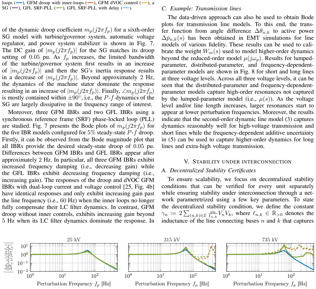
By defining dynamic droop coefficients that describe the small-signal dynamics of IBRs and SGs, the work shows that frequency stability conditions can be obtained from input-output data collected at the unit's point of interconnection. These coefficients, when paired with a lightweight dynamic transmission network model that accounts for line dynamics uncertainty, produce highly scalable stability criteria verifiable at the unit level given only a few key network parameters. The resulting specifications map to Bode-plot bounds for two broad classes of IBR responses, directly translating frequency control ancillary services into testable requirements and supplying insights for certifying grid
What carries the argument
The dynamic droop coefficient, which encodes the small-signal relationship between frequency and active power at the unit terminals and is extracted from input-output data to derive stability bounds.
Load-bearing premise
Input-output data collected at the point of interconnection fully captures the small-signal dynamics needed for stability, and the lightweight network model sufficiently accounts for line dynamics uncertainty.
What would settle it
A full-system simulation in which an IBR's measured dynamic droop coefficient satisfies the derived Bode-plot bounds yet the closed-loop system becomes unstable under the proposed network model, or the reverse case where the bounds are violated but stability holds.
Figures


read the original abstract
This paper proposes dynamic stability and performance conditions for grid-connected inverter-based resources (IBRs). To this end, we extend the notion of steady-state droop coefficients to dynamic droop coefficients to capture the small-signal dynamics of IBRs and synchronous generators (SGs). Notably, the dynamic droop coefficients can be obtained from input-output data collected at the unit's (e.g., IBR or SG) point of interconnection without requiring prior knowledge of IBR internals or controls structure. To obtain frequency stability conditions, this IBR model is combined with a lightweight dynamic transmission network model that accounts for uncertainty of line dynamics. The resulting stability conditions are highly scalable and, given a few key network parameters, can be verified at the unit level. To make the conditions practical and offer intuitive and illustrative interpretations, we map the frequency stability conditions to bounds on the Bode plot of the dynamic droop coefficient for two broad types of IBR responses. Moreover, our specifications on the dynamic droop coefficient (i) translate basic frequency control ancillary services into verifiable requirements, and (ii) provide insights into the much-debated question of how to certify an IBR as grid-forming (GFM). The results are illustrated using dynamic droop coefficients obtained using detailed simulations of GFM and GFL IBRs as well as SGs.
Editorial analysis
A structured set of objections, weighed in public.
Referee Report
Summary. The manuscript proposes dynamic stability and performance conditions for grid-connected inverter-based resources (IBRs) by extending steady-state droop coefficients to dynamic droop coefficients that capture small-signal dynamics of IBRs and synchronous generators (SGs). These coefficients are obtained from input-output data at the point of interconnection (POI) without requiring knowledge of internal controls. The IBR model is combined with a lightweight dynamic transmission network model that accounts for line dynamics uncertainty to derive scalable frequency stability conditions verifiable at the unit level using only a few key network parameters. The conditions are mapped to Bode-plot bounds for two broad types of IBR responses, translating ancillary service requirements into verifiable specifications and offering insights on certifying IBRs as grid-forming (GFM). Results are illustrated via simulations of GFM and GFL IBRs as well as SGs.
Significance. If the central claims hold, the work would be significant for providing a practical, data-driven pathway to stability certification and GFM classification that avoids detailed internal IBR models and full-system simulations. The scalability of unit-level verification and the explicit mapping of stability conditions to Bode bounds and ancillary services address real needs in high-IBR grids. The input-output extraction approach and simulation-based illustrations are strengths that enhance applicability for manufacturers and grid operators.
major comments (3)
- [Derivation of stability conditions using the lightweight network model] The section deriving the stability conditions from the lightweight dynamic transmission network model: the claim that this reduced-order model with uncertainty bounds on line dynamics is sufficient for unit-level verification to imply global small-signal stability requires explicit justification. It is unclear whether the abstraction preserves all relevant coupling modes (e.g., in meshed topologies or multi-IBR cases) or whether the uncertainty set is tight enough that local Bode-plot bounds on the dynamic droop coefficient guarantee stability of the full system; if higher-order dynamics or operating-point variations are omitted, the unit-level check could certify stability when the interconnected system is not.
- [Input-output data collection and dynamic droop coefficient extraction] The section on extraction of dynamic droop coefficients from POI input-output data: the assumption that measurements at the POI fully capture the closed-loop small-signal map without contamination from network feedback during data collection is load-bearing for the model-free claim. Without explicit excitation protocols, error bounds, or validation against detailed models showing that network effects are negligible or accounted for, the extracted coefficients may not reliably represent the unit's standalone dynamics for subsequent stability analysis.
- [Bode-plot bounds and ancillary service mapping] The section mapping stability conditions to Bode-plot bounds and ancillary services: while the translation to verifiable requirements for two IBR response types is conceptually useful, the paper must demonstrate (via the underlying transfer-function derivations) that the proposed bounds are both necessary and sufficient for the claimed frequency stability under the network uncertainty model; otherwise the practical certification insights for GFM IBRs rest on unverified equivalences.
minor comments (2)
- The abstract references simulations but provides no quantitative metrics (e.g., stability margins, error norms, or comparison to full-order models); adding such numbers would strengthen the illustration of the claims.
- Notation for the dynamic droop coefficient and its Bode representation should be introduced with a clear definition early in the manuscript to aid readability for readers outside the immediate subfield.
Simulated Author's Rebuttal
We thank the referee for their constructive and detailed feedback on our manuscript. The comments identify important areas for clarification and strengthening, particularly around the justification of the modeling assumptions and derivations. We address each major comment point-by-point below and indicate the revisions we will make in the next version of the manuscript.
read point-by-point responses
-
Referee: The section deriving the stability conditions from the lightweight dynamic transmission network model: the claim that this reduced-order model with uncertainty bounds on line dynamics is sufficient for unit-level verification to imply global small-signal stability requires explicit justification. It is unclear whether the abstraction preserves all relevant coupling modes (e.g., in meshed topologies or multi-IBR cases) or whether the uncertainty set is tight enough that local Bode-plot bounds on the dynamic droop coefficient guarantee stability of the full system; if higher-order dynamics or operating-point variations are omitted, the unit-level check could certify stability when the interconnected system is not.
Authors: We agree that the link between the lightweight network model and global stability requires more explicit justification. The model uses bounded uncertainty on line dynamics to derive conservative unit-level conditions via a robust small-gain argument applied to the interconnection at the POI. This is intended to ensure that satisfaction of the local Bode bounds implies stability of the full system under the modeled uncertainties, including equivalent representations for meshed networks. However, to address the concern directly, we will revise the derivation section to include a formal theorem statement with a proof outline, an expanded discussion of how the uncertainty set covers multi-IBR and meshed cases, and explicit acknowledgment of limitations regarding omitted higher-order dynamics or operating-point variations. revision: yes
-
Referee: The section on extraction of dynamic droop coefficients from POI input-output data: the assumption that measurements at the POI fully capture the closed-loop small-signal map without contamination from network feedback during data collection is load-bearing for the model-free claim. Without explicit excitation protocols, error bounds, or validation against detailed models showing that network effects are negligible or accounted for, the extracted coefficients may not reliably represent the unit's standalone dynamics for subsequent stability analysis.
Authors: This is a fair point regarding the practical applicability of the model-free extraction. The manuscript presents the dynamic droop coefficients as identifiable from POI measurements, with the implicit assumption that data collection can be performed under conditions where network feedback is either negligible (e.g., stiff grid or controlled test setup) or can be de-embedded. To strengthen this, we will add a new subsection detailing the excitation protocols used (including specific input signals and measurement considerations), quantitative error bounds on the identified coefficients, and validation comparisons against detailed internal IBR models to demonstrate when network contamination remains negligible. This will better support the claim that the extracted coefficients reliably represent standalone unit dynamics. revision: yes
-
Referee: The section mapping stability conditions to Bode-plot bounds and ancillary services: while the translation to verifiable requirements for two IBR response types is conceptually useful, the paper must demonstrate (via the underlying transfer-function derivations) that the proposed bounds are both necessary and sufficient for the claimed frequency stability under the network uncertainty model; otherwise the practical certification insights for GFM IBRs rest on unverified equivalences.
Authors: We acknowledge the need to make the necessity and sufficiency of the Bode bounds fully explicit through the derivations. In the paper, the bounds are obtained by substituting the dynamic droop coefficient into the closed-loop characteristic equation under the lightweight network model and applying frequency-domain stability criteria (e.g., Nyquist/Bode), yielding equivalent conditions for the two response types. To clarify this, we will expand the mapping section with additional step-by-step transfer-function algebra showing the direct equivalence between the stability inequalities and the proposed magnitude/phase bounds. This will also reinforce the ancillary service translations and GFM certification insights as direct consequences of the derived conditions. revision: yes
Circularity Check
No significant circularity: data-driven extraction and independent network model keep derivation self-contained
full rationale
The paper derives dynamic droop coefficients directly from external input-output measurements collected at the POI, without reference to internal IBR models or controls. These coefficients are then combined with a separate lightweight dynamic transmission network model (accounting for line dynamics uncertainty) to produce unit-level stability conditions. No step reduces a claimed prediction or stability bound to a fitted parameter by construction, nor does any load-bearing premise rely on self-citation chains or imported uniqueness theorems. The approach is explicitly measurement-based and externally verifiable using a few network parameters, rendering the derivation chain independent of its own outputs.
Axiom & Free-Parameter Ledger
axioms (2)
- domain assumption Small-signal linearization is valid for deriving frequency stability conditions
- domain assumption Lightweight dynamic transmission network model captures line dynamics uncertainty sufficiently for unit-level verification
Reference graph
Works this paper leans on
-
[1]
Global analysis of synchronization per- formance for power systems: Bridging the theory-practice gap,
F. Paganini and E. Mallada, “Global analysis of synchronization per- formance for power systems: Bridging the theory-practice gap,”IEEE Trans. Autom. Control, vol. 65, no. 7, pp. 3007–3022, 2020
2020
-
[2]
Grid-forming inverters: Are they the key for high renewable penetration?
J. Matevosyanet al., “Grid-forming inverters: Are they the key for high renewable penetration?”IEEE Power Energy Mag., vol. 17, no. 6, pp. 89–98, 2019
2019
-
[3]
Control of parallel connected inverters in standalone ac supply systems,
M. Chandorkar, D. Divan, and R. Adapa, “Control of parallel connected inverters in standalone ac supply systems,”IEEE Trans. Ind. Appl., vol. 29, no. 1, pp. 136–143, 1993
1993
-
[4]
A virtual synchronous machine implementation for distributed control of power converters in smartgrids,
S. D’Arco, J. A. Suul, and O. B. Fosso, “A virtual synchronous machine implementation for distributed control of power converters in smartgrids,”Electr. Pow. Sys. Res., vol. 122, pp. 180–197, 2015
2015
-
[5]
The effect of transmission-line dynamics on grid-forming dispatchable virtual os- cillator control,
D. Groß, M. Colombino, J.-S. Brouillon, and F. D ¨orfler, “The effect of transmission-line dynamics on grid-forming dispatchable virtual os- cillator control,”IEEE Trans. Control Netw. Syst., vol. 6, no. 3, pp. 1148–1160, 2019
2019
-
[6]
Conditions for stability of droop-controlled inverter-based microgrids,
J. Schiffer, R. Ortega, A. Astolfi, J. Raisch, and T. Sezi, “Conditions for stability of droop-controlled inverter-based microgrids,”Automatica, vol. 50, no. 10, pp. 2457–2469, 2014
2014
-
[7]
A lyapunov framework for nested dynamical systems on multiple time scales with application to converter-based power systems,
I. Suboti ´c, D. Groß, M. Colombino, and F. D ¨orfler, “A lyapunov framework for nested dynamical systems on multiple time scales with application to converter-based power systems,”IEEE Trans. Autom. Control, vol. 66, no. 12, pp. 5909–5924, 2021
2021
-
[8]
Control of low-inertia power systems,
F. D ¨orfler and D. Groß, “Control of low-inertia power systems,”Annual Review of Control, Robotics, and Autonomous Systems, vol. 6, no. 1, pp. 415–445, 2023
2023
-
[9]
Compensating network dynamics in grid-forming control,
D. Groß, “Compensating network dynamics in grid-forming control,” in Allerton Conference on Communication, Control, and Computing, 2022
2022
-
[10]
Principles of operation of grids of dc and ac subgrids interconnected by power converters,
O. Gomis-Bellmunt, E. S ´anchez-S´anchez, J. Ar ´evalo-Soler, and E. Prieto-Araujo, “Principles of operation of grids of dc and ac subgrids interconnected by power converters,”IEEE Trans. Power Del., vol. 36, no. 2, pp. 1107–1117, 2021
2021
-
[11]
Beyond low-inertia systems: Massive integration of grid- forming power converters in transmission grids,
A. Crivellaro, A. Tayyebi, C. Gavriluta, D. Groß, A. Anta, F. Kupzog, and F. D¨orfler, “Beyond low-inertia systems: Massive integration of grid- forming power converters in transmission grids,” inIEEE PES General Meeting, 2020
2020
-
[12]
Understanding small-signal stability of low-inertia systems,
U. Markovic, O. Stanojev, P. Aristidou, E. Vrettos, D. Callaway, and G. Hug, “Understanding small-signal stability of low-inertia systems,” IEEE Trans. Power Syst., vol. 36, no. 5, pp. 3997–4017, 2021
2021
-
[13]
Analysis of november 21, 2021, Kaua‘i island power system 18-20 hz oscillations,
S. Dong, B. Wang, J. Tan, C. J. Kruse, B. W. Rockwell, and A. Hoke, “Analysis of november 21, 2021, Kaua‘i island power system 18-20 hz oscillations,” 2023, arXiv:2301.05781
-
[14]
Effects of interaction of power converters coupled via power grid: A design-oriented study,
C. Wan, M. Huang, C. K. Tse, and X. Ruan, “Effects of interaction of power converters coupled via power grid: A design-oriented study,” IEEE Trans. Power Electron., vol. 30, no. 7, pp. 3589–3600, 2015
2015
-
[15]
Input-admittance cal- culation and shaping for controlled voltage-source converters,
L. Harnefors, M. Bongiorno, and S. Lundberg, “Input-admittance cal- culation and shaping for controlled voltage-source converters,”IEEE Trans. Ind. Electron., vol. 54, no. 6, pp. 3323–3334, 2007
2007
-
[16]
Impact of proportional resonant controller param- eters of VSC connected to AC grids with variable x/r characteristic on the small signal stability,
M. Haro-Larrode, M. Santos-Mugica, P. Eguia, R. Rodriguez-Sanchez, and A. Gil-de Muro, “Impact of proportional resonant controller param- eters of VSC connected to AC grids with variable x/r characteristic on the small signal stability,”International Journal of Electrical Power & Energy Systems, vol. 118, p. 105746, 2020
2020
-
[17]
An oscillatory stability criterion based on the unifieddq-frame impedance network model for power systems with high-penetration renewables,
H. Liu, X. Xie, and W. Liu, “An oscillatory stability criterion based on the unifieddq-frame impedance network model for power systems with high-penetration renewables,”IEEE Trans. Power Syst., vol. 33, no. 3, pp. 3472–3485, 2018
2018
-
[18]
Gain and phase: Decentralized stability conditions for power electronics-dominated power systems,
L. Huang, D. Wang, X. Wang, H. Xin, P. Ju, K. H. Johansson, and F. D¨orfler, “Gain and phase: Decentralized stability conditions for power electronics-dominated power systems,”IEEE Trans. Power Syst., vol. 39, no. 6, pp. 7240–7256, 2024
2024
-
[19]
Characterization of the grid- forming function of a power source based on its external frequency smoothing capability,
M.-S. Debry, G. Denis, and T. Prevost, “Characterization of the grid- forming function of a power source based on its external frequency smoothing capability,” inIEEE PowerTech, 2019
2019
-
[20]
Robust scale-free synthesis for frequency control in power systems,
R. Pates and E. Mallada, “Robust scale-free synthesis for frequency control in power systems,”IEEE Trans. Control Netw. Syst., vol. 6, no. 3, pp. 1174–1184, 2019
2019
-
[21]
Bullo,Lectures on Network Systems, 1st ed
F. Bullo,Lectures on Network Systems, 1st ed. Kindle Direct Publishing, 2024
2024
-
[22]
Overhead line parameters from handbook formulas and computer programs,
H. W. Dommel, “Overhead line parameters from handbook formulas and computer programs,”IEEE Trans. Power App. Syst., vol. PAS-104, no. 2, pp. 366–372, 1985. 11
1985
-
[23]
A universal model for accurate calculation of electromagnetic transients on overhead lines and underground cables,
A. Morched, B. Gustavsen, and M. Tartibi, “A universal model for accurate calculation of electromagnetic transients on overhead lines and underground cables,”IEEE Trans. Power Del., vol. 14, no. 3, pp. 1032– 1038, 1999
1999
-
[24]
Skogestad and I
S. Skogestad and I. Postlethwaite,Multivariable Feedback Control: Analysis and Design. Wiley, 2007
2007
-
[25]
Control of power converters in AC microgrids,
J. Rocabert, A. Luna, F. Blaabjerg, and P. Rodr ´ıguez, “Control of power converters in AC microgrids,”IEEE Trans. Power Electron., vol. 27, no. 11, pp. 4734–4749, 2012
2012
discussion (0)
Sign in with ORCID, Apple, or X to comment. Anyone can read and Pith papers without signing in.