Recognition: 2 theorem links
· Lean TheoremMultilayer model for coatings with arbitrary layers for superconducting radio-frequency applications
Pith reviewed 2026-05-11 02:51 UTC · model grok-4.3
The pith
The extended multilayer model for arbitrary layer sequences in superconducting RF coatings identifies the n=1 SIS structure as optimal while permitting sub-penetration-depth thicknesses with only minor losses.
A machine-rendered reading of the paper's core claim, the machinery that carries it, and where it could break.
Core claim
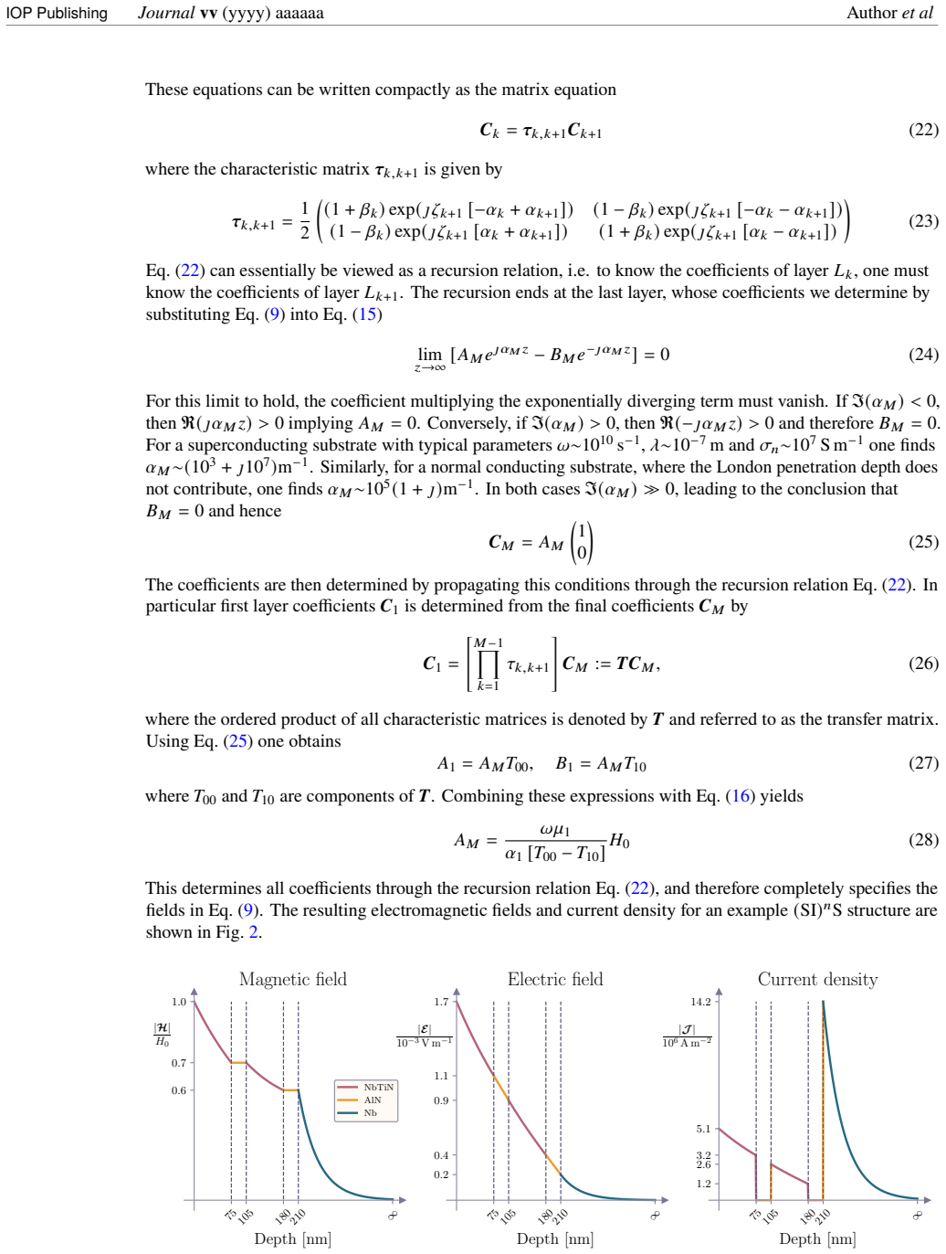
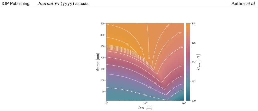
By extending the multilayer model to arbitrary layer types and full loss accounting, the analysis of (SI)^n S structures establishes that the n=1 configuration maximizes the applicable field, although the superconducting layers may be thinned below their penetration depth with only minor performance penalty; transition regions modeled by virtual layers with interpolated parameters degrade the maximum field and increase the effective penetration depth.
What carries the argument
The generalized multilayer model for arbitrary superconducting, normal-conducting, and insulating layers, using virtual-layer interpolation for interface transitions together with the Leontovich boundary condition and the Poynting theorem for loss separation.
If this is right
- Arbitrary combinations of superconducting, normal, and insulating layers can now be evaluated for RF performance.
- Superconducting layer thicknesses below the penetration depth remain usable with only small reduction in maximum field.
- Thicker transition zones in bilayers lower the maximum field and enlarge the effective penetration depth.
- Surface impedance from the Leontovich condition can be inserted directly into finite-element cavity simulations.
- Individual layer losses can be separated via the Poynting theorem to guide material choices.
Where Pith is reading between the lines
- Designers of SRF cavities could use the model to trade coating thickness against material cost while keeping accelerating gradients nearly constant.
- The virtual-layer approach suggests a route to include real interface roughness or interdiffusion in future simulations without new code.
- Inclusion of dielectric losses opens the possibility of modeling hybrid coatings that combine superconducting films with insulating barriers for thermal or field management.
Load-bearing premise
The virtual-layer interpolation for transition regions together with the complete set of loss terms yields quantitatively accurate predictions for real material interfaces without further experimental calibration.
What would settle it
Direct measurement of the maximum applicable RF field on fabricated (SI)^n S test samples for n=1 versus n=2, or comparison of computed versus measured surface impedance on a bilayer specimen with a controlled transition thickness.
Figures


read the original abstract
We extend the multilayer model of \etal{Kubo} for superconductor-insulator-superconductor (SIS) structures in two ways: first, by generalizing it to arbitrary sequences of layers of arbitrary type, i.e. superconducting, normal conducting, and insulating; and second, by accounting for all contributions, including ohmic losses and dielectric effects. We examine the maximum applicable field for $(\text{SI})^n\text{S}$ structures. We find that the optimum configuration corresponds to the $n=1$ case. However, the thickness of the superconducting coating layers can be reduced to below their penetration depth with minor performance penalty. We discuss the ability to model transitions in SS bilayers by introducing a set of virtual layers that represent the transition region through interpolated parameters. We find degradation of the maximum applicable field with thicker transition layers, and a larger effective penetration depth of the electromagnetic fields. Furthermore, the surface impedance of the multilayer structure is calculated using the Leontovich boundary condition, yielding a formulation suitable for integration into finite element simulations. Additionally, the Poynting theorem is used to determine the loss contributions of individual layers.
Editorial analysis
A structured set of objections, weighed in public.
Referee Report
Summary. The paper extends Kubo's multilayer model for SIS structures to arbitrary sequences of superconducting, normal-conducting, and insulating layers while including all ohmic and dielectric loss contributions. It computes the maximum applicable field for (SI)^n S coatings, reports that the n=1 configuration is optimal, and states that superconducting layer thicknesses can be reduced below the penetration depth with only minor performance penalty. Virtual layers with interpolated parameters are introduced to model transition regions in SS bilayers, leading to reported degradation of the maximum field and increased effective penetration depth for thicker transitions. Surface impedance is formulated via the Leontovich boundary condition for FEM use, and the Poynting theorem is applied to partition losses among layers.
Significance. If the numerical results hold, the generalization to arbitrary layer stacks and the explicit accounting for all loss mechanisms via the Poynting theorem provide a useful modeling tool for SRF coating design. The Leontovich-based surface-impedance expression suitable for finite-element integration and the loss-partitioning analysis are concrete strengths that could be adopted by the community. The n=1 optimality and sub-penetration-depth tolerance claims, if validated, would directly inform practical coating thickness choices.
major comments (1)
- [Discussion of virtual layers and numerical results for (SI)^n S structures] The headline claims that n=1 is optimal and that thicknesses below the penetration depth incur only minor penalty are obtained from the extended multilayer model that relies on virtual-layer interpolation for transition regions. No comparison to measured Rs(B) data or quench fields on calibrated SIS or SS bilayers is presented, so the quantitative accuracy of the 'minor penalty' statement remains an untested model output rather than a validated prediction.
minor comments (2)
- [Introduction / references] The abstract and text refer to 'Kubo et al.' without a full citation; the reference list should include the exact Kubo paper being extended.
- [Model formulation] Algebraic steps leading from the generalized boundary conditions to the maximum-field expressions are not shown; adding an appendix with the key derivations would improve reproducibility.
Simulated Author's Rebuttal
We thank the referee for the careful reading of our manuscript and for the constructive feedback. We appreciate the positive assessment of the model's potential utility for SRF coating design. Below we address the major comment directly and honestly.
read point-by-point responses
-
Referee: [Discussion of virtual layers and numerical results for (SI)^n S structures] The headline claims that n=1 is optimal and that thicknesses below the penetration depth incur only minor penalty are obtained from the extended multilayer model that relies on virtual-layer interpolation for transition regions. No comparison to measured Rs(B) data or quench fields on calibrated SIS or SS bilayers is presented, so the quantitative accuracy of the 'minor penalty' statement remains an untested model output rather than a validated prediction.
Authors: We agree that the reported optimality of the n=1 configuration and the assessment of minor performance penalty for sub-penetration-depth superconducting layers are numerical results obtained from the generalized multilayer model. The virtual-layer interpolation is explicitly introduced in the manuscript as a modeling technique to represent transition regions in SS bilayers via interpolated material parameters. The paper does not contain comparisons to measured Rs(B) data or quench fields on calibrated SIS or SS structures; its scope is the theoretical extension of Kubo's model, the inclusion of all loss channels via the Poynting theorem, and the derivation of a Leontovich-compatible surface impedance for FEM use. Kubo's original framework has been benchmarked against experiment in the prior literature, and our extensions retain the same underlying electrodynamics. We will revise the manuscript (partial revision) to add explicit statements in the abstract, introduction, and conclusions clarifying that these quantitative claims are model predictions under the stated assumptions, and to note that experimental validation of the 'minor penalty' result remains an important open task for the community. revision: partial
Circularity Check
No significant circularity in derivation chain
full rationale
The paper's results on n=1 optimum and sub-penetration-depth tolerance follow from direct numerical evaluation of the generalized multilayer model. This model is constructed from Maxwell equations, the Leontovich boundary condition, and the Poynting theorem applied to arbitrary user-specified layer sequences and parameters; virtual layers are introduced explicitly as an interpolation device for transition regions. No load-bearing step reduces by construction to a fitted input, self-definition, or self-citation chain. The cited Kubo model is external prior work, and all outputs remain independent of the target claims.
Axiom & Free-Parameter Ledger
free parameters (1)
- layer thicknesses and material parameters
axioms (2)
- standard math Electromagnetic fields obey Maxwell's equations inside each homogeneous layer
- domain assumption Leontovich boundary condition is valid at the cavity surface
invented entities (1)
-
virtual layers
no independent evidence
Lean theorems connected to this paper
-
IndisputableMonolith/Cost/FunctionalEquation.leanwashburn_uniqueness_aczel unclearWe extend the multilayer model of Kubo et al. ... by generalizing it to arbitrary sequences of layers ... accounting for all contributions, including ohmic losses and dielectric effects. ... B_max = min ...
-
IndisputableMonolith/Foundation/AbsoluteFloorClosure.leanabsolute_floor_iff_bare_distinguishability unclearthe transition layer is modeled as a sequence of virtual thin superconductors ... linear interpolation
Reference graph
Works this paper leans on
-
[1]
Superconducting properties of thin film Nb1-xTixN studied via the NMR of implanted 8Li
M. Asaduzzaman et al. “Superconducting properties of thin film Nb1-xTixN studied via the NMR of implanted 8Li”. In:Journal of Physics: Condensed Matter37.39 (Sept. 2025), p. 395701.issn: 1361-648X.doi:10.1088/1361-648x/ae0287.url: http://dx.doi.org/10.1088/1361-648X/ae0287
-
[2]
S. Calatroni. “20 Years of experience with the Nb/Cu technology for superconducting cavities and perspectives for future developments”. In:Physica C: Superconductivity441.1–2 (July 2006), pp. 95–101.issn: 0921-4534.doi:10.1016/j.physc.2006.03.044.url: http://dx.doi.org/10.1016/j.physc.2006.03.044
-
[3]
David.CRC handbook of chemistry and physics
R.L. David.CRC handbook of chemistry and physics. Internet Version 2005. Boca Raton, FL.: CRC press, 2005
work page 2005
-
[4]
Niboium-titanium nitride thin films for superconducting rf accelerator cavities
R. Di Leo et al. “Niboium-titanium nitride thin films for superconducting rf accelerator cavities”. In: Journal of Low Temperature Physics78.1–2 (Jan. 1990), pp. 41–50.issn: 1573-7357.doi: 10.1007/bf00682108.url:http://dx.doi.org/10.1007/BF00682108
work page doi:10.1007/bf00682108.url:http://dx.doi.org/10.1007/bf00682108 1990
-
[5]
D. Fonnesu et al. “Recipe optimization and SRF test of Cu-compatible Nb3Sn films by DC magnetron sputtering from a stoichiometric target”. In:Scientific Reports16.1 (Jan. 2026).issn: 2045-2322.doi: 10.1038/s41598-025-33547-w.url:http://dx.doi.org/10.1038/s41598-025-33547-w
work page doi:10.1038/s41598-025-33547-w.url:http://dx.doi.org/10.1038/s41598-025-33547-w 2026
-
[6]
I. Gonz ´alez D´ıaz-Palacio et al. “Thermal annealing of superconducting niobium titanium nitride thin films deposited by plasma-enhanced atomic layer deposition”. In:Journal of Applied Physics134.3 (July 2023).issn: 1089-7550.doi:10.1063/5.0155557.url: http://dx.doi.org/10.1063/5.0155557
-
[7]
Enhancement of rf breakdown field of superconductors by multilayer coating
A. Gurevich. “Enhancement of rf breakdown field of superconductors by multilayer coating”. In: Applied Physics Letters88.1 (Jan. 2006).issn: 1077-3118.doi:10.1063/1.2162264.url: http://dx.doi.org/10.1063/1.2162264. 10 IOP PublishingJournalvv(yyyy) aaaaaa Authoret al
-
[8]
Microwave response of superconductors that obey local electrodynamics
F. Herman and R. Hlubina. “Microwave response of superconductors that obey local electrodynamics”. In:Physical Review B104.9 (Sept. 2021).issn: 2469-9969.doi:10.1103/physrevb.104.094519. url:http://dx.doi.org/10.1103/PhysRevB.104.094519
-
[9]
Jackson.Classical Electrodynamics
J.D. Jackson.Classical Electrodynamics. 3rd ed. New York: Wiley, 1999.isbn: 978-0471309321
work page 1999
-
[10]
Critical fields of SRF materials
T. Junginger et al. “Critical fields of SRF materials”. en. In:Proceedings of the 9th Int. Particle Accelerator Conf.IPAC2018 (2018), Canada.doi:10.18429/JACOW-IPAC2018-THPAL118.url: http://jacow.org/ipac2018/doi/JACoW-IPAC2018-THPAL118.html
-
[11]
T. Kubo. “Multilayer coating for higher accelerating fields in superconducting radio-frequency cavities: a review of theoretical aspects”. In:Superconductor Science and Technology30.2 (Dec. 2016), p. 023001.issn: 1361-6668.doi:10.1088/1361-6668/30/2/023001.url: http://dx.doi.org/10.1088/1361-6668/30/2/023001
-
[12]
RF field-attenuation formulae for the multilayer coating model
T. Kubo, Y. Iwashita, and T. Saeki. “RF field-attenuation formulae for the multilayer coating model”. In: Proceedings of the 4th International Particle Accelerator Conference (IPAC 2013). Shangai, China, 2013, pp. 2343–2345.isbn: 978-3095450-122-9
work page 2013
-
[13]
Radio-frequency electromagnetic field and vortex penetration in multilayered superconductors
T. Kubo, Yoshihisa Iwashita, and Takayuki Saeki. “Radio-frequency electromagnetic field and vortex penetration in multilayered superconductors”. In:Applied Physics Letters104.3 (Jan. 2014).issn: 1077-3118.doi:10.1063/1.4862892.url:http://dx.doi.org/10.1063/1.4862892
work page doi:10.1063/1.4862892.url:http://dx.doi.org/10.1063/1.4862892 2014
-
[14]
Landau and E.M Lifshitz.Electrodynamics of continuous media
L.D. Landau and E.M Lifshitz.Electrodynamics of continuous media. Oxford, England: Pergamon Press, 1960
work page 1960
-
[15]
The high-frequency resistance of superconducting tin
H. London. “The high-frequency resistance of superconducting tin”. In:Proceedings of the Royal Society of London. Series A. Mathematical and Physical Sciences176.967 (Nov. 1940), pp. 522–533. issn: 2053-9169.doi:10.1098/rspa.1940.0105.url: http://dx.doi.org/10.1098/rspa.1940.0105
-
[16]
Theory of the anomalous skin effect in normal and superconducting metals
D. C. Mattis and J. Bardeen. “Theory of the anomalous skin effect in normal and superconducting metals”. In:Physical Review111.2 (July 1958), pp. 412–417.issn: 0031-899X.doi: 10.1103/physrev.111.412.url:http://dx.doi.org/10.1103/PhysRev.111.412
work page doi:10.1103/physrev.111.412.url:http://dx.doi.org/10.1103/physrev.111.412 1958
-
[17]
Superconducting penetration depth of niobium
B. W. Maxfield and W. L. McLean. “Superconducting penetration depth of niobium”. In:Physical Review139.5A (Aug. 1965), A1515–A1522.issn: 0031-899X.doi:10.1103/physrev.139.a1515. url:http://dx.doi.org/10.1103/PhysRev.139.A1515
-
[18]
K. Mitzner. “Effective boundary conditions for reflection and transmission by an absorbing shell of arbitrary shape”. In:IEEE Transactions on Antennas and Propagation16.6 (Nov. 1968), pp. 706–712. issn: 0096-1973.doi:10.1109/tap.1968.1139283.url: http://dx.doi.org/10.1109/TAP.1968.1139283
-
[19]
Theory of electromagnetic properties of superconducting and normal systems. I
S.B. Nam. “Theory of electromagnetic properties of superconducting and normal systems. I”. In: Physical Review156.2 (Apr. 1967), pp. 470–486.issn: 0031-899X.doi: 10.1103/physrev.156.470. url:http://dx.doi.org/10.1103/PhysRev.156.470
-
[20]
Padamsee.RF superconductivity, science, technology and applications
H. Padamsee.RF superconductivity, science, technology and applications. New York, NY: John Wiley & Sons, Apr. 2009.isbn: 978-3-527-40572-5
work page 2009
-
[21]
S. Posen et al. “Advances in Nb3Sn superconducting radiofrequency cavities towards first practical accelerator applications”. In:Superconductor Science and Technology34.2 (Jan. 2021), p. 025007.issn: 1361-6668.doi:10.1088/1361-6668/abc7f7.url: http://dx.doi.org/10.1088/1361-6668/abc7f7
-
[22]
Fabrication of superconducting Nb3Sn film by Co-sputtering
N. Sayeed et al. “Fabrication of superconducting Nb3Sn film by Co-sputtering”. In:Vacuum212 (June 2023), p. 112019.issn: 0042-207X.doi:10.1016/j.vacuum.2023.112019.url: http://dx.doi.org/10.1016/j.vacuum.2023.112019
-
[23]
Tinkham.Introduction to superconductivity
M. Tinkham.Introduction to superconductivity. 2nd ed. New York, NY: McGraw-Hill, Nov. 1995.isbn: 978-0-070-64878-4
work page 1995
-
[24]
Superconducting RF materials other than bulk niobium: a review
A.-M. Valente-Feliciano. “Superconducting RF materials other than bulk niobium: a review”. In: Superconductor Science and Technology29.11 (Sept. 2016), p. 113002.issn: 1361-6668.doi: 10.1088/0953-2048/29/11/113002.url: http://dx.doi.org/10.1088/0953-2048/29/11/113002
-
[25]
Development of the superconducting rf 2-cell cavity for cERL injector at KEK
K. Watanabe et al. “Development of the superconducting rf 2-cell cavity for cERL injector at KEK”. In: Nuclear Instruments and Methods in Physics Research Section A: Accelerators, Spectrometers, Detectors and Associated Equipment714 (June 2013), pp. 67–82.issn: 0168-9002.doi: 10.1016/j.nima.2013.02.035.url:http://dx.doi.org/10.1016/j.nima.2013.02.035. 11 ...
work page doi:10.1016/j.nima.2013.02.035.url:http://dx.doi.org/10.1016/j.nima.2013.02.035 2013
-
[26]
Low temperature aluminum nitride thin films for sensory applications
E. Yarar et al. “Low temperature aluminum nitride thin films for sensory applications”. In:AIP Advances6.7 (July 2016).issn: 2158-3226.doi:10.1063/1.4959895.url: http://dx.doi.org/10.1063/1.4959895
-
[27]
S.V. Yuferev and N. Ida.Surface impedance boundary conditions: a comprehensive approach. CRC press, 2018.doi:10.1201/9781315219929. 12
discussion (0)
Sign in with ORCID, Apple, or X to comment. Anyone can read and Pith papers without signing in.