Recognition: unknown
A shifted interface approach for internal discontinuities in poroelastic media
Pith reviewed 2026-05-10 09:10 UTC · model grok-4.3
The pith
The shifted interface method can be adapted to transient poroelasticity to model embedded cracks on non-body-fitted meshes.
A machine-rendered reading of the paper's core claim, the machinery that carries it, and where it could break.
Core claim
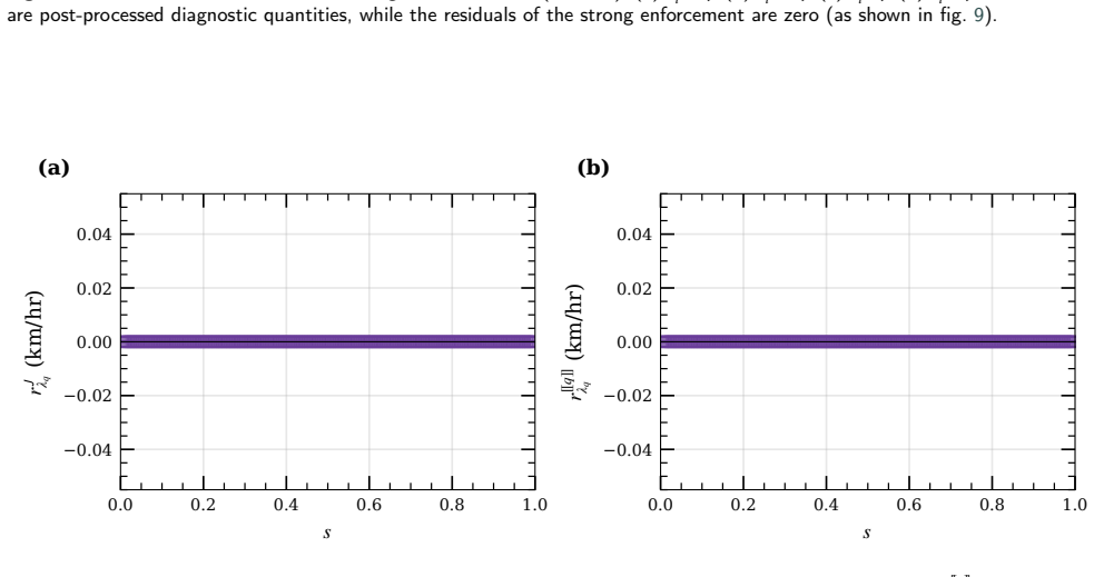
A unified derivation yields shifted forms for hydraulic transmission and mechanical traction coupling in transient poroelasticity. The true crack is replaced by a surrogate approximation where interface conditions are transferred through local expansions. Two enforcement strategies, weak integral and strong pointwise, are compared. Numerical experiments on offset mesh-aligned, boundary-intersecting angled, embedded angled, and multi-crack configurations show that interface residuals converge as O(h) away from crack tips, with first-order rates recovered when a small tip region is excluded.
What carries the argument
Shifted interface method using local expansions to transfer both hydraulic and mechanical interface conditions from true discontinuities to surrogate interfaces.
Load-bearing premise
Local expansions remain accurate for transferring coupled hydraulic and mechanical interface conditions near crack tips and in transient regimes.
What would settle it
Numerical results from an embedded angled crack test showing interface residuals that fail to converge at O(h) even after excluding a small region around the tip would indicate the claim does not hold.
Figures


read the original abstract
Porous media containing cracks, fractures, or internal discontinuities arise throughout subsurface geomechanics, biomechanics, and materials science. Numerical simulation of the coupled hydromechanical response is inherently challenging because the pressure and displacement fields are tightly coupled through the Biot equations, requiring stable mixed formulations. These difficulties are compounded when cracks are present, because standard mesh-conforming approaches require costly, labor-intensive, body-fitted meshing, while unfitted methods often require cut-cell integration, enrichment functions, or additional stabilization. In this work, we use an alternative approach, we adapt the shifted interface method to coupled transient poroelasticity with embedded interfaces. The method replaces the true crack by a surrogate approximation where interface conditions are transferred through local expansions. A unified derivation yields shifted forms for both hydraulic transmission and mechanical traction coupling. Two enforcement strategies are extensively compared: a weak (integral) enforcement and a strong (pointwise) enforcement. Four test cases of increasing geometric complexity (offset mesh-aligned, boundary-intersecting angled, embedded angled, and multi-crack configurations) validate the formulation. Away from crack tips, interface residuals converge as O(h); near tips, localized post-processing artifacts degrade the global rate, but first-order convergence is recovered when a small tip region is excluded. A multi-crack demonstration with four simultaneously embedded cracks of distinct geometry and interface properties confirms the practical applicability of the framework. These results support the shifted interface method as a practical framework for poroelastic crack modeling on non-body-fitted meshes with geometrically complex embedded interfaces.
Editorial analysis
A structured set of objections, weighed in public.
Referee Report
Summary. The manuscript adapts the shifted interface method to transient poroelasticity with embedded discontinuities. It replaces true cracks with surrogate interfaces, derives unified shifted forms for hydraulic (pressure/flux) and mechanical (traction/displacement) transmission conditions via local expansions, and compares weak integral versus strong pointwise enforcement. Validation on four test cases of increasing complexity (offset mesh-aligned, boundary-intersecting angled, embedded angled, and multi-crack) shows interface residuals converging as O(h) away from crack tips, with first-order rates recovered when tip regions are excluded. A multi-crack demonstration with distinct geometries and properties supports applicability to complex embedded interfaces on non-body-fitted meshes.
Significance. If the local expansions remain accurate for the coupled Biot system, the work supplies a practical alternative to body-fitted meshing or enrichment techniques for poroelastic crack problems in geomechanics and biomechanics. Strengths include the unified derivation for both flow and mechanics, direct comparison of enforcement strategies, manufactured-solution validation across geometrically varied cases, and explicit acknowledgment of tip-region degradation with recovery upon exclusion. These elements position the framework as mesh-flexible for complex discontinuities.
major comments (1)
- Abstract: The reported O(h) convergence of interface residuals is measured away from crack tips, with first-order rates recovered only after excluding a small tip region. For the tightly coupled Biot system, where displacement and pressure gradients are singular at tips and linked through storage and Darcy terms, the local expansions used to transfer the true jump conditions to the surrogate interface may introduce non-uniform errors when the distance to the tip is O(h). Additional analysis or tests (e.g., transient loading with quantified residuals inside the singular zone) are needed to confirm consistency of the transferred conditions, as this directly supports the central claim of a practical framework for poroelastic crack modeling.
minor comments (2)
- The abstract and results section would benefit from explicit statement of the Taylor expansion order employed in the local expansions for both hydraulic and mechanical conditions.
- Include quantitative error tables (with exact rates and L2/H1 norms) for the four test cases alongside convergence plots to permit direct assessment of the claimed O(h) behavior away from tips.
Simulated Author's Rebuttal
We thank the referee for the positive assessment of the manuscript and the recommendation for minor revision. We provide a detailed response to the major comment below.
read point-by-point responses
-
Referee: Abstract: The reported O(h) convergence of interface residuals is measured away from crack tips, with first-order rates recovered only after excluding a small tip region. For the tightly coupled Biot system, where displacement and pressure gradients are singular at tips and linked through storage and Darcy terms, the local expansions used to transfer the true jump conditions to the surrogate interface may introduce non-uniform errors when the distance to the tip is O(h). Additional analysis or tests (e.g., transient loading with quantified residuals inside the singular zone) are needed to confirm consistency of the transferred conditions, as this directly supports the central claim of a practical framework for poroelastic crack modeling.
Authors: We thank the referee for this insightful comment on the behavior near crack tips. The manuscript already reports that interface residuals converge as O(h) away from crack tips, with first-order rates recovered upon exclusion of a small tip region; this is explicitly stated in the abstract and demonstrated across the four test cases. The local expansions rely on Taylor series that assume local smoothness, and their accuracy necessarily degrades within O(h) of the tip because the Biot solution fields (displacements and pressures) are singular there due to the storage and Darcy coupling terms. This singularity is a physical feature of the problem and would affect the local accuracy of any unfitted or body-fitted discretization that does not employ dedicated tip enrichment. The consistency of the shifted transmission conditions is confirmed by the clean O(h) convergence obtained on the smooth portions of the interfaces in all geometries considered, including configurations with transient poroelastic loading. We therefore view the existing validation as sufficient to support the central claim of a practical framework for embedded discontinuities on unfitted meshes. No additional tests inside the singular zone are required, as they would simply reproduce the expected degradation already documented. revision: no
Circularity Check
Derivation is self-contained from Biot equations with no circular reductions
full rationale
The paper presents a unified derivation of shifted hydraulic and mechanical interface conditions directly from the Biot poroelastic equations and standard transmission conditions at discontinuities, using local Taylor expansions to transfer jumps to a surrogate interface. Validation relies on manufactured solutions and convergence studies rather than parameter fitting to target outputs. No self-definitional loops, fitted inputs renamed as predictions, or load-bearing self-citations that collapse the central claim to its own inputs are present in the provided derivation chain. The adaptation of the shifted interface method supplies an independent starting point whose extension to transient coupled poroelasticity is explicitly constructed from first principles.
Axiom & Free-Parameter Ledger
axioms (2)
- domain assumption Linear Biot theory governs the coupled hydromechanical response in the porous medium.
- ad hoc to paper Local expansions around the surrogate interface accurately transmit the true crack conditions for both flow and traction.
Reference graph
Works this paper leans on
-
[1]
Computer Methods in Applied Mechanics and Engineering 351, 253–280
Ager,C.,Schott,B.,Winter,M.,Wall,W.A.,2019.Anitsche-basedcutfiniteelementmethodforthecouplingofincompressiblefluidflowwithporoelasticity. Computer Methods in Applied Mechanics and Engineering 351, 253–280. Arnold, D.N., Brezzi, F., Fortin, M.,
2019
-
[2]
Mathematics of Computation 90, 2041–2069
Analysis of the shifted boundary method for the poisson problem in domains with corners. Mathematics of Computation 90, 2041–2069. Atallah, N.M., Canuto, C., Scovazzi, G.,
2041
-
[3]
Computer Methods in Applied Mechanics and Engineering 394, 114885
The high-order shifted boundary method and its analysis. Computer Methods in Applied Mechanics and Engineering 394, 114885. doi:10.1016/j.cma.2022.114885. Ateshian, G.A.,
-
[4]
Fault zone hydrogeology. Earth-Science Reviews 127, 171–192. doi:10.1016/j. earscirev.2013.09.008. Berre,I.,Radu,F.A.,Nordbotten,J.M.,etal.,2019. Flowinfracturedporousmedia:Areviewofconceptualmodelsanddiscretizationapproaches. Transport in Porous Media 130, 215–236. doi:10.1007/s11242-018-1171-6. Berre, N., Mardal, K.A., Massing, A., Yotov, I.,
work page doi:10.1016/j 2013
-
[5]
arXiv preprint arXiv:2512.17521
A cut finite element method for the biot system of poroelasticity. arXiv preprint arXiv:2512.17521 . Bouklas, N., Landis, C.M., Huang, R.,
-
[6]
Comptes Rendus Mathematique 348, 1217–1220
Ghost penalty. Comptes Rendus Mathematique 348, 1217–1220. doi:10.1016/j.crma.2010.10.006. Burman, E., Hansbo, P., Larson, M.G., et al.,
-
[7]
Cutfem: Discretizing geometry and partial differential equations. International Journal for Numerical Methods in Engineering 104, 472–501. doi:10.1002/nme.4823. Caine, J.S., Evans, J.P., Forster, C.B.,
-
[8]
Fault zone architecture and permeability structure. Geology 24, 1025–1028. doi:10.1130/0091-7613(1996) 024<1025:FZAAPS>2.3.CO;2. Chambat, F., Benzoni-Gavage, S., Ricard, Y.,
-
[9]
Computer Methods in Applied Mechanics and Engineering 347, 957–982
Springer. Chukwudozie,C.,Bourdin,B.,Yoshioka,K.,2019. Avariationalphase-fieldmodelforhydraulicfracturinginporousmedia. ComputerMethodsinApplied Mechanics and Engineering 347, 957–982. doi:10.1016/j.cma.2018.12.037. Costabel, M., Dauge, M.,
-
[10]
Journal of biomechanics 32, 217–238
Bone poroelasticity. Journal of biomechanics 32, 217–238. Dauge,M.,2008. Regularityandsingularitiesinpolyhedraldomains. Lecture,Karlsruhe,April2008. Availableathttps://perso.univ-rennes1.fr/monique. dauge/publis/TalkKarlsruhe08.pdf. Demlow, A.,
2008
-
[11]
SEMA SIMAI Springer Series 6, 47–76
A review of the XFEM-based approximation of flow in fractured porous media. SEMA SIMAI Springer Series 6, 47–76. doi:10.1007/978-3-319-41246-7_3. Foulger, G.R., Wilson, M.P., Gluyas, J.G., Julian, B.R., Davies, R.J.,
-
[12]
Earth-Science Reviews 178, 438–514
Global review of human-induced earthquakes. Earth-Science Reviews 178, 438–514. Grisvard,P.,2011.EllipticProblemsinNonsmoothDomains.volume69ofClassicsinAppliedMathematics.SocietyforIndustrialandAppliedMathematics (SIAM), Philadelphia, PA. Reprint of the 1985 original. Gustafsson, T., McBain, G.D.,
2011
-
[13]
URL: https://doi.org/10.21105/joss.02369, doi:10.21105/joss.02369. Hansbo,A.,Hansbo,P.,2002. Anunfittedfiniteelementmethod,basedonnitsche’smethod,forellipticinterfaceproblems. ComputerMethodsinApplied Mechanics and Engineering 191, 5537–5552. doi:10.1016/S0045-7825(02)00524-8. Huber,M.L.,Perkins,R.A.,Laesecke,A.,Friend,D.G.,Sengers,J.V.,Assael,M.J.,Metaxa...
-
[14]
Earth System Science Data 15, 3163–3182
Global physics-based database of injection-induced seismicity. Earth System Science Data 15, 3163–3182. Li,K.,Atallah,N.M.,Main,G.A.,Scovazzi,G.,2020. Theshiftedinterfacemethod:Aflexibleapproachtoembeddedinterfacecomputations. International Journal for Numerical Methods in Engineering 121, 492–518. doi:10.1002/nme.6231. Li, K., Gorgi, A., Rossi, R., Scovazzi, G.,
-
[15]
part i: Poisson and stokes problems
The shifted boundary method for embedded domain computations. part i: Poisson and stokes problems. Journal of Computational Physics 372, 972–995. doi:10.1016/j.jcp.2017.10.026. Mikelić, A., Wheeler, M.F., Wick, T.,
-
[16]
Computational Geosciences 19, 1171–1195
Phase-field modeling of a fluid-driven fracture in a poroelastic medium. Computational Geosciences 19, 1171–1195. doi:10.1007/s10596-015-9532-5. Moës, N., Dolbow, J., Belytschko, T.,
-
[17]
Journal of Computational Physics , 114615
The tempered finite element method. Journal of Computational Physics , 114615. Riley, D., 2025.solve_nivp: Adaptive time integration for nonlinear initial-value problems.https://github.com/driley8/solve_nivp. Python package. Rivière, B.,
2025
-
[18]
volume 35 ofFrontiers in Applied Mathematics
Discontinuous Galerkin Methods for Solving Elliptic and Parabolic Equations: Theory and Implementation. volume 35 ofFrontiers in Applied Mathematics. SIAM, Philadelphia. doi:10.1137/1.9780898717440. Rodrigo, C., Gaspar, F., Hu, X., Zikatanov, L.,
-
[19]
Journal of Computational Physics 372, 996–1026
Linear advection–diffusion and incompressible navier–stokes equations. Journal of Computational Physics 372, 996–1026. doi:10.1016/j.jcp.2018.01.023. Starnoni, M., Berre, I., Keilegavlen, E., Nordbotten, J.M.,
-
[20]
International Journal of Rock Mechanics and Mining Sciences 42, 109–125
Geohydromechanical processes in the excavation damaged zone in crystalline rock, rock salt, and indurated and plastic clays—in the context of radioactive waste disposal. International Journal of Rock Mechanics and Mining Sciences 42, 109–125. Ulm,F.J.,Constantinides,G.,Heukamp,F.H.,2004. Isconcreteaporomechanicsmaterials?—amultiscaleinvestigationofporoela...
2004
-
[21]
Advances in Computational Mathematics , author =
Piecewise polynomial, positive definite and compactly supported radial functions of minimal degree. Advances in Computational Mathematics 4, 389–396. doi:10.1007/BF02123482. Wilson, Z.A., Landis, C.M.,
-
[22]
Journal of the Mechanics and Physics of Solids 96, 264–290
Phase-field modeling of hydraulic fracture. Journal of the Mechanics and Physics of Solids 96, 264–290. doi:10.1016/ j.jmps.2016.07.019. Zemlyanova,A.Y.,Mogilevskaya,S.G.,Schillinger,D.,2023. Numericalsolutionofthetwo-dimensionalsteigmann–ogdenmodelofmaterialsurfacewith a boundary. Physica D: Nonlinear Phenomena 443, 133531. Zorrilla,R.,Rossi,R.,Scovazzi,...
2016
discussion (0)
Sign in with ORCID, Apple, or X to comment. Anyone can read and Pith papers without signing in.