Recognition: unknown
Scattering-Matrix-Based Parametric Characterization of a Two-Port Bridged-T Network for Microstrip Filter Applications
Pith reviewed 2026-05-10 02:58 UTC · model grok-4.3
The pith
The bridged-T network acts as a high-pass filter when its two inductors are set equal, because this cancels all even coefficients in the numerator of the S11 transfer function.
A machine-rendered reading of the paper's core claim, the machinery that carries it, and where it could break.
Core claim
The central claim is that a bridged-T network whose inductors L1 and L2 are identical yields an S11 transfer function whose numerator contains only odd powers of normalized frequency. This symmetry property converts the network into a high-pass filter whose scattering parameters can be calculated directly from the T-to-S conversion and whose simulated response at 1 GHz shows the expected sharp roll-off.
What carries the argument
The numerator polynomial of the S11 transfer function obtained after T-to-S matrix conversion; the equality L1 = L2 removes every even-powered coefficient from that polynomial.
If this is right
- The bridged-T topology can be used directly for microstrip high-pass filters once L1 is set equal to L2.
- The magnitude and phase of both S11 and S21 can be computed parametrically after frequency normalization.
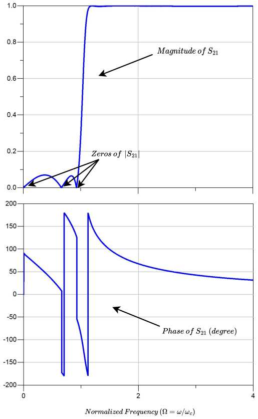
- Roll-off rates of approximately -30 dB/GHz for S11 and -32 dB/GHz for S21 are obtained at a 1 GHz corner frequency.
Where Pith is reading between the lines
- The same symmetry cancellation may appear in other bridged or lattice networks if corresponding element values are made equal.
- At frequencies well above 1 GHz the ideal lumped-element assumption will fail and full-wave simulation will be required to retain the odd-only property.
- The closed-form S-parameter expressions allow rapid tuning of the corner frequency by scaling the common inductor value while keeping the ratio of other elements fixed.
Load-bearing premise
The derivations and simulations treat all circuit elements as ideal lumped components with no parasitic reactance or distributed-line effects at 1 GHz.
What would settle it
Fabricate the bridged-T circuit with equal inductors, measure the actual S11 response versus frequency, and check whether even-powered terms appear in the extracted numerator polynomial.
Figures


read the original abstract
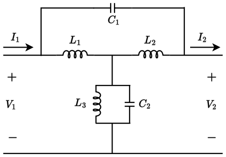
The purpose of this study is to characterize a two-port Bridged-T network using transmission (T) and scattering (S) matrices. Using mathematical derivations, scattering parameters including S11, S12, S21, and S22 have been derived from the T and S matrices to permit a detailed investigation of the network's performance. As two of the most relevant parameters in the design of microstrip filters, both the magnitude and phase of S11 and S21 have been parametrically calculated after normalizing the frequency. Furthermore, when the inductors L1 and L2 are identical, all even coefficients of the numerator polynomial in the S11 transfer function are eliminated, leaving only the odd coefficients behind. Based on this feature, the bridged-T circuit is designed to operate as a high-pass filter. Therefore, the magnitude and phase of both S11 and S21 have been simulated for the designed filter with a corner frequency of 1 GHz. Simulation results performed by Keysight ADS show that S11 and S21 for the high-pass filter built upon the bridged-T network have sharp roll-off ratios of -30dB/GHz and -32dB/GHz respectively.
Editorial analysis
A structured set of objections, weighed in public.
Referee Report
Summary. The manuscript derives the scattering parameters (S11, S12, S21, S22) of a two-port bridged-T network from its transmission (T) matrix using standard T-to-S conversion formulas. It parametrically examines the magnitude and phase of S11 and S21 after frequency normalization and shows that equating the two series inductors L1 = L2 eliminates all even-powered coefficients in the numerator polynomial of the S11 transfer function. This algebraic property is exploited to realize a high-pass filter with a 1 GHz corner frequency, whose simulated S-parameters in Keysight ADS exhibit roll-off rates of -30 dB/GHz for S11 and -32 dB/GHz for S21.
Significance. If the lumped-element assumptions hold for the intended microstrip realization, the work supplies closed-form S-parameter expressions and a parameter-free design rule (inductor equality) that directly yields a high-pass response with sharp roll-off, offering a compact algebraic route to filter synthesis that could be useful for microstrip applications.
major comments (2)
- [Derivation of S-parameters and high-pass filter design] The derivation of the S-parameters and the subsequent claim of a sharp high-pass roll-off rest on the assumption that the bridged-T network is exactly representable by ideal lumped inductors and capacitors whose T-matrix converts directly to S-parameters. At the stated design frequency of 1 GHz, any microstrip implementation replaces the inductors with finite-length transmission-line sections whose electrical length is non-negligible; the resulting distributed parasitics, frequency-dependent characteristic impedance, and higher-order modes are absent from the T-to-S conversion and are not addressed in the simulation.
- [Simulation results] The ADS simulation results that report the -30 dB/GHz and -32 dB/GHz roll-offs are presented without indicating whether the circuit was modeled with ideal lumped elements or with distributed microstrip transmission-line models; if the former, the central claim for microstrip filter applications lacks direct numerical support.
minor comments (2)
- [Abstract] The abstract states that S-parameters were 'derived mathematically' yet provides no explicit expressions, polynomial coefficients, or error bounds; including at least the final S11 numerator polynomial (with the even terms shown to vanish) would strengthen the central algebraic claim.
- [Simulation results] No comparison against measured data or against a full-wave electromagnetic simulation of the microstrip layout is provided; only commercial circuit simulation is reported.
Simulated Author's Rebuttal
We thank the referee for the careful reading and constructive comments on the lumped-element assumptions in our derivations and the need for greater clarity regarding the ADS simulations. These observations help us better delineate the scope of the work. We address each major comment below.
read point-by-point responses
-
Referee: [Derivation of S-parameters and high-pass filter design] The derivation of the S-parameters and the subsequent claim of a sharp high-pass roll-off rest on the assumption that the bridged-T network is exactly representable by ideal lumped inductors and capacitors whose T-matrix converts directly to S-parameters. At the stated design frequency of 1 GHz, any microstrip implementation replaces the inductors with finite-length transmission-line sections whose electrical length is non-negligible; the resulting distributed parasitics, frequency-dependent characteristic impedance, and higher-order modes are absent from the T-to-S conversion and are not addressed in the simulation.
Authors: The core contribution of the manuscript is the closed-form derivation of the scattering parameters from the T-matrix for the bridged-T network under the standard lumped-element model, together with the algebraic observation that L1 = L2 eliminates even-powered terms in the S11 numerator and produces the reported high-pass response. We agree that this ideal model omits distributed effects that become relevant in a microstrip realization at 1 GHz. The derived expressions and the parameter-free design rule nevertheless supply an exact algebraic route to the observed roll-off within the lumped approximation. In the revised manuscript we will add an explicit discussion of the model limitations, noting that the closed-form results can serve as an initial design that is subsequently refined by electromagnetic simulation to incorporate parasitics and higher-order modes. revision: yes
-
Referee: [Simulation results] The ADS simulation results that report the -30 dB/GHz and -32 dB/GHz roll-offs are presented without indicating whether the circuit was modeled with ideal lumped elements or with distributed microstrip transmission-line models; if the former, the central claim for microstrip filter applications lacks direct numerical support.
Authors: The Keysight ADS simulations were performed with ideal lumped-element components in order to verify the analytically derived S-parameters and the high-pass behavior obtained when L1 = L2. We acknowledge that this does not constitute a distributed microstrip simulation and therefore does not provide direct numerical support for a fabricated microstrip filter. In the revision we will state explicitly that the ADS results employ ideal lumped elements, clarify that the work presents a parametric characterization and design rule applicable as a foundation for microstrip filter synthesis, and note that full-wave modeling would be required for precise practical implementation. revision: yes
Circularity Check
Standard T-to-S conversion and algebraic simplification; derivation is self-contained
full rationale
The paper begins with the conventional T-matrix for the bridged-T topology using ideal lumped L and C elements, applies the standard T-to-S conversion formulas, and then algebraically expands the resulting S11 rational function. When L1 equals L2 the even-powered numerator coefficients cancel by direct polynomial arithmetic, leaving only odd terms; this is a mathematical identity within the model and is not obtained by fitting or redefinition. No parameters are tuned to data and then relabeled as predictions, no self-citations are invoked to justify uniqueness or ansatz choices, and the ADS simulations are presented only as numerical verification of the closed-form expressions. The derivation chain therefore stands independently of its conclusions and contains no load-bearing circular steps.
Axiom & Free-Parameter Ledger
free parameters (2)
- Corner frequency
- Inductor equality condition
axioms (2)
- standard math Standard conversion formulas between transmission (T) matrix and scattering (S) matrix for two-port networks
- domain assumption Lumped-element model remains valid for the microstrip implementation at 1 GHz
Reference graph
Works this paper leans on
-
[1]
P. Song, H. Hashemi, mm-wave mixer-first receiver with selective passive wideband low-pass filtering, IEEE Journal of Solid-State Circuits 56 (5) (2021) 1454–1463. doi:10.1109/JSSC.2021.3063726
-
[2]
Y . Guan, Y . Wu, M. M. Tentzeris, A bidirectional absorptive common-mode filter based on interdigitated microstrip coupled lines for 5g “green” communications, IEEE Access 8 (2020) 20759–20769. doi:10.1109/ACCESS.2020.2968931
-
[3]
N. N. Al-Areqi, N. Seman, T. A. Rahman, Parallel-coupled line bandpass filter design using different substrates for fifth generation wireless commu- nication applications, in: 2015 International Symposium on Antennas and Propagation (ISAP), 2015, pp. 1–4. 14
2015
-
[4]
S. Gagare, D. Thankachan, Design of csrr based tri band pass filter for rf communication, in: 2020 IEEE International Conference on Advances and Developments in Electrical and Electronics Engineering (ICADEE), 2020, pp. 1–4. doi:10.1109/ICADEE51157.2020.9368953
-
[5]
M. Ali, F. Liu, A. Watanabe, P. M. Raj, V . Sundaram, M. M. Tentzeris, R. R. Tummala, Miniaturized high-performance filters for 5g small-cell applica- tions, in: 2018 IEEE 68th Electronic Components and Technology Confer- ence (ECTC), 2018, pp. 1068–1075. doi:10.1109/ECTC.2018.00164
-
[6]
Y . Zhang, L. Gao, X. Y . Zhang, Compact quad-band band- pass filter for dcs/wlan/wimax/5g wi-fi application, IEEE Mi- crowave and Wireless Components Letters 25 (10) (2015) 645–647. doi:10.1109/LMWC.2015.2463227
-
[7]
N. Khatti, M. Dousti, A low phase noise lc quadrature vco using impulse shaping based on gaussian pulse generator, Journal of Circuits, Systems and Computers 26 (4) (2017) 1750067. doi:10.1142/S0218126617500670
-
[8]
N. Khatti Dizabadi, P. LoPresti, Closed-form formulas for designing ultra- low phase-noise cross-coupled dynamically body-biased only-nmos lcvcos (2026). arXiv:2603.25853, doi:10.48550/arXiv.2603.25853
-
[9]
P.-S. Huang, H.-C. Lu, Broadband differential phase-shifter de- sign using bridged t-type bandpass network, IEEE Transactions on Microwave Theory and Techniques 62 (7) (2014) 1470–1479. doi:10.1109/TMTT.2014.2324540. 15
-
[10]
C.-C. Huang, W.-T. Fang, Y .-S. Lin, Miniaturization of broadband stub bandpass filters using bridged-t coils, IEEE Access 6 (2018) 20164–20173. doi:10.1109/ACCESS.2018.2818938
-
[11]
S. Lyu, X. Yin, Compact quad-band filter with bridged-t coil based on through-silicon vias technology, in: 2023 6th International Conference on Electronics Technology (ICET), 2023, pp. 438–441. doi:10.1109/ICET58434.2023.10211959
-
[12]
R. Kumar, K. J. Vinoy, Design and implementation of high fre- quency and large group delay bridged-t all pass network, in: 2019 49th European Microwave Conference (EuMC), 2019, pp. 376–379. doi:10.23919/EuMC.2019.8910704
-
[13]
C.-C. Huang, W.-T. Fang, Y .-S. Lin, Miniaturized wideband bandpass filter in ipd technology with passive equalizer to improve the flatness of insertion loss response, in: 2017 IEEE CPMT Symposium Japan (ICSJ), 2017, pp. 75–78. doi:10.1109/ICSJ.2017.8240092
-
[14]
Chan, Y .-S
C.-H. Chan, Y .-S. Lin, Miniature common-mode rejection filter in silicon- based integrated passive device technology, in: 2019 International Sympo- sium on Electromagnetic Compatibility - EMC EUROPE, 2019, pp. 881–
2019
-
[15]
doi:10.1109/EMCEurope.2019.8871654
-
[16]
C.-Y . Hsiao, Y .-C. Huang, T.-L. Wu, An ultra-compact common-mode band- stop filter with modified-t circuits in integrated passive device (ipd) process, IEEE Transactions on Microwave Theory and Techniques 63 (11) (2015) 3624–3631. doi:10.1109/TMTT.2015.2481412. 16
-
[17]
W. H. Hayt, J. E. Kemmerly, S. M. Durbin, Handy circuit analysis tech- niques, in: Engineering Circuit Analysis, McGraw-Hill, 2012, Ch. 5, p. 154
2012
-
[18]
D. M. Pozar, Microwave network analysis, in: Microwave engineering, Wi- ley, 2012, Ch. 4, p. 190
2012
-
[19]
D. M. Pozar, Microwave network analysis, in: Microwave engineering, Wi- ley, 2012, Ch. 4, p. 192. 17
2012
discussion (0)
Sign in with ORCID, Apple, or X to comment. Anyone can read and Pith papers without signing in.