Recognition: unknown
Building an inertia dynamometer with vocational students: a low-budget apparatus for teaching rotational dynamics
Pith reviewed 2026-05-08 12:51 UTC · model grok-4.3
The pith
Vocational students built a low-budget inertia dynamometer that reproduces expected CVT performance curves in scooter tests.
A machine-rendered reading of the paper's core claim, the machinery that carries it, and where it could break.
Core claim
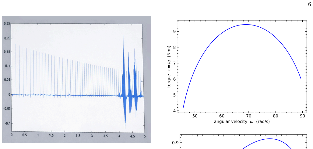
A steel drum with moment of inertia 0.6507 kg m² is mounted on a frame and instrumented with a laser-LDR optical interrupter whose output is sampled at 44.1 kHz by a laptop microphone. Inter-pulse intervals yield angular acceleration, from which torque and power are computed in software. Validation on a 50 cc scooter confirms the apparatus recovers the expected flat-power, falling-torque behavior of its CVT in the low-to-moderate RPM range.
What carries the argument
The optical interrupter timing combined with the known drum inertia to compute torque via τ = I α and power via P = τ ω from pulse intervals.
If this is right
- The apparatus integrates lathe work, welding, analogue electronics and numerical processing into one student project.
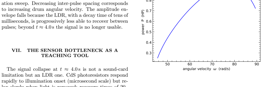
- The LDR recovery time imposes a bandwidth limit that teaches sensor physics as part of the experiment.
- Supplementary code allows replication of the signal-processing steps in MATLAB or Python.
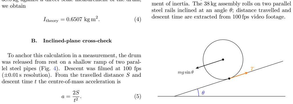
- An independent inclined-plane rolling test cross-validates the drum's moment of inertia.
Where Pith is reading between the lines
- The same timing method could be applied to other rotating systems in educational labs to measure similar dynamics.
- Extending the RPM range would require addressing the sensor bandwidth limit explicitly.
- Such projects might increase engagement in physics among students who prefer practical work.
Load-bearing premise
The millisecond-scale recovery time of the light-dependent resistor and the 44.1 kHz laptop sampling rate supply pulse timing accurate enough to reconstruct undistorted torque and power curves across the tested RPM range.
What would settle it
A wide-open-throttle run on the same 50 cc scooter that fails to produce a flat power curve and declining torque in the low-to-moderate RPM range would indicate the apparatus does not reliably capture the expected dynamics.
Figures


read the original abstract
We report the design, construction, and classroom use of a low-cost inertia dynamometer, built as a year-long project-based learning (PBL) activity with adult students at a Greek Evening Vocational High School (EPAL). The apparatus consists of a machined steel drum of calculated moment of inertia $I = 0.6507~\mathrm{kg\,m^2}$, mounted on a student-welded frame and instrumented with a green-laser / light-dependent resistor (LDR) optical interrupter. The analogue output is sampled at 44.1\,kHz by the microphone input of a laptop computer, which is used as an opportunistic analogue-to-digital converter; torque and power curves are then reconstructed in software from the inter-pulse intervals via $\tau = I\alpha$ and $P = \tau\omega$. The drum's moment of inertia is cross-checked by an inclined-plane rolling experiment. A wide-open-throttle test with a 50\,cc scooter reproduces the expected flat-power / falling-torque signature of a continuously variable transmission in the low-to-moderate RPM range; the LDR's millisecond-scale recovery time imposes an upper bandwidth limit that provides an unplanned but pedagogically rich lesson in sensor physics. The project integrated industrial-lathe fabrication, arc welding, analogue electronics, and numerical differentiation into a single coherent workflow. We describe the apparatus, the physics, the signal-processing pipeline (for which MATLAB and Python/Octave code are provided as supplementary material), and reflect on the pedagogical outcomes for a student population traditionally disengaged from abstract physics.
Editorial analysis
A structured set of objections, weighed in public.
Referee Report
Summary. The manuscript reports the construction of a low-budget inertia dynamometer as a PBL project with vocational students. The apparatus uses a steel drum of I = 0.6507 kg m² on a welded frame, instrumented with a laser-LDR optical interrupter whose analogue signal is sampled at 44.1 kHz via a laptop's microphone input. Torque and power are computed from inter-pulse intervals using Newtonian relations τ = I α and P = τ ω. The moment of inertia is independently verified by an inclined-plane rolling experiment. A wide-open-throttle test on a 50 cc scooter reproduces the characteristic flat power and decreasing torque curve of a CVT at low-to-moderate RPMs. Supplementary code in MATLAB and Python/Octave is provided, and the project integrates fabrication, electronics, and data analysis skills.
Significance. If the timing-based measurements are shown to be sufficiently accurate, the work demonstrates a replicable, inexpensive tool for hands-on teaching of rotational dynamics and the practical effects of sensor bandwidth limits. The cross-validation of I, open-source code, and integration into vocational education are notable strengths that could inspire similar projects elsewhere.
major comments (2)
- [Signal-processing pipeline] The derivation of ω and α from inter-pulse intervals (via the 44.1 kHz sampled LDR signal) is central to the torque and power curves. The manuscript acknowledges the LDR's millisecond-scale recovery time but provides no raw waveform examples, edge-detection thresholds, or propagated uncertainty estimates (in the text or supplementary code) to demonstrate that timing errors do not distort the observed flat-power/falling-torque signature.
- [Scooter test and results] The reproduction of the expected CVT behavior is presented qualitatively without quantitative metrics such as R² values for the power curve, error bars on the data points, or direct comparison to manufacturer specifications. This limits the strength of the claim that the apparatus reliably captures the dynamics.
minor comments (2)
- [Abstract] The value I = 0.6507 kg m² is given with four decimal places; the text should indicate the precision expected from the geometric calculation and any machining tolerances.
- [Pedagogical reflection] More concrete details on how the project affected student understanding of rotational dynamics would enhance the educational claims.
Simulated Author's Rebuttal
We thank the referee for the constructive feedback on our manuscript. The comments highlight opportunities to improve the clarity and rigor of the signal-processing description and the presentation of experimental results. We address each major comment below and commit to revisions that strengthen the paper without altering its core claims.
read point-by-point responses
-
Referee: [Signal-processing pipeline] The derivation of ω and α from inter-pulse intervals (via the 44.1 kHz sampled LDR signal) is central to the torque and power curves. The manuscript acknowledges the LDR's millisecond-scale recovery time but provides no raw waveform examples, edge-detection thresholds, or propagated uncertainty estimates (in the text or supplementary code) to demonstrate that timing errors do not distort the observed flat-power/falling-torque signature.
Authors: We agree that explicit documentation of the signal-processing steps is needed to allow readers to evaluate the reliability of the derived curves. In the revised manuscript we will add a figure displaying a representative segment of the raw LDR waveform with detected rising/falling edges marked, describe the fixed voltage threshold used for edge detection, and revise the supplementary MATLAB and Python/Octave code to propagate timing uncertainties (incorporating both the 44.1 kHz sampling interval and the LDR recovery time) into the computed ω, α, τ and P values. These additions will quantify the maximum possible distortion in the reported flat-power/falling-torque signature. revision: yes
-
Referee: [Scooter test and results] The reproduction of the expected CVT behavior is presented qualitatively without quantitative metrics such as R² values for the power curve, error bars on the data points, or direct comparison to manufacturer specifications. This limits the strength of the claim that the apparatus reliably captures the dynamics.
Authors: We acknowledge that the scooter-test results would be more persuasive with quantitative support. We will add error bars to all torque and power data points derived from the propagated timing uncertainties, report R² values for the power curve in the relevant RPM range, and include a brief comparison to published CVT torque/power trends for small-displacement engines. Direct manufacturer specifications for this exact 50 cc model at the tested low-to-moderate RPMs are not available in the public domain, but the revised text will note this limitation while still demonstrating consistency with the expected qualitative behavior. revision: partial
Circularity Check
No circularity in the derivation chain
full rationale
The paper presents an experimental construction and measurement workflow. The moment of inertia is obtained from direct geometric calculation of the machined drum and cross-validated by a separate inclined-plane rolling experiment; torque and power follow from the standard Newtonian relations τ = Iα and P = τω applied to measured inter-pulse intervals. The observed flat-power/falling-torque signature is reported as an experimental outcome that matches prior knowledge of CVT behavior, not a quantity derived from or fitted to the apparatus data itself. No self-citations, ansatzes, uniqueness theorems, or renamings of known results appear in the load-bearing steps. The chain is self-contained against external benchmarks and independent measurements.
Axiom & Free-Parameter Ledger
axioms (2)
- standard math Torque equals moment of inertia times angular acceleration (tau = I alpha)
- standard math Power equals torque times angular velocity (P = tau omega)
Reference graph
Works this paper leans on
-
[1]
K. K. Mashood and V. A. Singh, Development and eval- uation of a concept inventory in rotational kinematics, European Journal of Physics36, 015015 (2014)
2014
-
[2]
L. G. Rimoldini and C. Singh, Student understanding of rotational and rolling motion concepts, Physical Review Special Topics – Physics Education Research1, 010102 (2005)
2005
-
[3]
H. G. Close and P. R. L. Heron, Student understanding of the angular momentum of classical particles, American Journal of Physics79, 1068 (2011)
2011
-
[4]
A. E. Rivet and J. S. Krajcik, Contextualizing instruc- tion: Leveraging students’ prior knowledge and experi- ences to foster understanding of middle school science, Journal of Research in Science Teaching45, 79 (2008)
2008
-
[5]
Chiang and H.-M
C.-L. Chiang and H.-M. Lee, The effect of project-based learning on learning motivation and problem-solving abil- ity of vocational high school students, International Jour- nal of Information and Education Technology6, 709 (2016)
2016
-
[6]
Urrutia-Heinzet al., Problem-based learning as a strategy for teaching physics in technical–professional higher education: A case study in Chile, Education Sci- ences15, 941 (2024)
M. Urrutia-Heinzet al., Problem-based learning as a strategy for teaching physics in technical–professional higher education: A case study in Chile, Education Sci- ences15, 941 (2024)
2024
-
[7]
Bouquet, J
F. Bouquet, J. Bobroff, M. Fuchs-Gallezot, and L. Mau- rines, Project-based physics labs using low-cost open- source hardware, American Journal of Physics85, 216 (2017)
2017
-
[8]
J. M. Pearce, Impacts of open source hardware in science and engineering, The Bridge47, 24 (2017)
2017
-
[9]
D’Ausilio, Arduino: A low-cost multipurpose lab equipment, Behavior Research Methods44, 305 (2012)
A. D’Ausilio, Arduino: A low-cost multipurpose lab equipment, Behavior Research Methods44, 305 (2012)
2012
-
[10]
A. J. Martyr and M. A. Plint,Engine Testing: Theory and Practice, 4th ed. (Butterworth-Heinemann, Oxford, 2012). 8
2012
-
[11]
C. E. Aguiar and M. M. Pereira, Using the sound card as a timer, The Physics Teacher49, 33 (2011)
2011
-
[12]
Hassan, S
U. Hassan, S. Pervaiz, and M. S. Anwar, Inexpensive data acquisition with a sound card, The Physics Teacher49, 537 (2011)
2011
-
[13]
Lave and E
J. Lave and E. Wenger,Situated Learning: Legitimate Peripheral Participation(Cambridge University Press, Cambridge, 1991)
1991
-
[14]
Bandura, Self-efficacy: Toward a unifying theory of behavioral change, Psychological Review84, 191 (1977)
A. Bandura, Self-efficacy: Toward a unifying theory of behavioral change, Psychological Review84, 191 (1977)
1977
-
[15]
Halliday, R
D. Halliday, R. Resnick, and J. Walker,Fundamentals of Physics, 10th ed. (Wiley, New York, 2013)
2013
-
[16]
Savitzky and M
A. Savitzky and M. J. E. Golay, Smoothing and differ- entiation of data by simplified least squares procedures, Analytical Chemistry36, 1627 (1964)
1964
-
[17]
Kapur, Productive failure, Cognition and Instruction 26, 379 (2008)
M. Kapur, Productive failure, Cognition and Instruction 26, 379 (2008)
2008
discussion (0)
Sign in with ORCID, Apple, or X to comment. Anyone can read and Pith papers without signing in.