Recognition: unknown
Cordierite-based optical resonators with extremely low thermal expansion
Pith reviewed 2026-05-15 00:41 UTC · model grok-4.3
The pith
Cordierite spacers with ULE mirrors keep effective thermal expansion near zero over tens of Kelvin by offsetting spacer growth with mirror bending.
A machine-rendered reading of the paper's core claim, the machinery that carries it, and where it could break.
Core claim
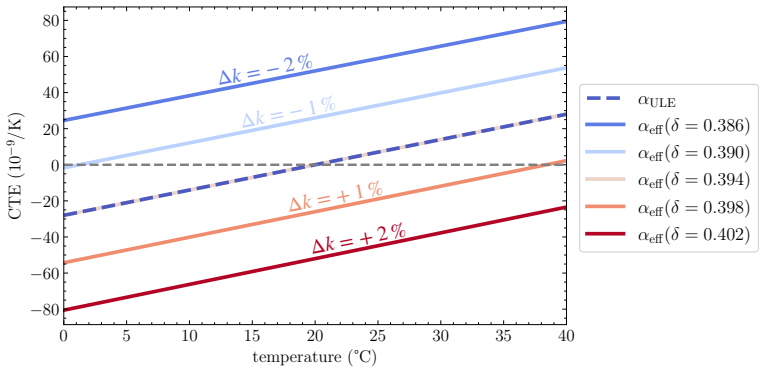
A cordierite spacer combined with ULE mirrors can be configured so that the thermal expansion of the spacer is fully or partially compensated by mirror deflection arising from the CTE mismatch, yielding an effective resonator CTE close to zero over a temperature range of several tens of Kelvin.
What carries the argument
Mirror deflection under CTE mismatch that offsets the spacer's thermal length change, quantified through finite element simulations of the composite structure.
If this is right
- Cordierite resonators with fused silica mirrors require no additional compensation rings because high stiffness suppresses the effect of the CTE mismatch.
- The compensation approach enables compact room-temperature resonators with effective CTE near zero over tens of Kelvin.
- The same mirror-deflection principle extends directly to silicon or other stiff crystalline spacers for terrestrial and space-borne applications.
Where Pith is reading between the lines
- The design could reduce the need for active temperature stabilization in portable optical frequency references.
- Similar compensation might be tested in other high-stiffness, low-expansion ceramics to further widen the usable temperature window.
- The method offers a passive route to thermal stability that could complement existing vibration-isolation techniques.
Load-bearing premise
Finite element simulations accurately capture the mechanical deflection and thermal expansion mismatch without unmodeled effects such as mounting stresses or surface coatings.
What would settle it
A direct interferometric measurement of resonator length versus temperature that shows no broad zero-crossing or that deviates sharply from the simulated compensation curve.
Figures


read the original abstract
Applications for ultra-stable lasers outside controlled laboratory environments require compact and robust optical resonators with reduced sensitivity to temperature fluctuations. The low thermal expansion coefficient (CTE) and the high stiffness make cordierite-based ceramics, such as NEXCERA, attractive for vibration insensitive room-temperature resonators. We revisit the effective CTE of resonators with spacers and mirrors made of different materials and use finite element simulations to analyze the impact of a CTE mismatch in a cordierite-based resonator with mirrors made of ultra-low expansion (ULE) glass or fused silica (FS). This enabled us to determine the CTE of a cordierite spacer from the measured effective CTE of a resonator. We confirm a six-fold larger CTE slope of cordierite around the zero-crossing temperature than in ULE glass. The steep CTE slope, in combination with the large stiffness, makes cordierite-based resonators far less sensitive to CTE mismatch with FS mirrors, thereby eliminating the need for additional compensation rings. We further consider the so far neglected case, where the CTE of the spacer is larger than that of the mirror, and propose resonator designs in which the thermal length change of the spacer is fully or partially compensated by the deflection of the mirrors. This results in a cordierite-based resonator with ULE mirrors whose effective CTE can be close to zero over a temperature range of several tens of Kelvin. We are extending our concept to resonators based on crystalline materials with high stiffness and low isothermal length change, such as silicon, enabling compact and robust room-temperature resonators for terrestrial and space-born applications.
Editorial analysis
A structured set of objections, weighed in public.
Referee Report
Summary. The paper analyzes cordierite-based optical resonators for ultra-stable lasers, using finite-element simulations to examine CTE mismatch between a cordierite spacer and ULE or fused-silica mirrors. It extracts the cordierite CTE from measured resonator data, reports a six-fold steeper CTE slope near the zero-crossing than ULE, and proposes new geometries in which mirror deflection compensates the spacer's larger thermal expansion, yielding an effective CTE near zero over tens of kelvin without compensation rings.
Significance. If the FEM predictions hold, the work offers a practical route to compact, high-stiffness resonators with broad-temperature stability that could benefit terrestrial and space-borne ultra-stable laser systems by removing the need for auxiliary compensation elements.
major comments (3)
- [section proposing resonator designs] The headline claim that a cordierite-ULE resonator can achieve effective CTE near zero over several tens of kelvin rests entirely on FEM predictions of mirror deflection compensating spacer expansion; the manuscript reports no experimental realization or validation of any compensated geometry, only extraction from a single uncompensated resonator.
- [CTE extraction and slope comparison] The extraction of cordierite CTE from measured effective CTE via FEM (used to establish the six-fold larger slope) provides no error bars, raw frequency or temperature data, or independent cross-check against dilatometry or other methods, leaving the quantitative slope comparison only moderately supported.
- [finite element simulations of CTE mismatch] The FEM analysis of mismatch-induced bending assumes ideal boundary conditions and omits sensitivity to mounting stresses, coatings, or surface effects; no quantitative assessment of how these would shift the compensation point is given, directly affecting the central claim of robust near-zero effective CTE.
minor comments (2)
- [figures] Figure captions and axis labels for the simulated deflection and effective-CTE curves should explicitly state the assumed boundary conditions and material parameters used.
- [abstract and results] The abstract states the effective CTE 'can be close to zero' but the main text should quantify the temperature range and residual CTE value with the specific geometry parameters chosen.
Simulated Author's Rebuttal
We thank the referee for the careful and constructive review of our manuscript. We address each major comment point by point below, providing clarifications on the scope of our work and indicating where revisions or additional analysis will strengthen the presentation.
read point-by-point responses
-
Referee: The headline claim that a cordierite-ULE resonator can achieve effective CTE near zero over several tens of kelvin rests entirely on FEM predictions of mirror deflection compensating spacer expansion; the manuscript reports no experimental realization or validation of any compensated geometry, only extraction from a single uncompensated resonator.
Authors: We agree that the compensated resonator geometries are proposed on the basis of finite-element modeling and have not been fabricated or measured in this study. The manuscript extracts the cordierite CTE from an existing uncompensated device and then uses FEM to explore new mirror-deflection compensation schemes. This is presented as a design proposal for future experimental realization rather than a claim of demonstrated performance. We will revise the text to make this distinction clearer and to emphasize that the central result is the identification of viable geometries via simulation. revision: no
-
Referee: The extraction of cordierite CTE from measured effective CTE via FEM (used to establish the six-fold larger slope) provides no error bars, raw frequency or temperature data, or independent cross-check against dilatometry or other methods, leaving the quantitative slope comparison only moderately supported.
Authors: The cordierite CTE was obtained by fitting the measured effective CTE of our resonator with FEM. We accept that the absence of error bars and raw data reduces the strength of the quantitative comparison. In the revised manuscript we will include error estimates on the extracted CTE curve and add the raw frequency-versus-temperature data to the supplementary material. An independent dilatometry cross-check is not available from our current dataset. revision: partial
-
Referee: The FEM analysis of mismatch-induced bending assumes ideal boundary conditions and omits sensitivity to mounting stresses, coatings, or surface effects; no quantitative assessment of how these would shift the compensation point is given, directly affecting the central claim of robust near-zero effective CTE.
Authors: The simulations employ idealized boundary conditions. We will add a quantitative sensitivity study in the revised manuscript that examines the influence of mounting stresses, coating thickness variations, and surface roughness on the location of the compensation point and on the resulting effective CTE. This will provide bounds on how far the near-zero region may shift under realistic conditions. revision: yes
Circularity Check
No significant circularity; compensation claim follows from forward FEM modeling of extracted CTE
full rationale
The paper measures resonator effective CTE, then uses FEM to back-extract cordierite spacer CTE. It subsequently runs the same model forward on new geometries to predict mirror-deflection compensation when spacer CTE exceeds mirror CTE. This is a standard parameter-extraction-plus-prediction workflow, not a reduction of the output to the input by definition or by self-citation. No load-bearing step equates the claimed near-zero effective CTE over tens of K to a fitted quantity by construction; the result remains contingent on the independent validity of the FEM boundary conditions and material models.
Axiom & Free-Parameter Ledger
free parameters (1)
- cordierite CTE =
extracted from resonator data
axioms (1)
- domain assumption Finite-element method correctly predicts coupled thermal-mechanical deformation of the mirror-spacer assembly.
Reference graph
Works this paper leans on
-
[1]
Optical atomic clocks,
A. D. Ludlow, M. M. Boyd, J. Ye,et al., “Optical atomic clocks,” Rev. Mod. Phys.87, 637–701 (2015)
2015
-
[2]
1.5𝜇m Lasers with Sub-10 mHz Linewidth,
D. G. Mateiet al., “1.5𝜇m Lasers with Sub-10 mHz Linewidth,” Phys. Rev. Lett.118, 263202 (2017)
2017
-
[3]
Ultrastable Silicon Cavity in a Continuously Operating Closed-Cycle Cryostat at 4 K,
W. Zhanget al., “Ultrastable Silicon Cavity in a Continuously Operating Closed-Cycle Cryostat at 4 K,” Phys. Rev. Lett.119, 243601 (2017)
2017
-
[4]
Demonstration of 4.8×10⁻¹⁷ stability at 1s for two independent optical clocks,
E. Oelkeret al., “Demonstration of 4.8×10⁻¹⁷ stability at 1s for two independent optical clocks,” Nat. Photon.13, 714–719 (2019)
2019
-
[5]
The Einstein Telescope: a third-generation gravitational wave observatory,
M. Punturoet al., “The Einstein Telescope: a third-generation gravitational wave observatory,” Class. Quantum Grav. 27, 194002 (2010)
2010
-
[6]
Interferometer design of the KAGRA gravitational wave detector,
Y. Aso, Y. Michimura, K. Somiya,et al., “Interferometer design of the KAGRA gravitational wave detector,” Phys. Rev. D88, 043007 (2013)
2013
-
[7]
Advanced Virgo: a second-generation interferometric gravitational wave detector,
F. Acerneseet al., “Advanced Virgo: a second-generation interferometric gravitational wave detector,” Class. Quantum Grav.32, 024001 (2014)
2014
-
[8]
Advanced LIGO,
The LIGO Scientific Collaborationet al., “Advanced LIGO,” Class. Quantum Grav.32, 074001 (2015)
2015
-
[9]
The Science of the Einstein Telescope
A. Abacet al., “The Science of the Einstein Telescope,” arXiv2503.12263(2025)
work page internal anchor Pith review Pith/arXiv arXiv 2025
-
[10]
Relativity in the Global Positioning System,
N. Ashby, “Relativity in the Global Positioning System,” Living Rev. Relativ.6, 1 (2003)
2003
-
[11]
Search for domain wall dark matter with atomic clocks on board global positioning system satellites,
B. M. Roberts, G. Blewitt, C. Dailey,et al., “Search for domain wall dark matter with atomic clocks on board global positioning system satellites,” Nat. Commun.8, 1995 (2017)
1995
-
[12]
Gravitational Redshift Test Using Eccentric Galileo Satellites,
P. Delvaet al., “Gravitational Redshift Test Using Eccentric Galileo Satellites,” Phys. Rev. Lett.121, 231101 (2018)
2018
-
[13]
Demonstration of a Timescale Based on a Stable Optical Carrier,
W. R. Milneret al., “Demonstration of a Timescale Based on a Stable Optical Carrier,” Phys. Rev. Lett.123, 173201 (2019)
2019
-
[14]
Precision Metrology Meets Cosmology: Improved Constraints on Ultralight Dark Matter from Atom-Cavity Frequency Comparisons,
C. J. Kennedy, E. Oelker, J. M. Robinson,et al., “Precision Metrology Meets Cosmology: Improved Constraints on Ultralight Dark Matter from Atom-Cavity Frequency Comparisons,” Phys. Rev. Lett.125, 201302 (2020)
2020
-
[15]
Quantification of broadband chromatic drifts in Fabry-Pérot resonators for exoplanet science,
M. K. Kreider, C. Fredrick, S. A. Diddams,et al., “Quantification of broadband chromatic drifts in Fabry-Pérot resonators for exoplanet science,” Nat. Astron.9, 589–597 (2025)
2025
-
[16]
Stretched exponential relaxation in molecular and electronic glasses,
J. C. Phillips, “Stretched exponential relaxation in molecular and electronic glasses,” Rep. Prog. Phys59, 1133 (1996)
1996
-
[17]
A narrow linewidth and frequency-stable probe laser source for the88Sr+ single ion optical frequency standard,
P. Dubé, A. A. Madej, J. E. Bernard,et al., “A narrow linewidth and frequency-stable probe laser source for the88Sr+ single ion optical frequency standard,” Appl. Phys. B95, 43–54 (2009)
2009
-
[18]
Guidelines for designs for ultrastable laser with10−17 fractional frequency instability,
J. Barbaratet al., “Guidelines for designs for ultrastable laser with10−17 fractional frequency instability,” arXiv 2504.06213(2025)
-
[19]
Stable CW laser based on low thermal expansion ceramic cavity with 4.9 mHz/s frequency drift,
I. Ito, A. Silva, T. Nakamura, and Y. Kobayashi, “Stable CW laser based on low thermal expansion ceramic cavity with 4.9 mHz/s frequency drift,” Opt. Express25, 26020–26028 (2017)
2017
-
[20]
NEXCERA: Ultra low thermal expansion ceramics,
T. Nose, M. Nakabayashi, N. Kosugi,et al., “NEXCERA: Ultra low thermal expansion ceramics,” Nippon. Steel Tech. Rep.84(2001)
2001
-
[21]
Corning ULE 7972 Low Expansion Glass,
Corning Advanced Optics, “Corning ULE 7972 Low Expansion Glass,” (2016)
2016
-
[22]
MechanicallossandstabilityanalysisofNEXCERAinultra-stableoptical cavities,
N.Wagner,N.Narożnik,M.Bober,et al.,“MechanicallossandstabilityanalysisofNEXCERAinultra-stableoptical cavities,” J. Opt. Soc. Am. B42, 2488 (2025)
2025
-
[23]
Mechanical quality factor and thermal noise analysis of NEXCERA for optical cavities,
N. Wagner, M. Narożnik, M. Bober,et al., “Mechanical quality factor and thermal noise analysis of NEXCERA for optical cavities,” inOptical Sensing and Precision Metrology,vol. 13380 (SPIE, 2025), p. 133800N
2025
-
[24]
Microwave photonic radars,
S. Pan and Y. Zhang, “Microwave photonic radars,” J. Light. Technol.38, 5450–5484 (2020)
2020
-
[25]
Using global existing fiber networks for environmental sensing,
E. Ip, F. Ravet, H. Martins,et al., “Using global existing fiber networks for environmental sensing,” Proc. IEEE110, 1853–1888 (2022)
2022
-
[26]
Space clocks and fundamental tests: The ACES experiment,
L. Cacciapuoti and C. Salomon, “Space clocks and fundamental tests: The ACES experiment,” Eur. Phys. J. Spec. Top.172, 57–68 (2009)
2009
-
[27]
High finesse buckled microcavities,
S. W. Ding, B. Grinkemeyer, G. E. Mandopoulou,et al., “High finesse buckled microcavities,” Optica13, 313–318 (2026)
2026
-
[28]
High quality factor measured in fused silica,
S. D. Penn, G. M. Harry, A. M. Gretarsson,et al., “High quality factor measured in fused silica,” Rev. Sci. Instrum. 72, 3670–3673 (2001)
2001
-
[29]
Tuning the thermal expansion properties of optical reference cavities with fused silica mirrors,
T. Legero, T. Kessler, and U. Sterr, “Tuning the thermal expansion properties of optical reference cavities with fused silica mirrors,” J. Opt. Soc. Am. B27, 914 (2010)
2010
-
[30]
Temperature compensation for cryogenic cavity stabilized lasers,
M. Notcutt, C. T. Taylor, A. G. Mann, and D. G. Blair, “Temperature compensation for cryogenic cavity stabilized lasers,” J. Phys. D: Appl. Phys.28, 1807–1810 (1995)
1995
-
[31]
Temperature-compensated cryogenic Fabry–Perot cavity,
E. K. Wong, M. Notcutt, C. T. Taylor,et al., “Temperature-compensated cryogenic Fabry–Perot cavity,” Appl. Opt. 36, 8563–8566 (1997)
1997
-
[32]
COMSOL Multiphysics® v. 6.0. www.comsol.com. COMSOL AB, Stockholm, Sweden
-
[33]
Corning® HPFS® 7979, 7980, 8655 Fused Silica,
Corning Advanced Optics, “Corning® HPFS® 7979, 7980, 8655 Fused Silica,” (2023)
2023
-
[34]
A Fabry–Pérot Etalon with an Ultralow Expansion Ceramic Spacer,
K. Hosaka, H. Inaba, D. Akamatsu,et al., “A Fabry–Pérot Etalon with an Ultralow Expansion Ceramic Spacer,” Jpn. J. Appl. Phys.52, 032402 (2013)
2013
-
[35]
Characterization of the long-term dimensional stability of a NEXCERA block using the optical resonator technique,
C. J. Kwong, M. G. Hansen, J. Sugawara, and S. Schiller, “Characterization of the long-term dimensional stability of a NEXCERA block using the optical resonator technique,” Meas. Sci. Technol.29, 075011 (2018)
2018
-
[36]
Thermal expansion uniformity of Heraeus-Amersil TO8E fused silica,
S. F. Jacobs and D. Shough, “Thermal expansion uniformity of Heraeus-Amersil TO8E fused silica,” Appl. Opt.20, 3461 (1981)
1981
-
[37]
Thermal-noiselimitinthefrequencystabilizationoflaserswithrigidcavities,
K.Numata, A.Kemery, andJ.Camp, “Thermal-noiselimitinthefrequencystabilizationoflaserswithrigidcavities,” Phys. Rev. Lett.93, 250602 (2004)
2004
-
[38]
ThermalnoiseandmechanicallossofSiO 2/Ta2O5 opticalcoatingsatcryogenictemperatures,
J.M.Robinsonet al.,“ThermalnoiseandmechanicallossofSiO 2/Ta2O5 opticalcoatingsatcryogenictemperatures,” Opt. Lett.46, 592–595 (2021)
2021
-
[39]
Tenfold reduction of brownian noise in high-reflectivity optical coatings,
G. D. Cole, W. Zhang, M. J. Martin,et al., “Tenfold reduction of brownian noise in high-reflectivity optical coatings,” Nat. Photon.7, 644–650 (2013)
2013
-
[40]
Ultrastable vacuum-gap Fabry-Perot cavities operated in air,
Y. Liu, N. Jin, D. Lee,et al., “Ultrastable vacuum-gap Fabry-Perot cavities operated in air,” Optica11, 1205 (2024)
2024
-
[41]
Fiber-coupled 2 mL vacuum-gap Fabry-Perot reference cavity for portable laser stabilization,
C. A. McLemore, N. Jin, M. L. Kelleher,et al., “Fiber-coupled 2 mL vacuum-gap Fabry-Perot reference cavity for portable laser stabilization,” Opt. Lett.49, 4737 (2024)
2024
-
[42]
Frequency Stability of2.5×10 −17 from a Si Cavity with AlGaAs Crystalline Mirrors,
D. Lee, Z. Z. Hu, B. Lewis,et al., “Frequency Stability of2.5×10 −17 from a Si Cavity with AlGaAs Crystalline Mirrors,” Phys. Rev. Lett.136, 033801 (2026)
2026
-
[43]
Thermal noise in optical cavities revisited,
T. Kessler, T. Legero, and U. Sterr, “Thermal noise in optical cavities revisited,” J. Opt. Soc. Am. B29, 178–184 (2012)
2012
-
[44]
Linear thermal expansion measurements on silicon from 6 to 340 K,
K. G. Lyon, G. L. Salinger, C. A. Swenson, and G. K. White, “Linear thermal expansion measurements on silicon from 6 to 340 K,” J. Appl. Phys.48, 865–868 (1977)
1977
discussion (0)
Sign in with ORCID, Apple, or X to comment. Anyone can read and Pith papers without signing in.